

No Idea
-
Posts
1,036 -
Joined
-
Last visited
Content Type
Profiles
Forums
Gallery
Events
Posts posted by No Idea
-
-
-
Glad you’re back building again - the work looks fantastic 👍
- mtaylor and native one
-
 2
2
-
-
Another update from me - its all or nothing with me at the moment I can only apologise 😀
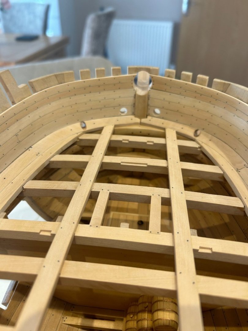
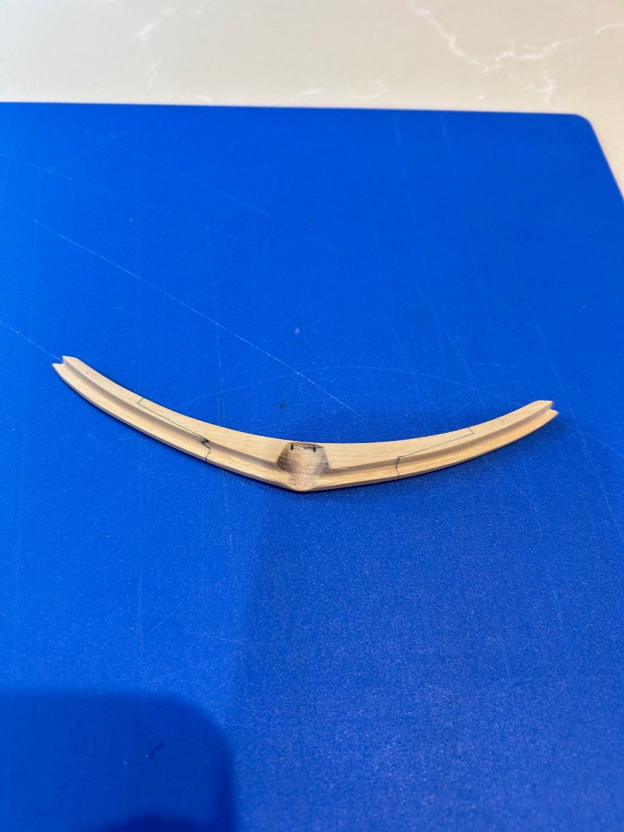
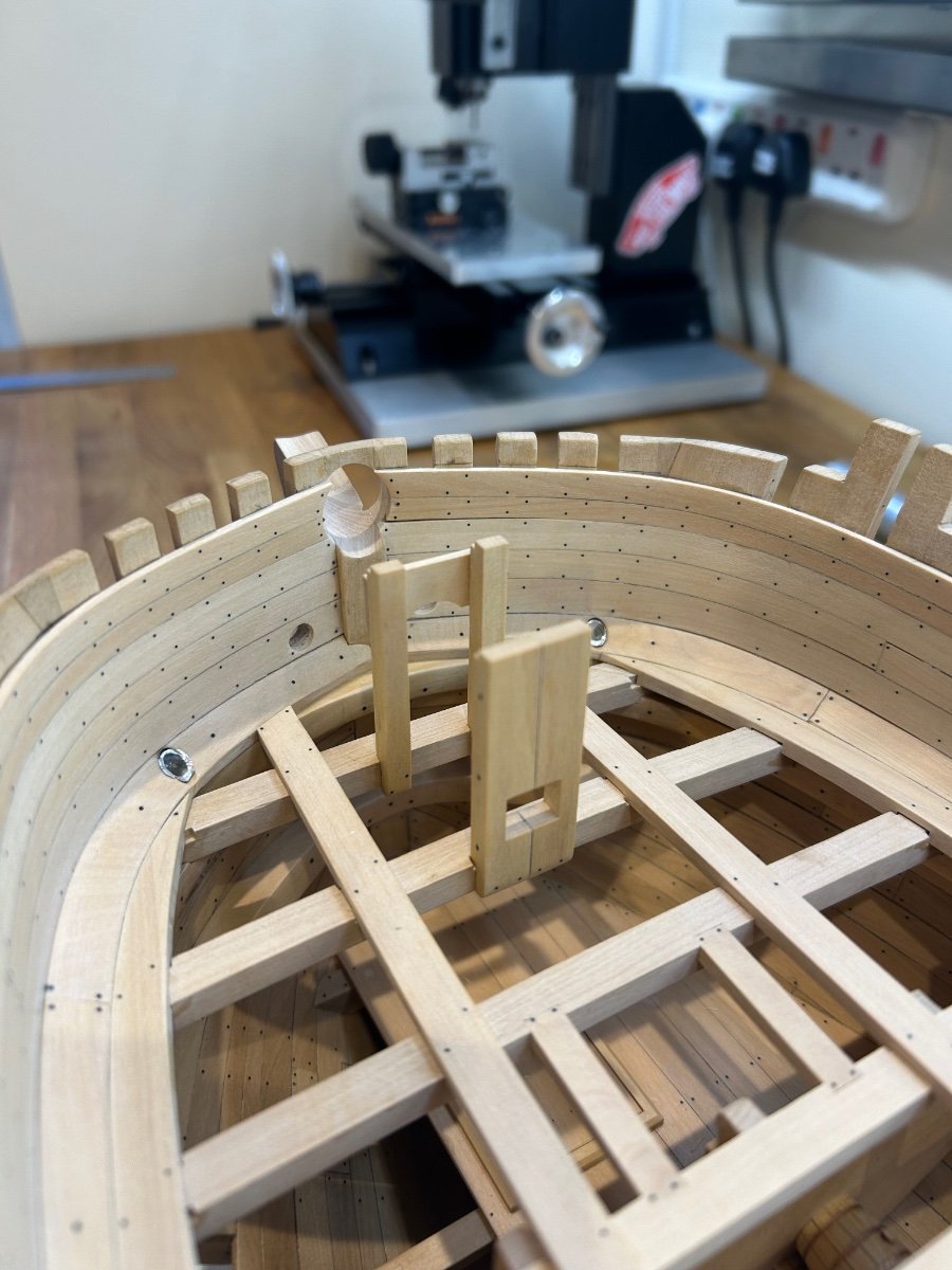
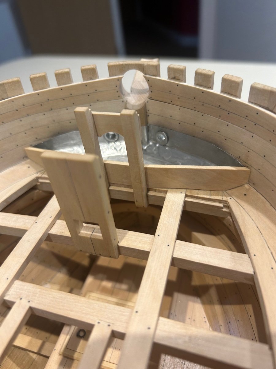
The final 2 breast hooks for the hawse timbers. The upper one is made of 3 pieces which then go on to be attached to the forward deck beam supports.
The second is one piece - so I dimensioned the wood and roughly cut them out as per usual. It's worth noting that the upper breast hook is made from a piece that starts at 11mm thick.
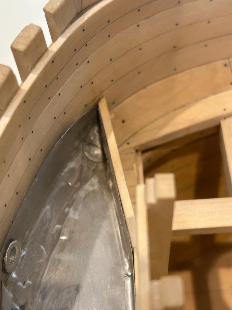
The lower breast hook is very straight forward and is just like all of the others that I have made. The only difference is that you have to cut a channel for the bowsprit which is set at 17 degrees.

Installation is also just as before - take your time and get a good fit onto the hawse timbers. I see this bit as a challenge to get it as tight as possible.
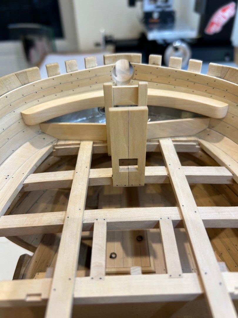
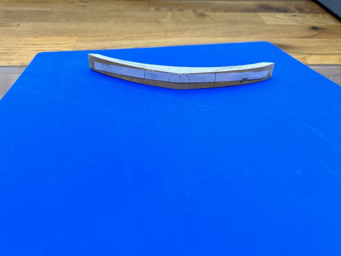
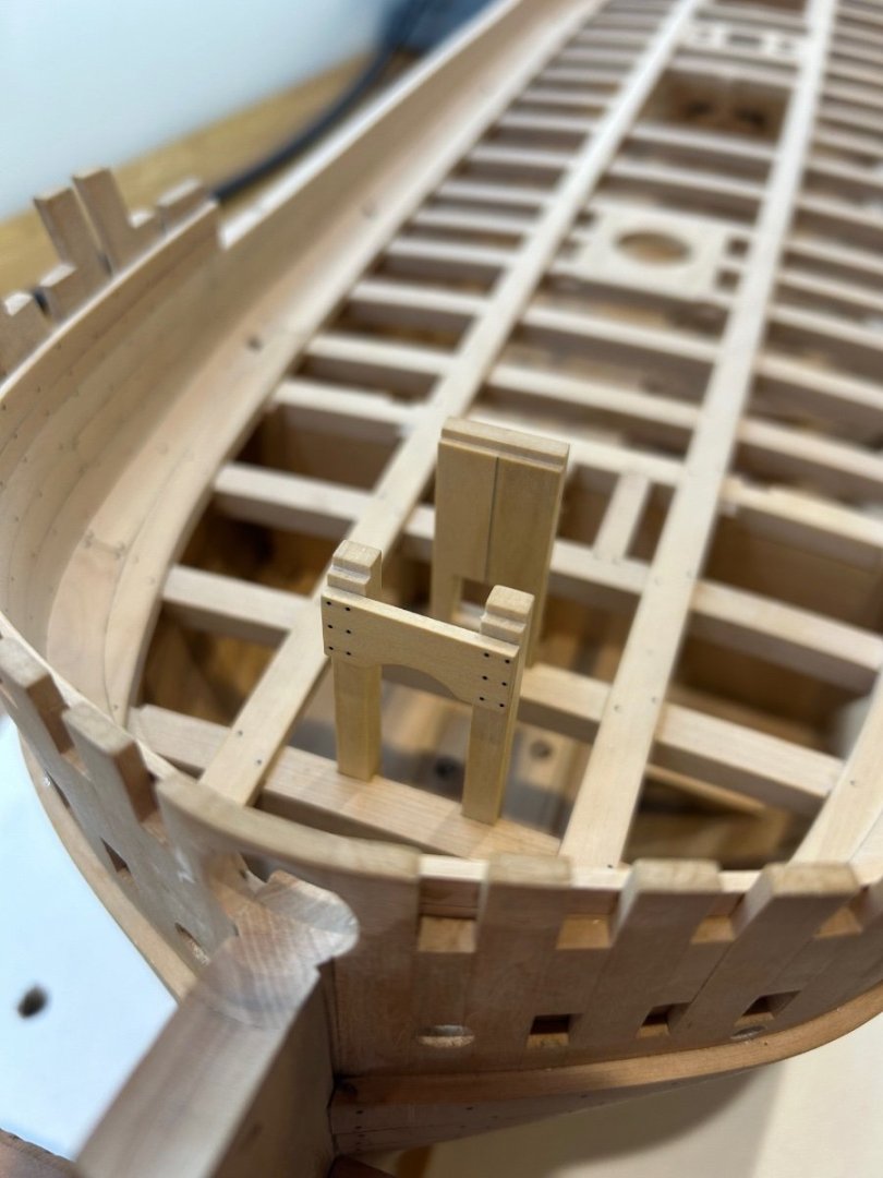
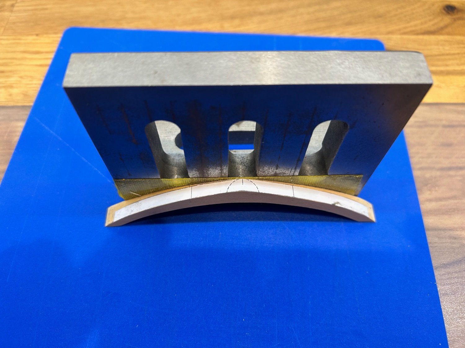
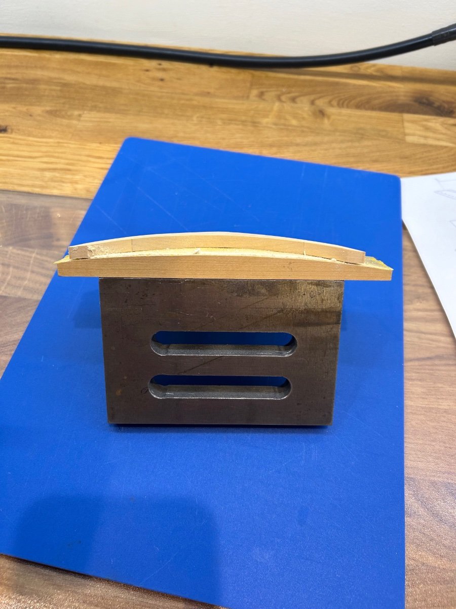
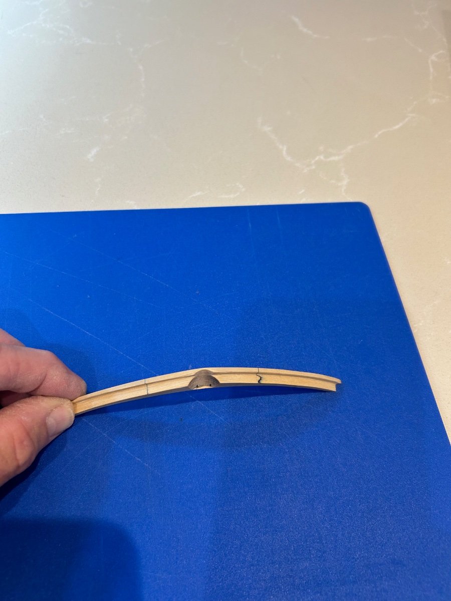
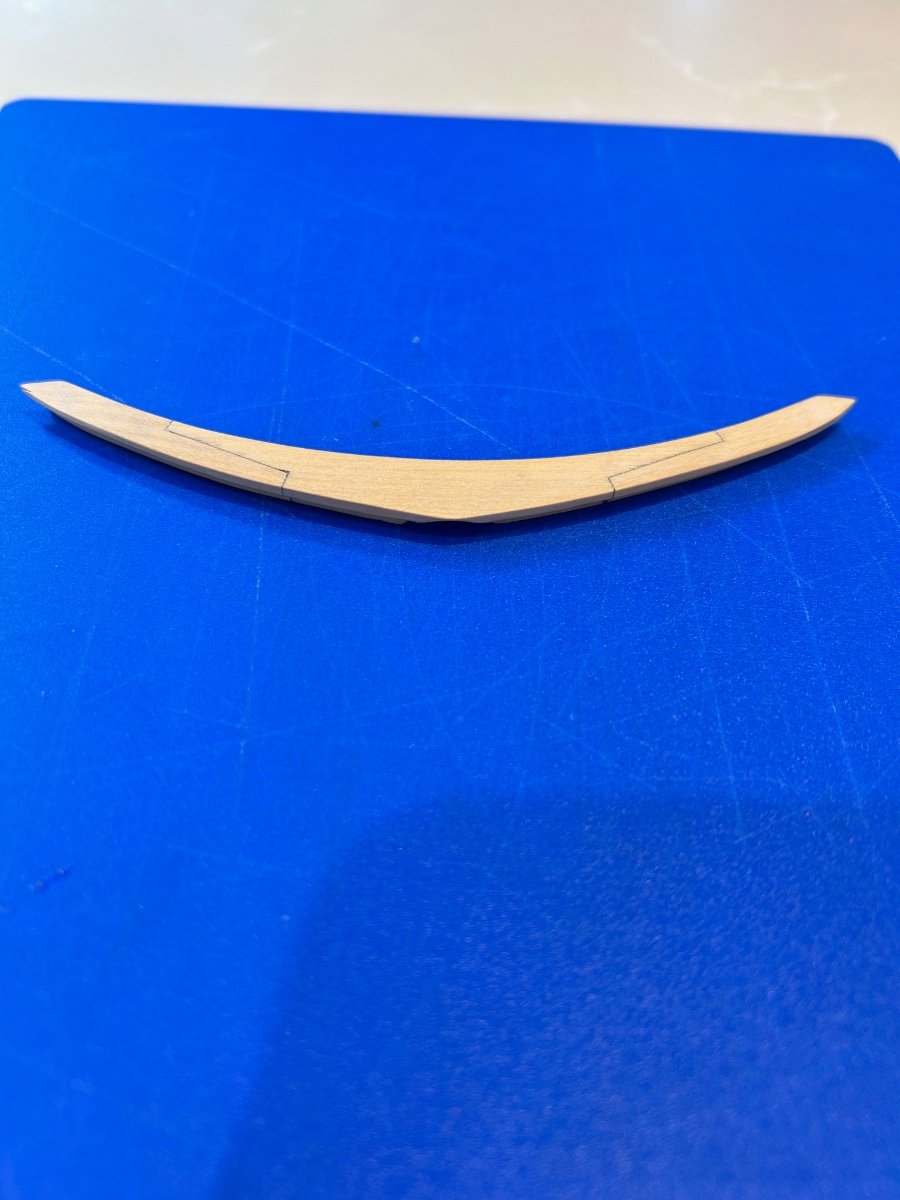
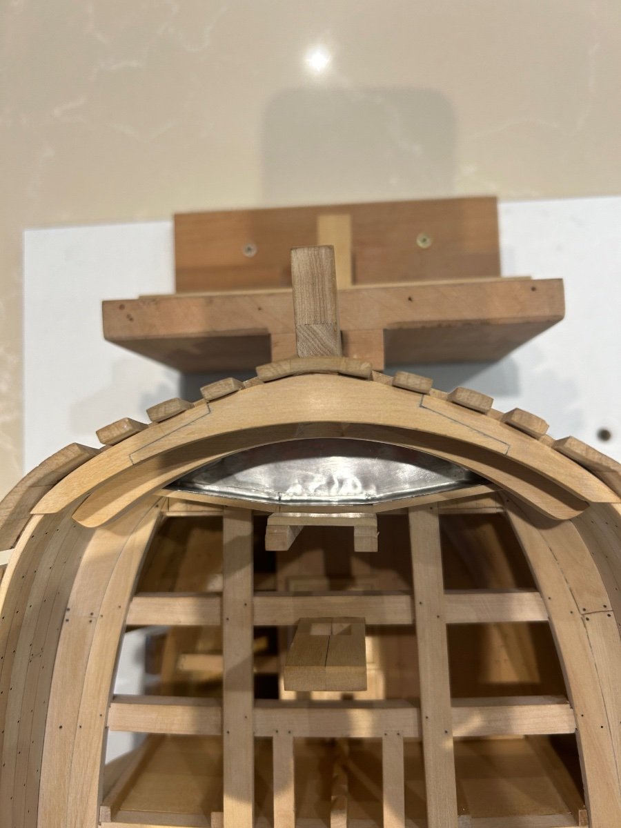
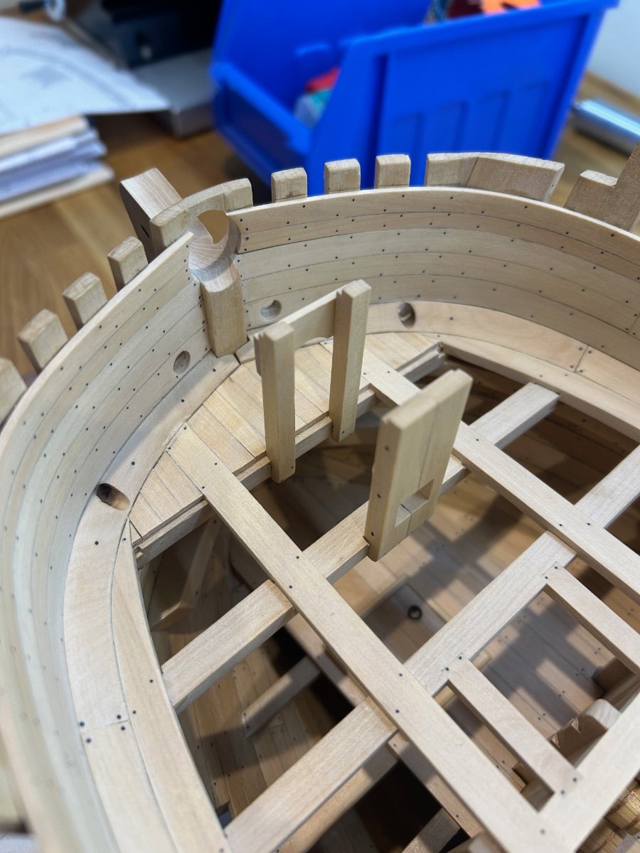
Now the very top breast hook is a very different thing to make. It has a gentle curve to match the clamp and the forward deck as the deck timbers sit directly onto it. It is also parallel in thickness throughout its curve; is recessed onto the clamp and has to align with the bowsprit too. I hope your keeping up 😆
So after a bit of thought this was my solution to making this piece which cost me quite a bit in wood as I didn't have anything else in the house other than Castello.
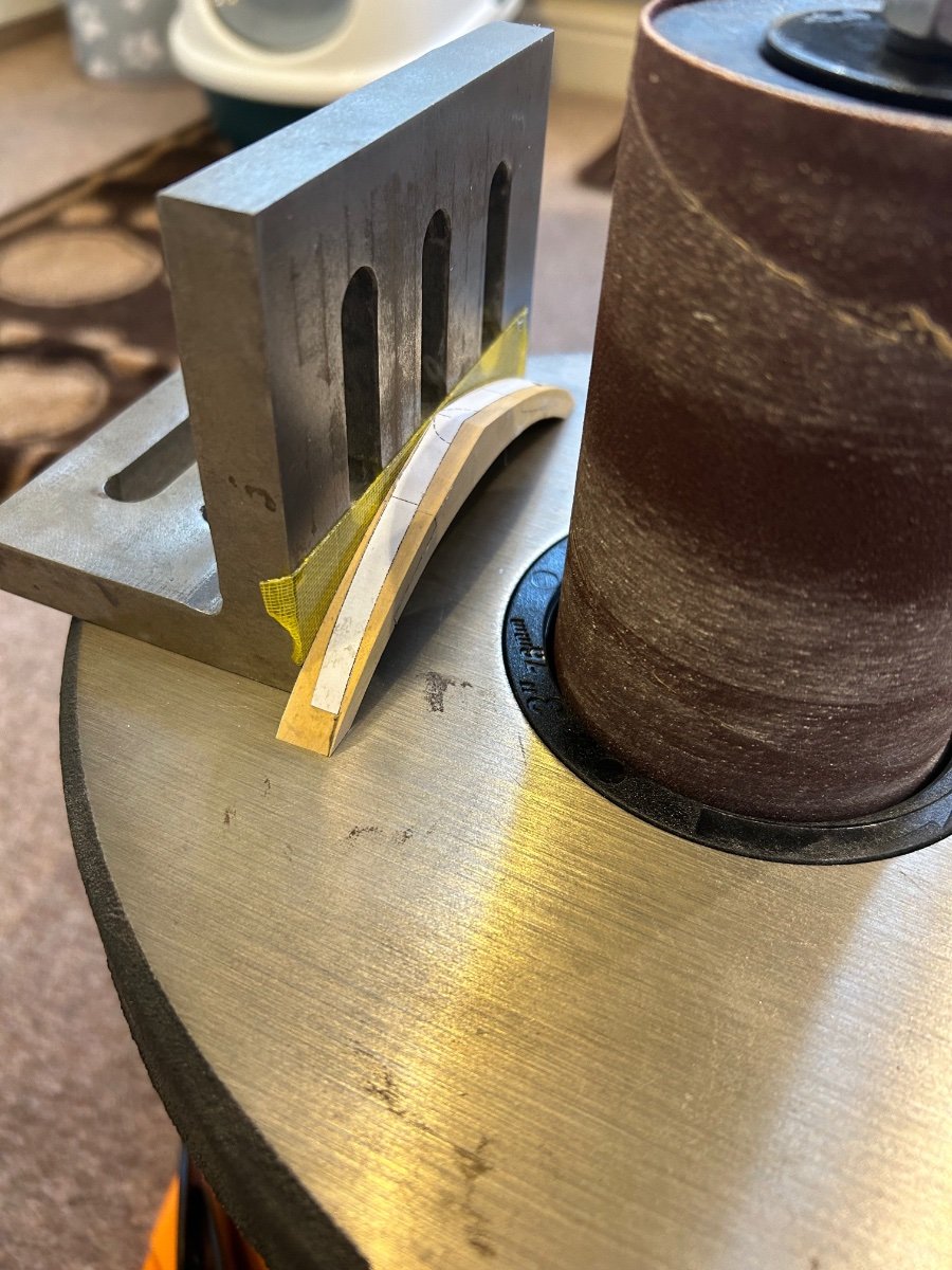
Firstly I shaped the perimeter of it as per the drawings - this is the easy bit. Next to shape the inside curve I attached it to an angle plate to ensure a 90 degree cut.

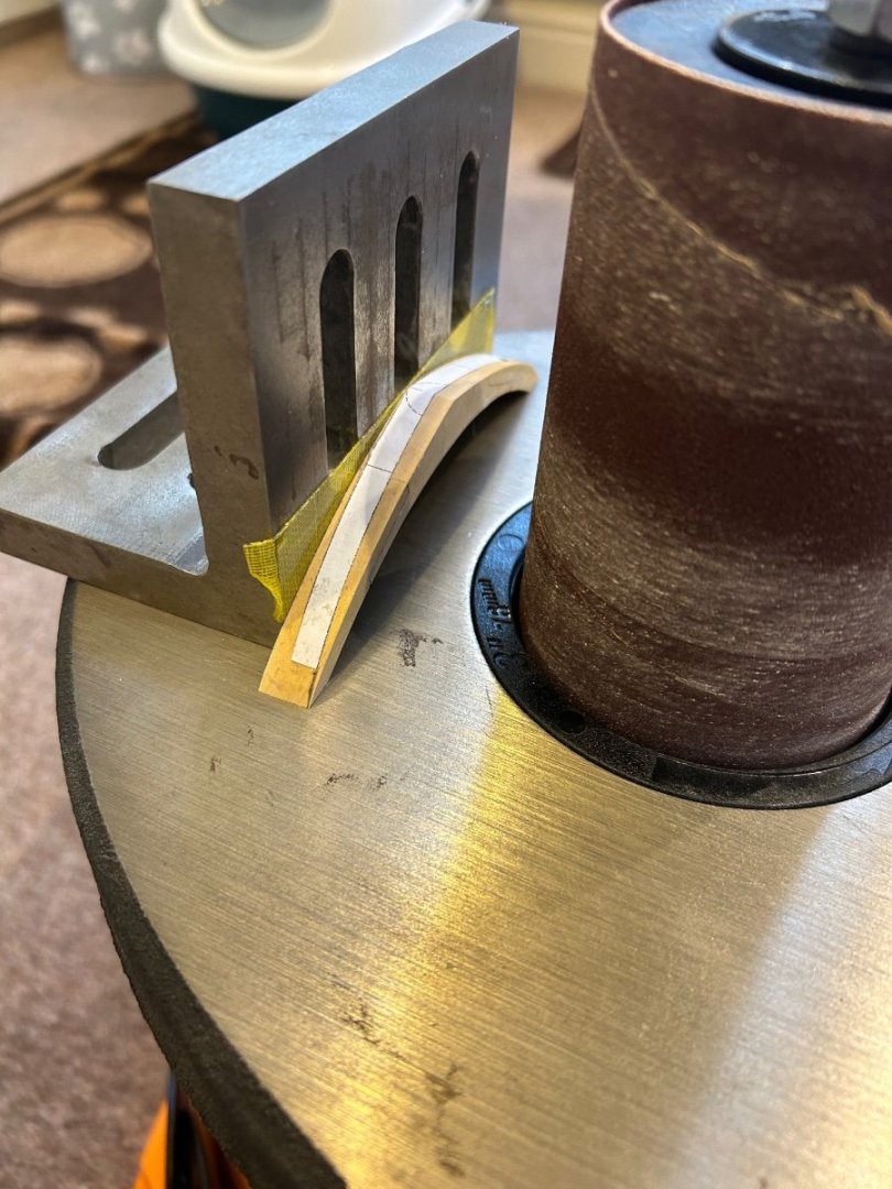
I then made a jig which matched the curve that I had just cut and once again attached it to an angle plate for a 90 degree cut.


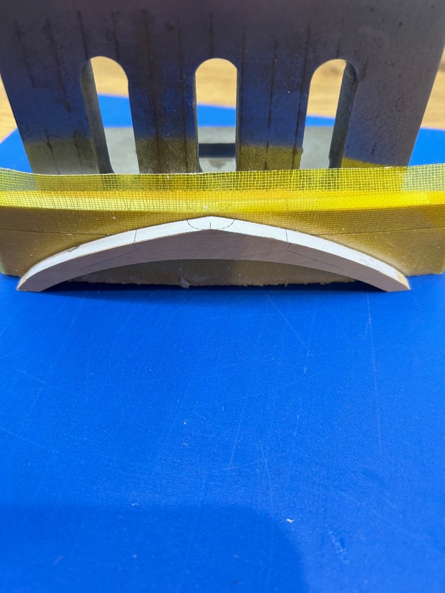
Next was to cut the recess for the clamp and again cut another recess for the bowsprit


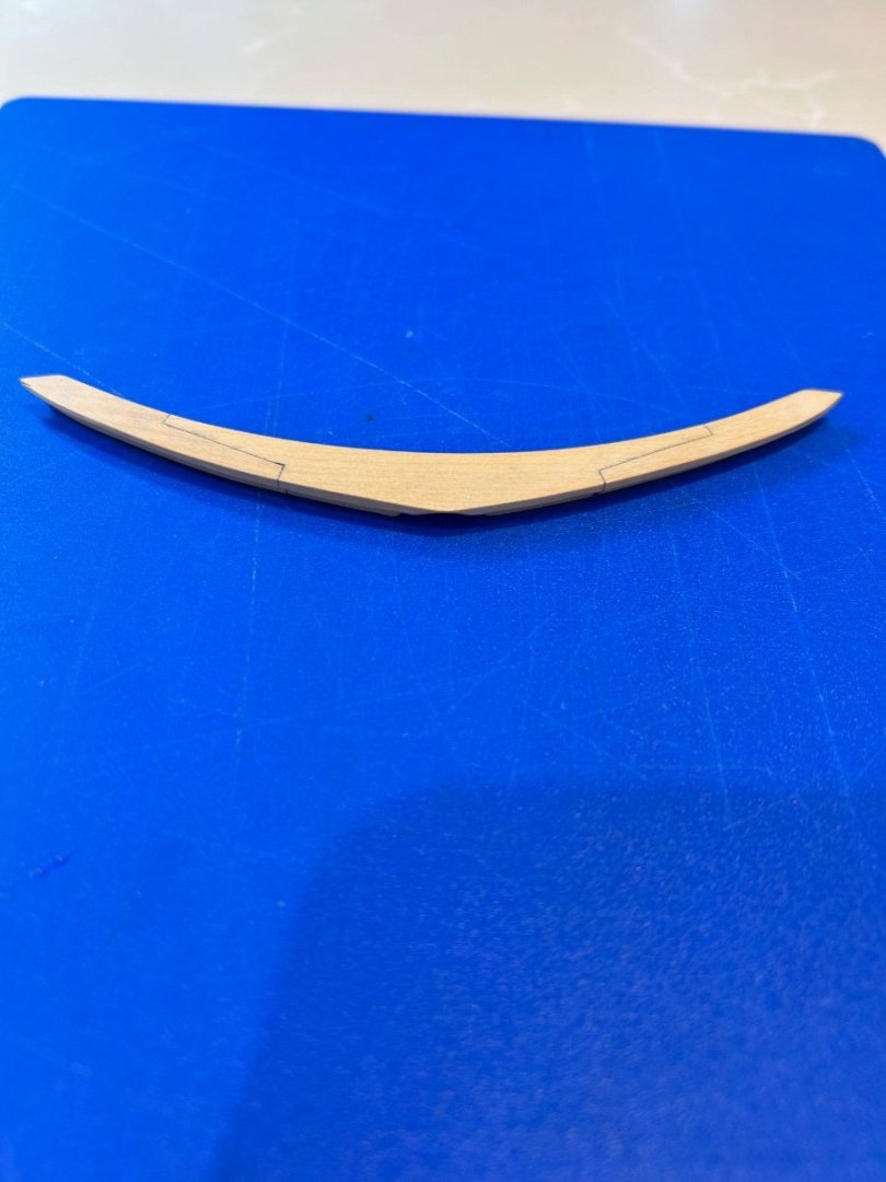
Then finally installation (btw this did take me 2 attempts to get right)
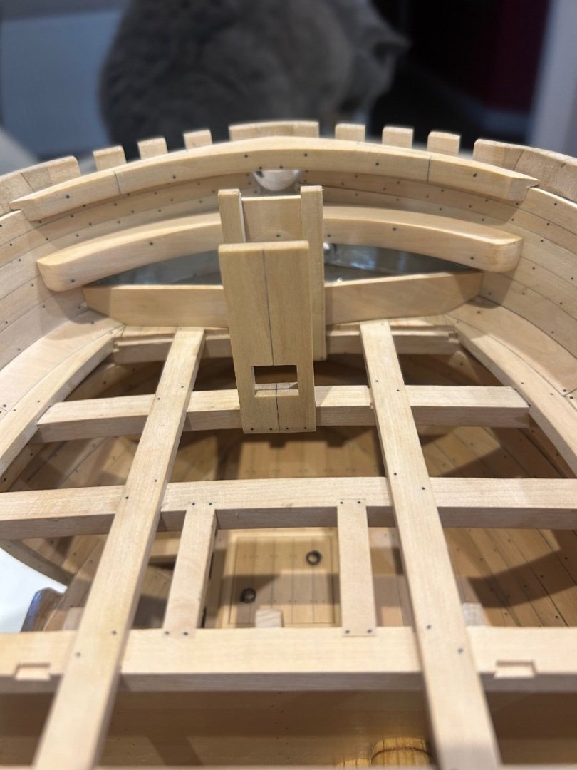

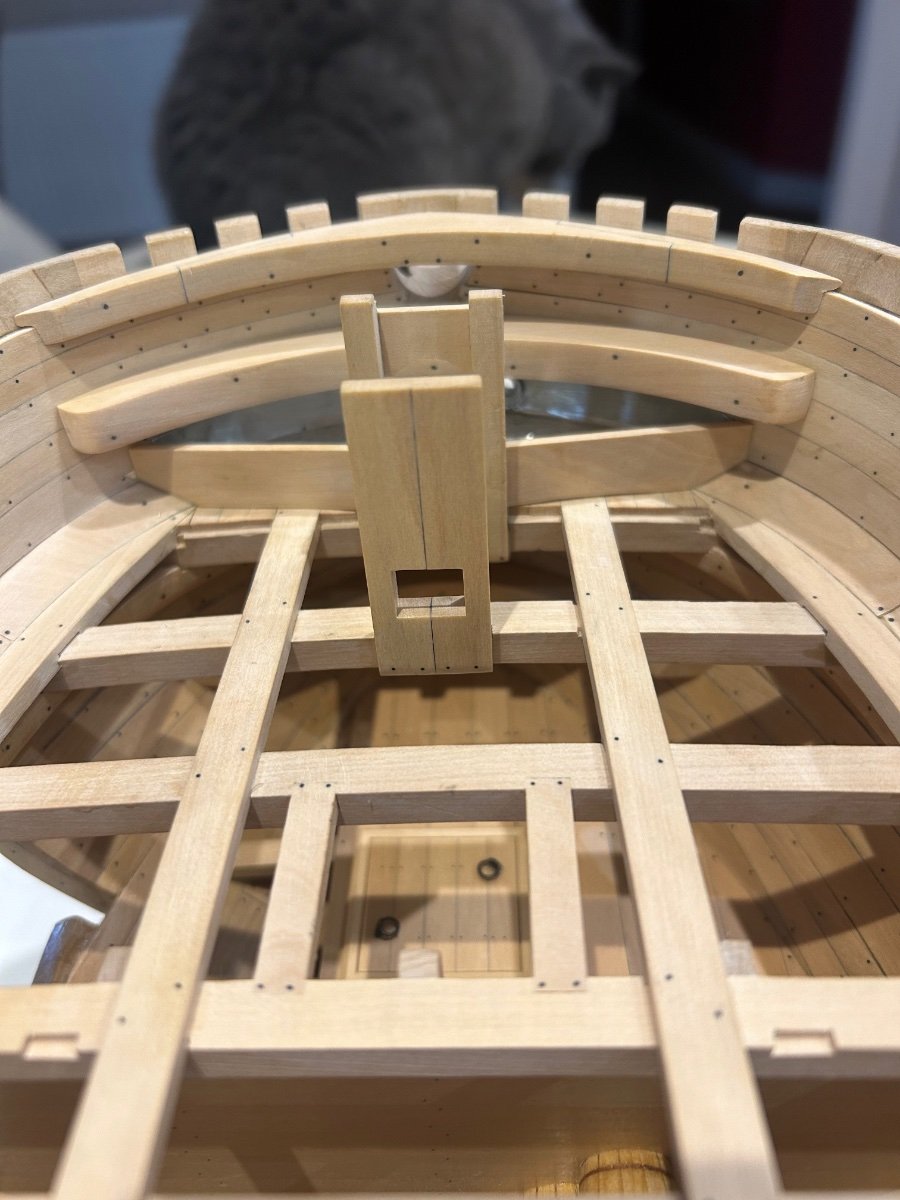
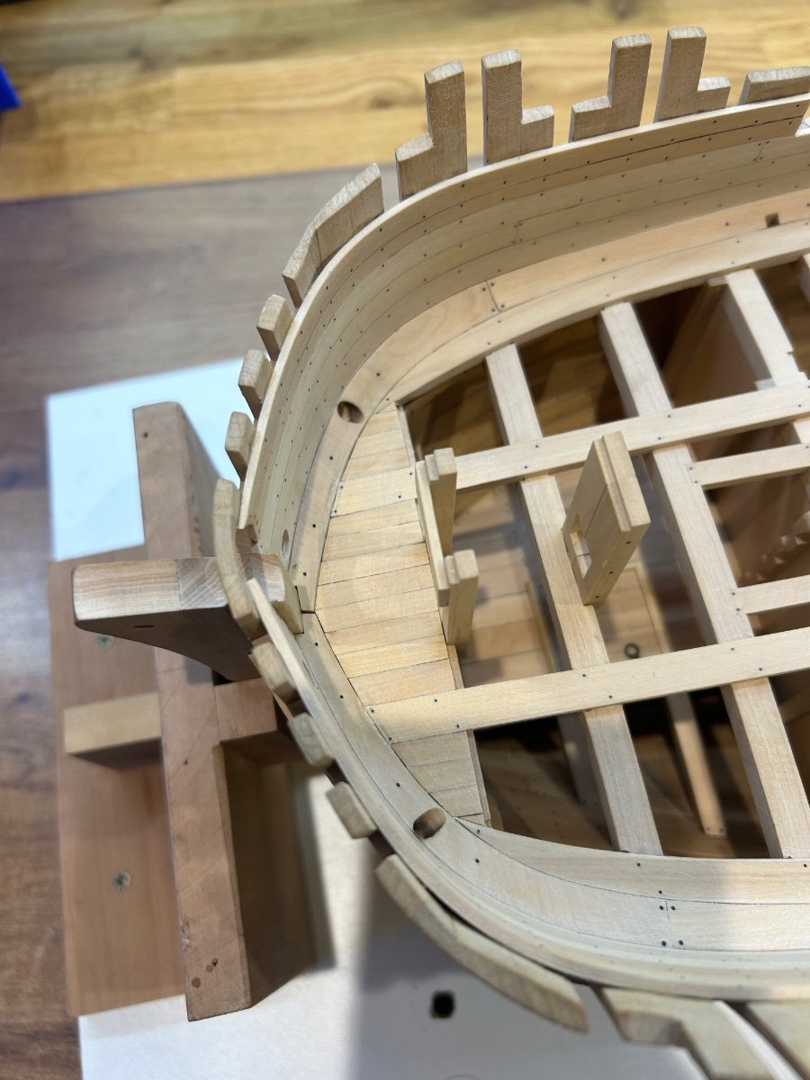
The bowsprit view which just needs a little fettling to bring it all to the final diameter. You will notice that there is a small gap between the clamp and the breast hook. One of the spin off benefits of making this part as accurate as possible is that it has put the correct curvature on the model for the forward deck.
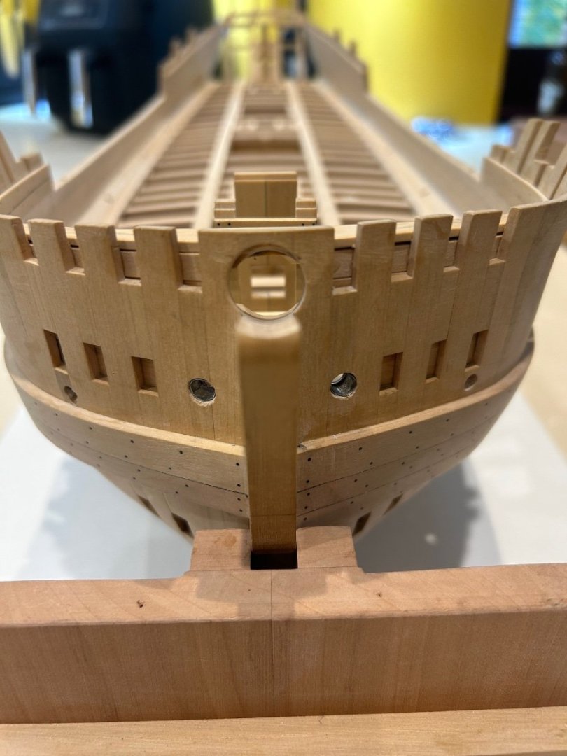
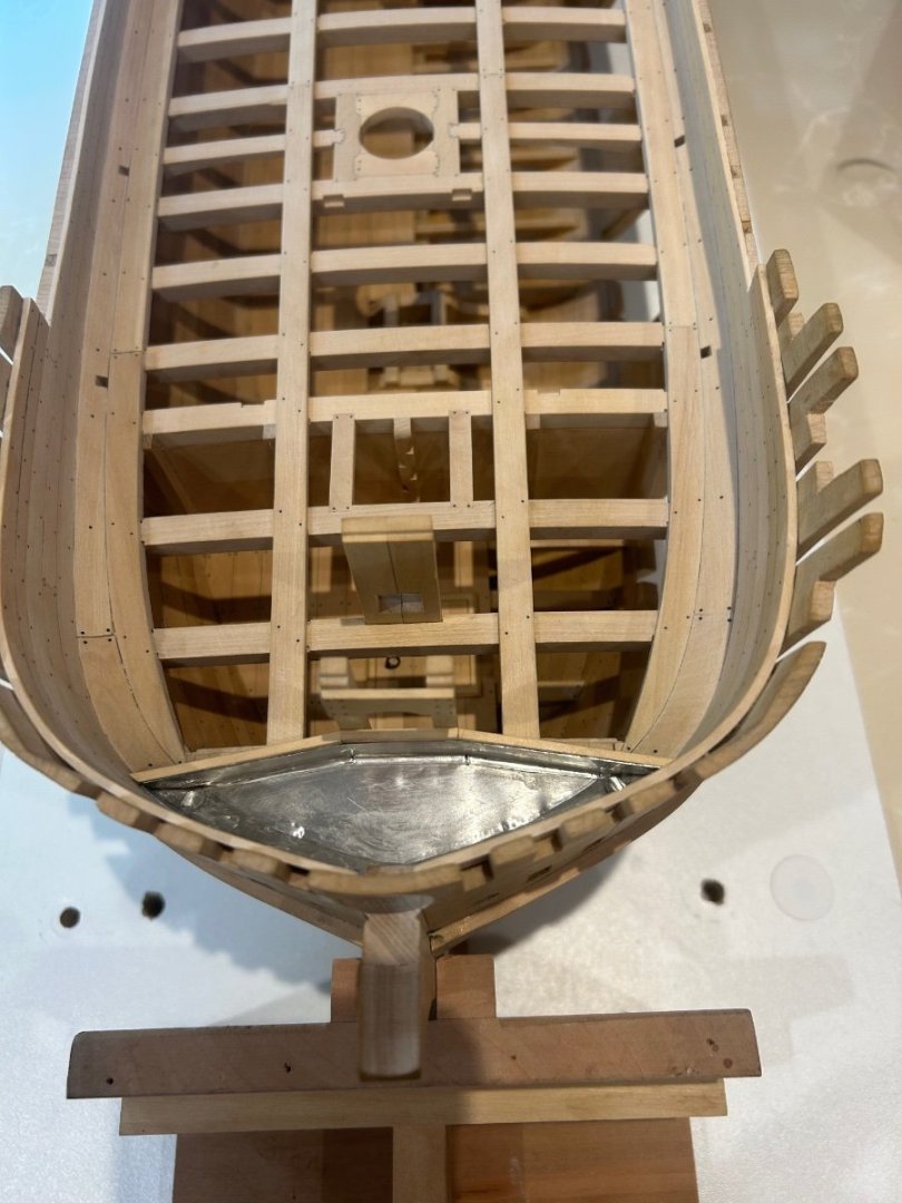
Finally one of my most favourite pictures of my build so far - just a little tidying up needed.
Now I was going to start planking the outside of the hull next but I have realised that the bowsprit partners are a little vulnerable. So instead I've decided to finish the forward deck first. So I need to make the small office and the ships stove and quite a few other parts too. I want to get the forward deck beams in before attempting any planking.
Can't thank you all enough for the likes, advice and encouragement - cheers Mark
-
1 hour ago, mgatrost said:
Wow, Your attention to detail is truly amazing.
Hi mgatrost - welcome to the build mate. Have a look on Ancre's website at all of their monographs. The attention to detail that the draftsman/historians/madmen put into their works are amazing. I feel that I need to do their work some kind of justice even if this my first scratch build. Thanks for your comment but have a good look around the forum as some of the builds here are truly amazing
")
- Keith Black, mtaylor, druxey and 1 other
-
4
-
1 hour ago, DaveBaxt said:
Really nice work shaping the pewter and looks amazing. Scuppers are another level of excellence.
Thanks Dave I did learn quite a lot from this exercise. Pewter is great to work with but cannot be soldered (I tried). I also would not use cyano again either - the lumps you can see are hardened glue underneath the metal which would not smooth out. Otherwise the finish would have been better - next time I will use 15 minute epoxy very lightly spread just to give enough time to get a better fit. As for the scuppers I couldn't believe that the jib actually worked! I though that the pewter would loose its roundness when sanded but it stayed as it was. I'll take that as a win
-
-
Hi All
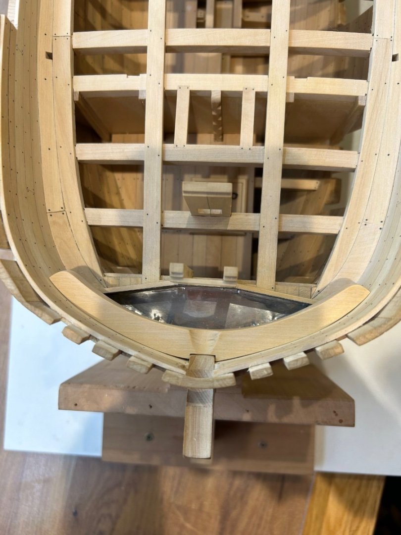
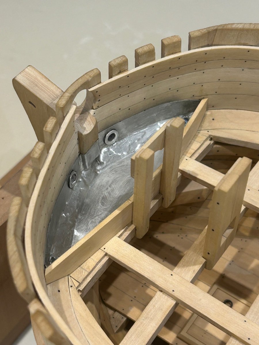
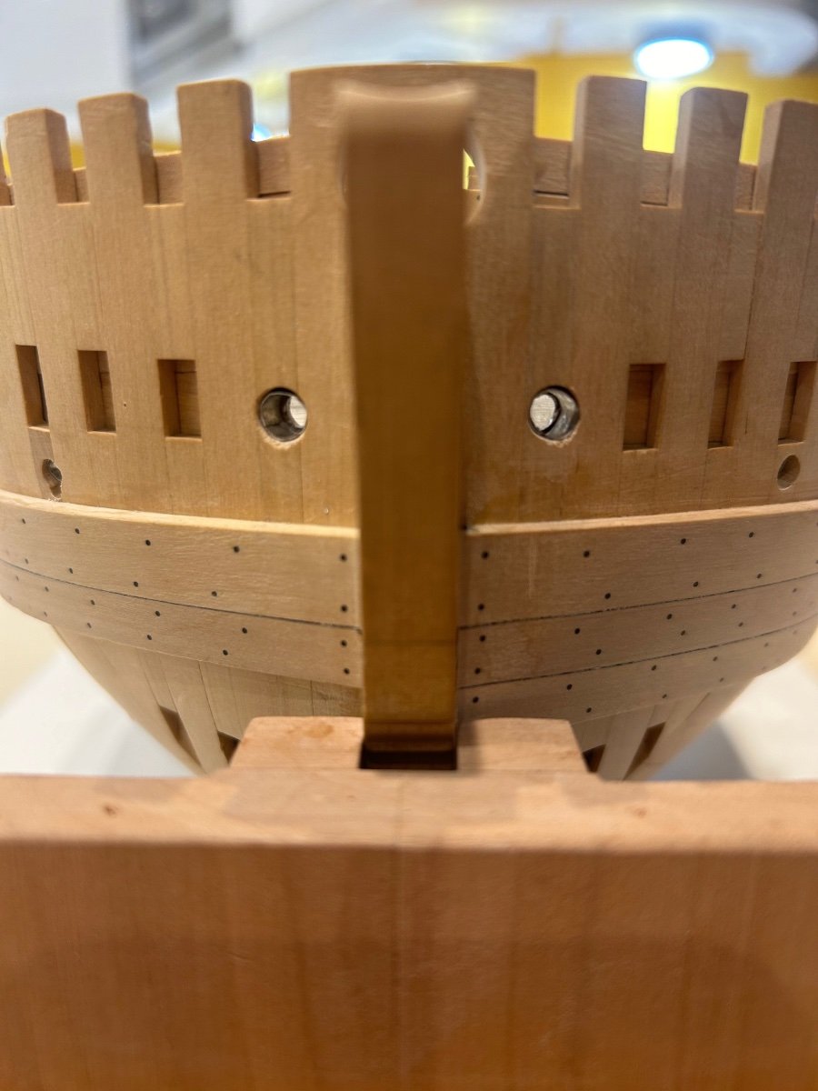
Some more done on my build - I decided to move to the front of the ship and make the bowsprit partners and the manger. The first job was to make the metal liners for the scuppers as once the partners were in place this would reduce the space in this area.
Having read the article on using lead in model ships I opted for pewter or as some places call it brittania. The sheet I used is 0.15mm in thickness and I needed to find a solution to the angle of the scuppers.
First I made a tube 4mm in diameter that would fit snuggly inside the scupper hole.
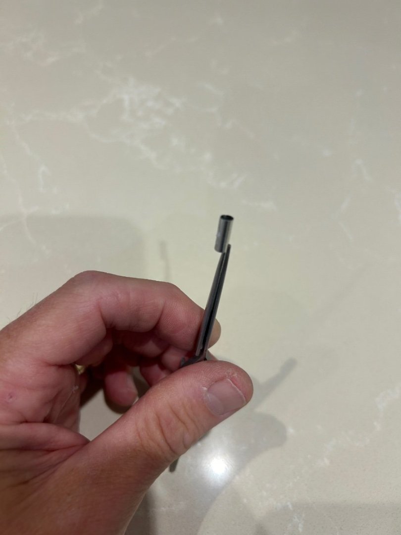
I then made a simple jig to match the angle of the scuppers. This allowed me to place the tube inside and carefully sand the tube on a face sander.
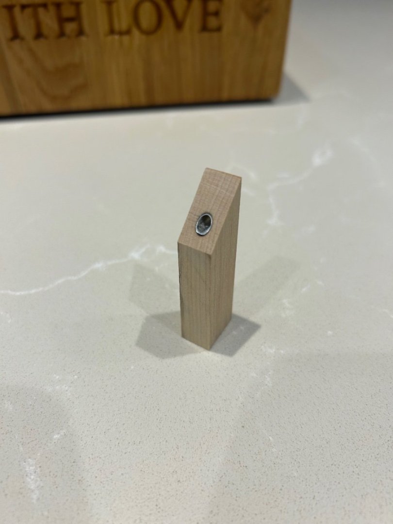
I then needed to roll the mouth of the tube over slightly to create a lip to stop the part from falling straight through the hole in the hull.
Then it was simply a trial fit and repeat for the other side.

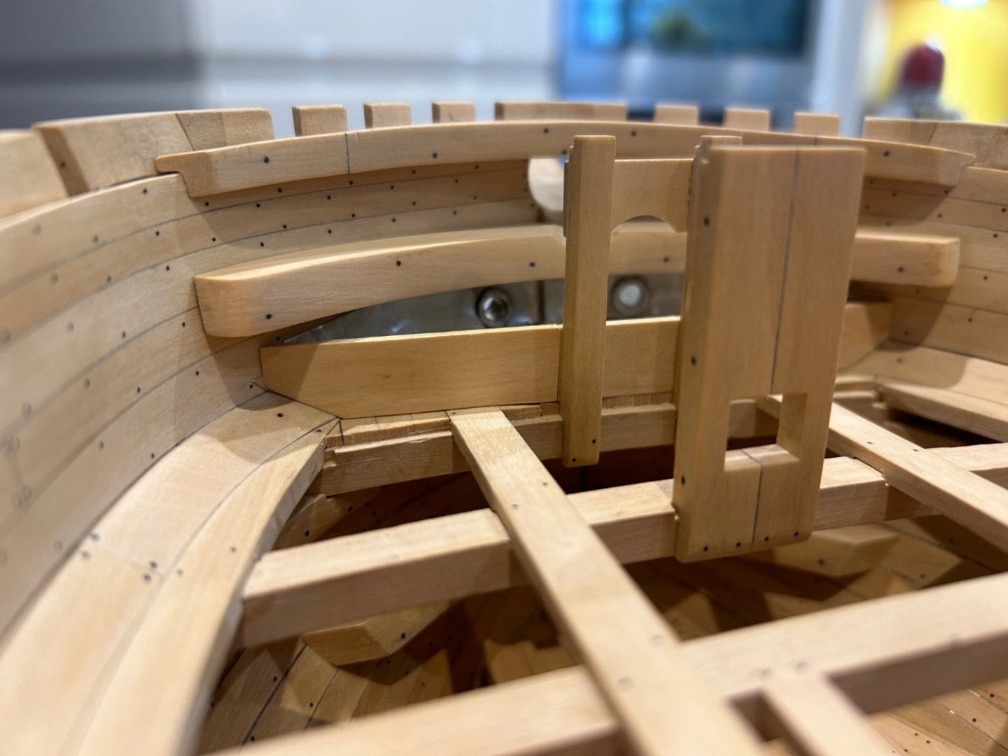
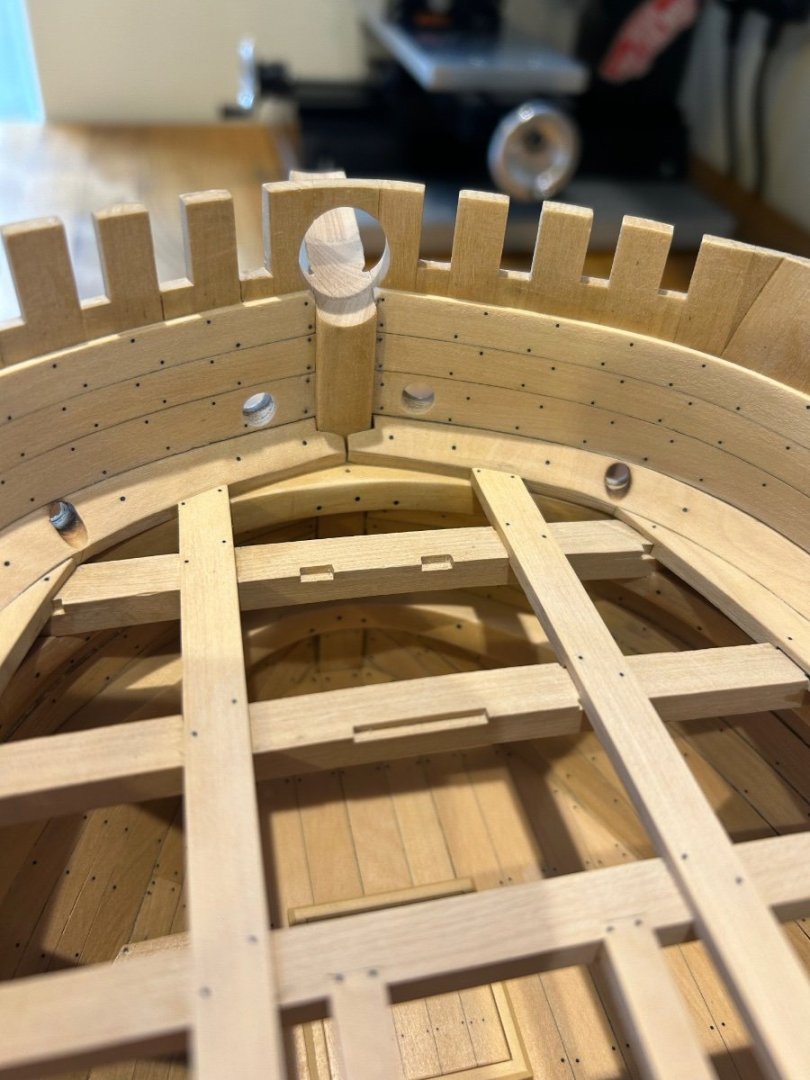
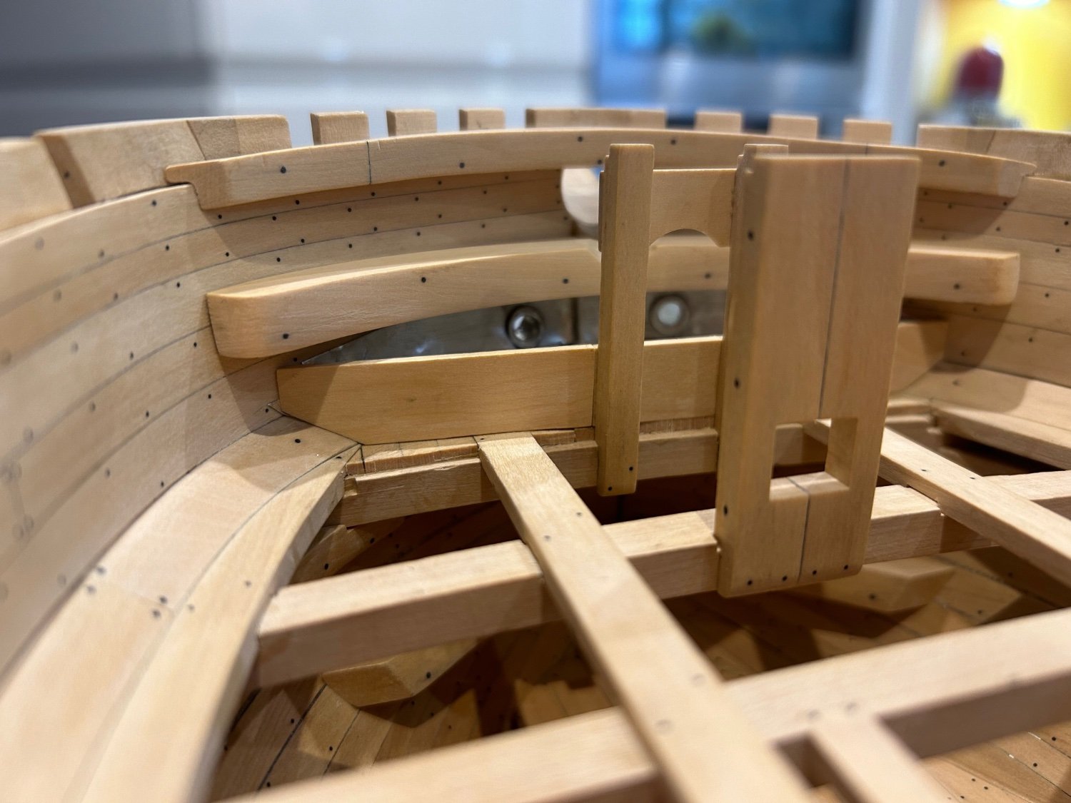
Next I made the two bowsprit partners.
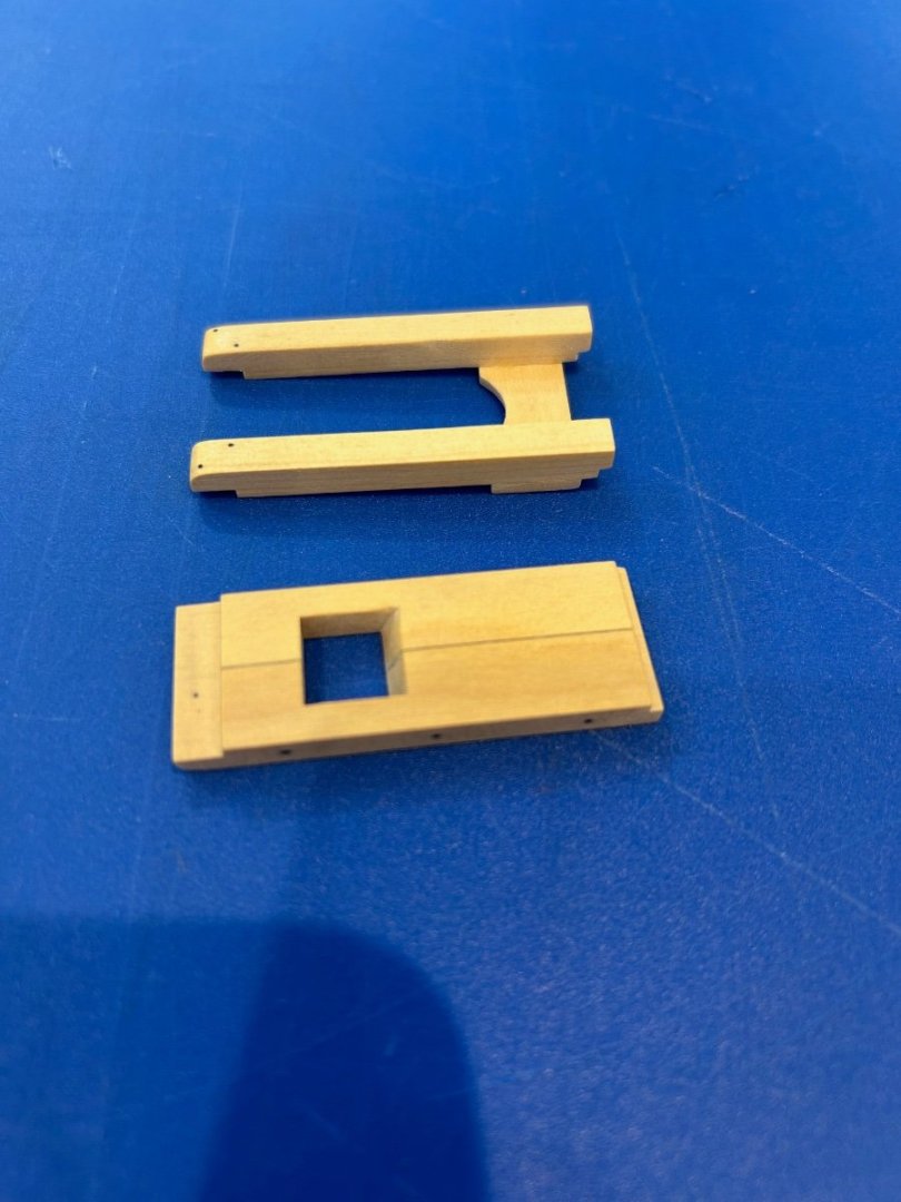
Now making them was a whole lot easier than fitting them. They fit into slots that I had previously cut into the beams and they have to line up precisely. The reason being is that not only do they need to be inline with the bowsprit, they also tie into the beams of the deck above. It's not too difficult I just had to check the overall height of these pieces before gluing.

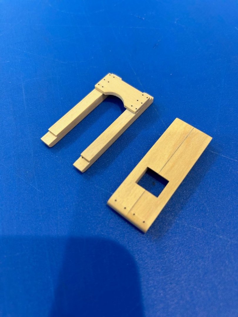
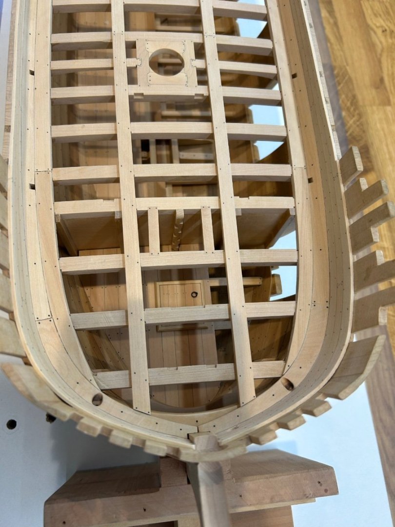
Then it was onto the manger itself - I have decided after all not to plank the main deck. I did though need plank the area for the manger.


I then made the back walls for the manger and pretty much got on with lining the whole thing with the pewter. I think that the results are ok - but just ok. I do like the way the scuppers just sit nicely in the corners as they should. I used cyano to glue it in and I remembered why I don't use this glue. I personally just cannot get on with the stuff.


So my next job is to make the final 2 breast hooks for the bow.
Cheers Mark

- Paul Le Wol, Ainars, GrandpaPhil and 23 others
-
18
-
 8
8
-
-
Hi Kevin what a great job you have made of your carvings. Its something that I must learn too and I wish we could get some workshops here in the UK as I would attend.
You have a Foredom so have you tried these? I put 6 into a mandrill and they work great for polishing wood.
At 1200 grit they would smooth off your carvings without changing the shape
Mark
- Ryland Craze, bruce d, billocrates and 1 other
-
3
-
 1
1
-
-
I think that the first 5 builders of the POF model are getting a very good deal here. Having scratched a frame in Castello I would estimate that the wood alone cost at least £300 ($400). This is the real deal and what a lovely ship this is going to be to build
Not only that you know that its going to go together perfectly and also get the back up of the manufacturer right here. In fact I think the first 5 builders will be more than lucky and I can't wait to see their builds on here!
-
1 hour ago, Toolmaker said:
Hi Mark,
Do you have a link for a supplier of these. The company website is unclear.
Thanks
Paul
Hi Paul
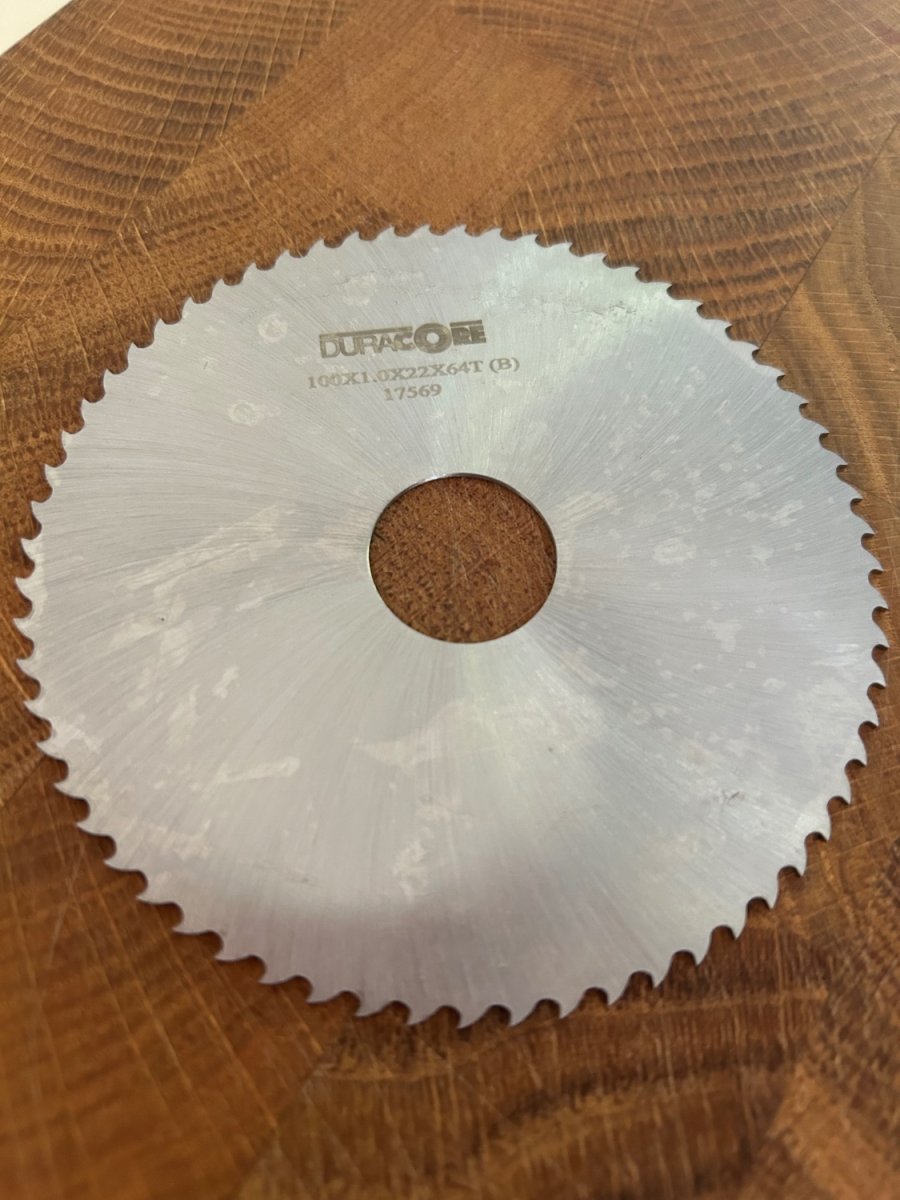
I did post this but I must have done something wrong. Here’s the link you need but remember it does have a 22mm hole so a new arbor would be needed but Jim can supply them.
https://www.protool-ltd.co.uk/p/17569
Cheers Mark
-
Hi Thistle17 - fence alignment is very important and also really easy to do with a DTI. Since my last post 8 months ago I too have had some issues with thick wood overheating and burning. As I know that my saw is set up exactly it could only be the blade. The 110T blade can bind up quite quickly so I swapped it for a 64T blade. This got the chips out much better and solved my problem. In fact this blade goes through wood like a knife through butter. It also leaves me a good finish on the cutting edge with virtually no chip out. I’ve also noticed that the motor runs a lot cooler too. This is now my go to blade for ripping planks.

- Canute, mtaylor and Ryland Craze
-
3
-
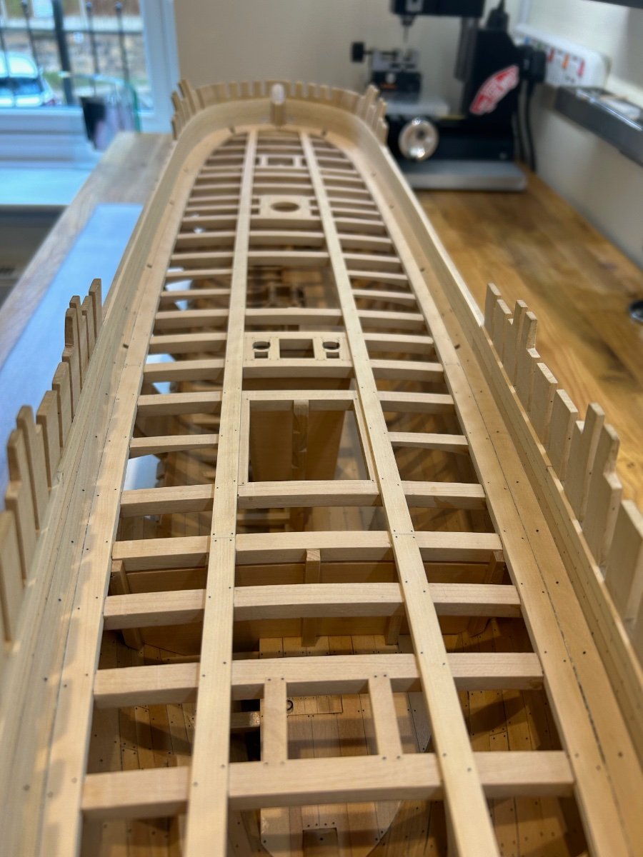
Hi All
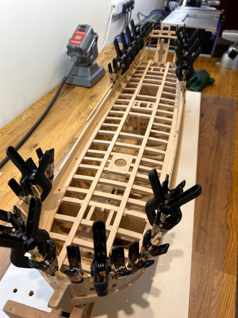
Time is not a friend of mine at the moment but I have been watching others build projects (enviously 😆). I have got some done hence the update and thanks to everyone that took the time to give advice and the very lovely comments.
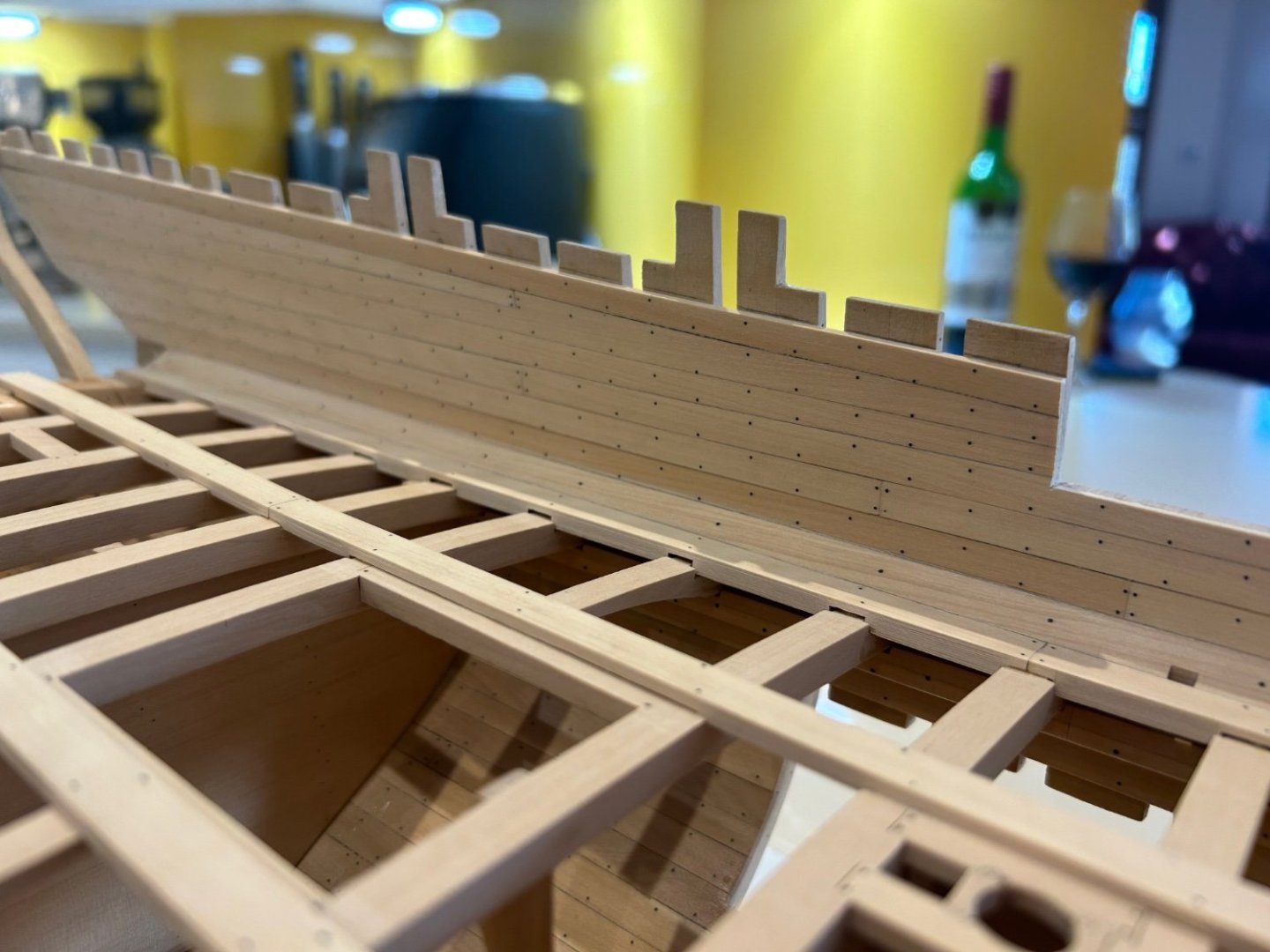
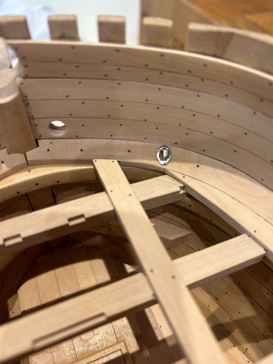
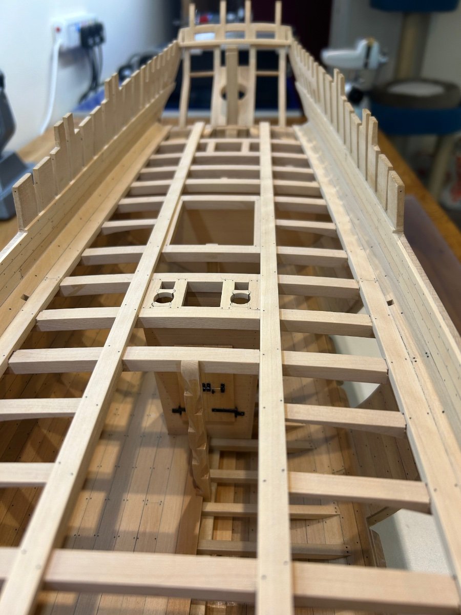
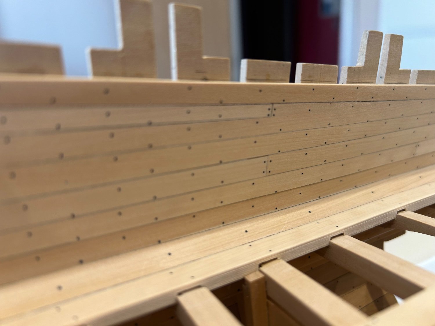
The first thing was to fit two more plank strakes on the bulwarks and then pierce the holes for the scuppers and hawse holes. Nothing really tricky about this you just have to be careful cutting the holes so that you don't tear the wood too much.

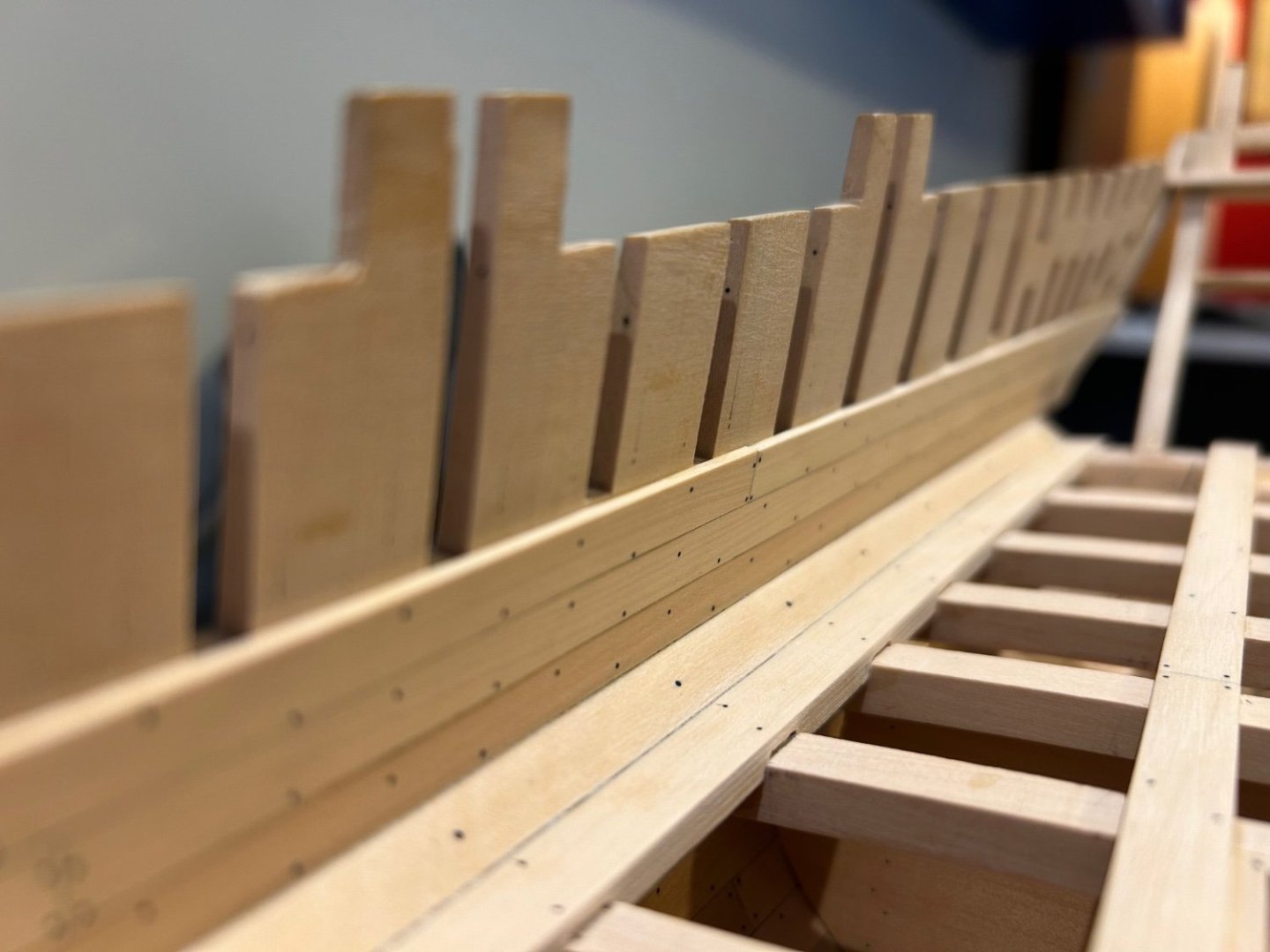

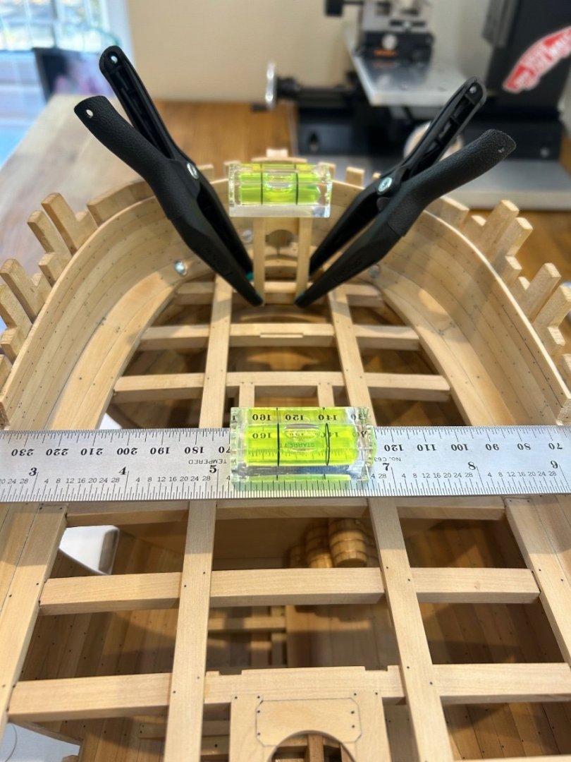
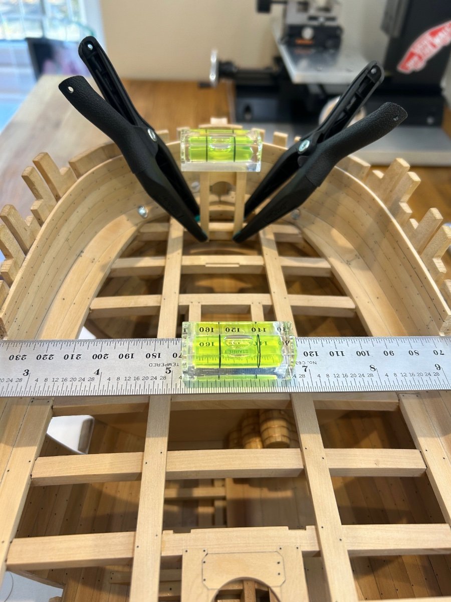
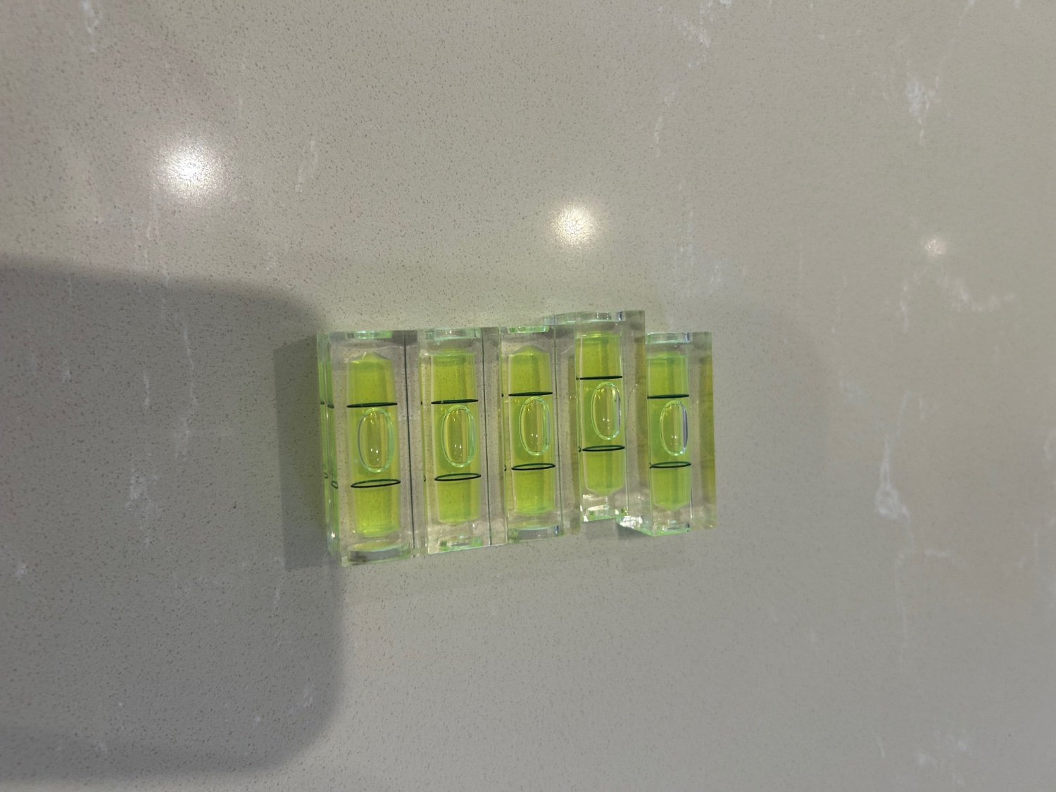
Next was to make and fit the deck clamps for the smaller aft and forward decks. Learning from my previous attempt at placing clamps I really took my time marking these out with a digital height gauge. I think this took me about 4 hours to get right until I was absolutely happy with their placing. I also used a technique that @Tobias uses with tiny spirit levels athwartship. These things are so cheap and yet they allowed me to checked my levels even further. I used quite a lot of clamps to make sure that my efforts stayed where they were. Cheers Tobias

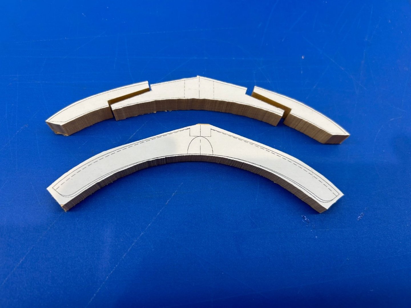
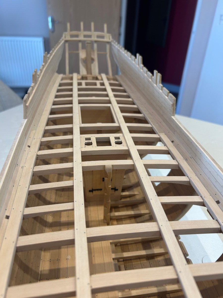
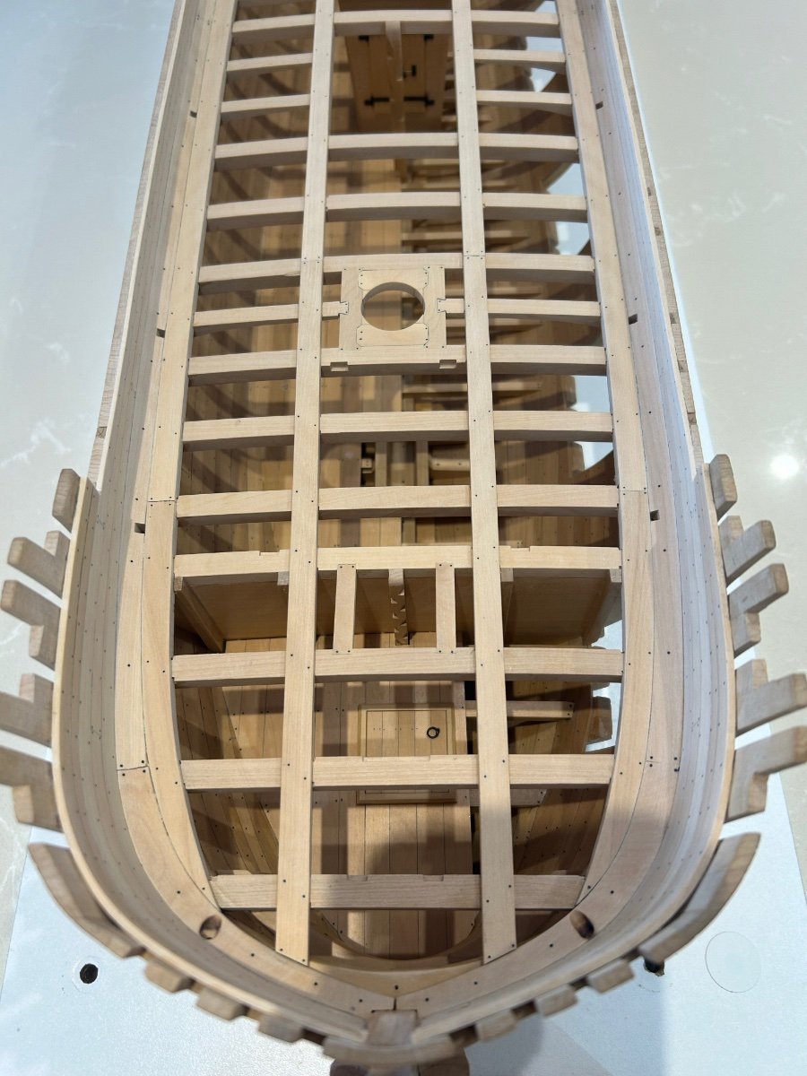
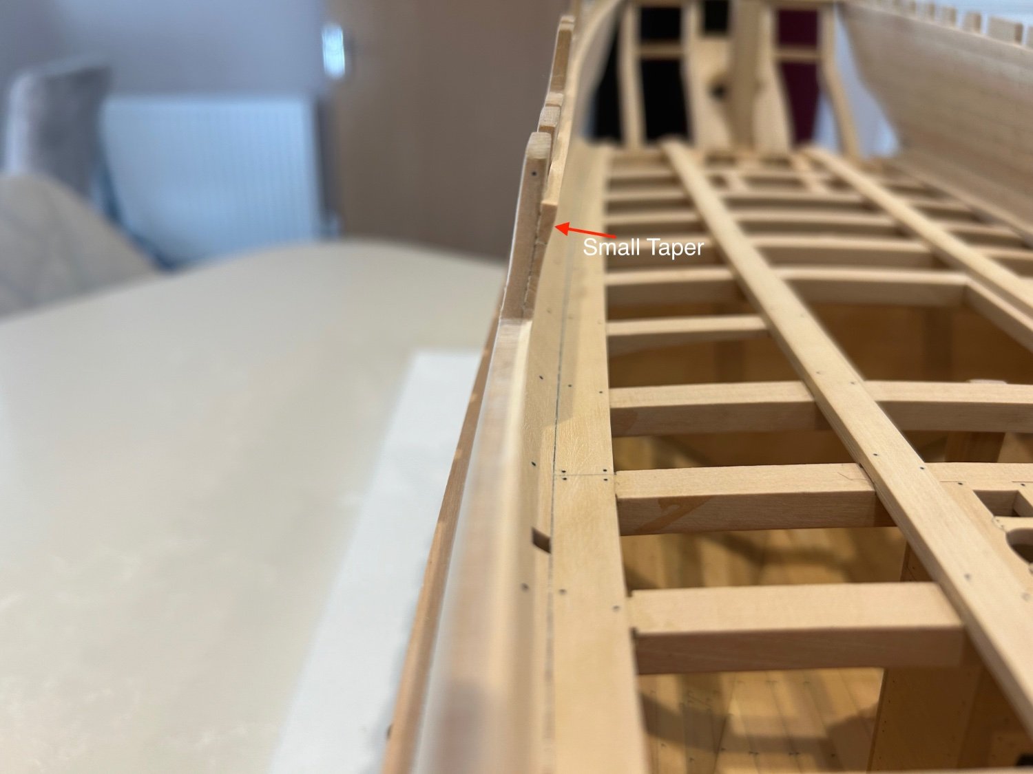
Next was to plank the gap between the already fitted planking and the clamp. All I would say about this is if you measure and plan it accurately it's a fairly straightforward job. I can imagine it being a nightmare if you don't. The clamps are slightly thicker than the planks and just need tapering into the planks below. I've put a photo below to show what I mean.


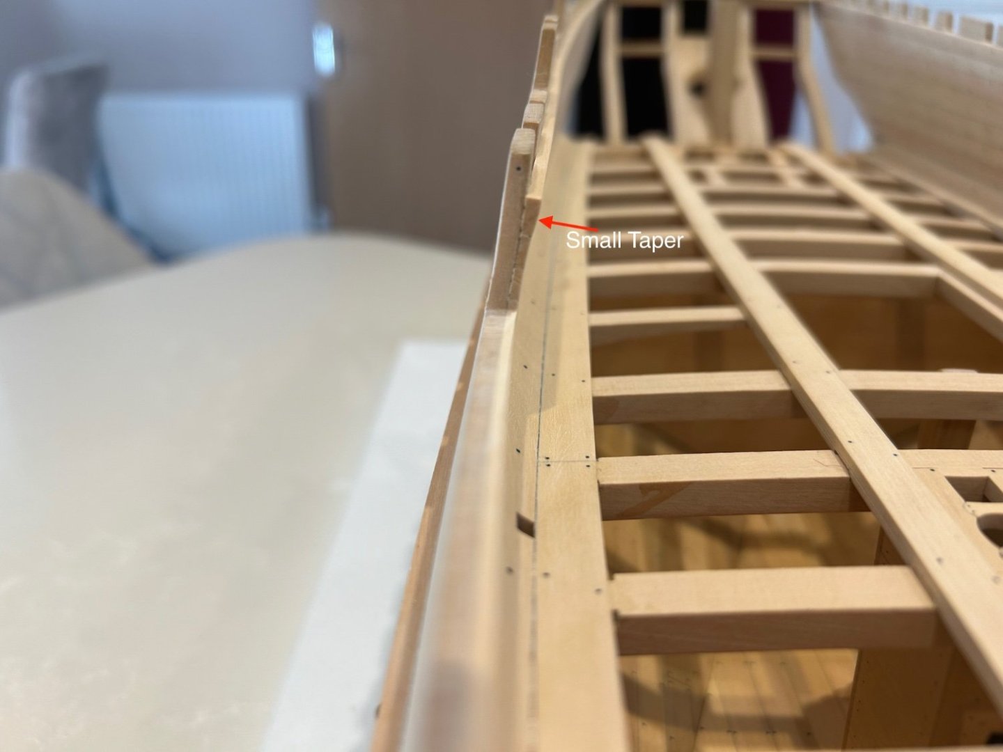
Note to self - use a lower resolution camera as these photo's show everything
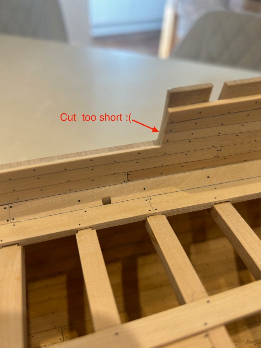
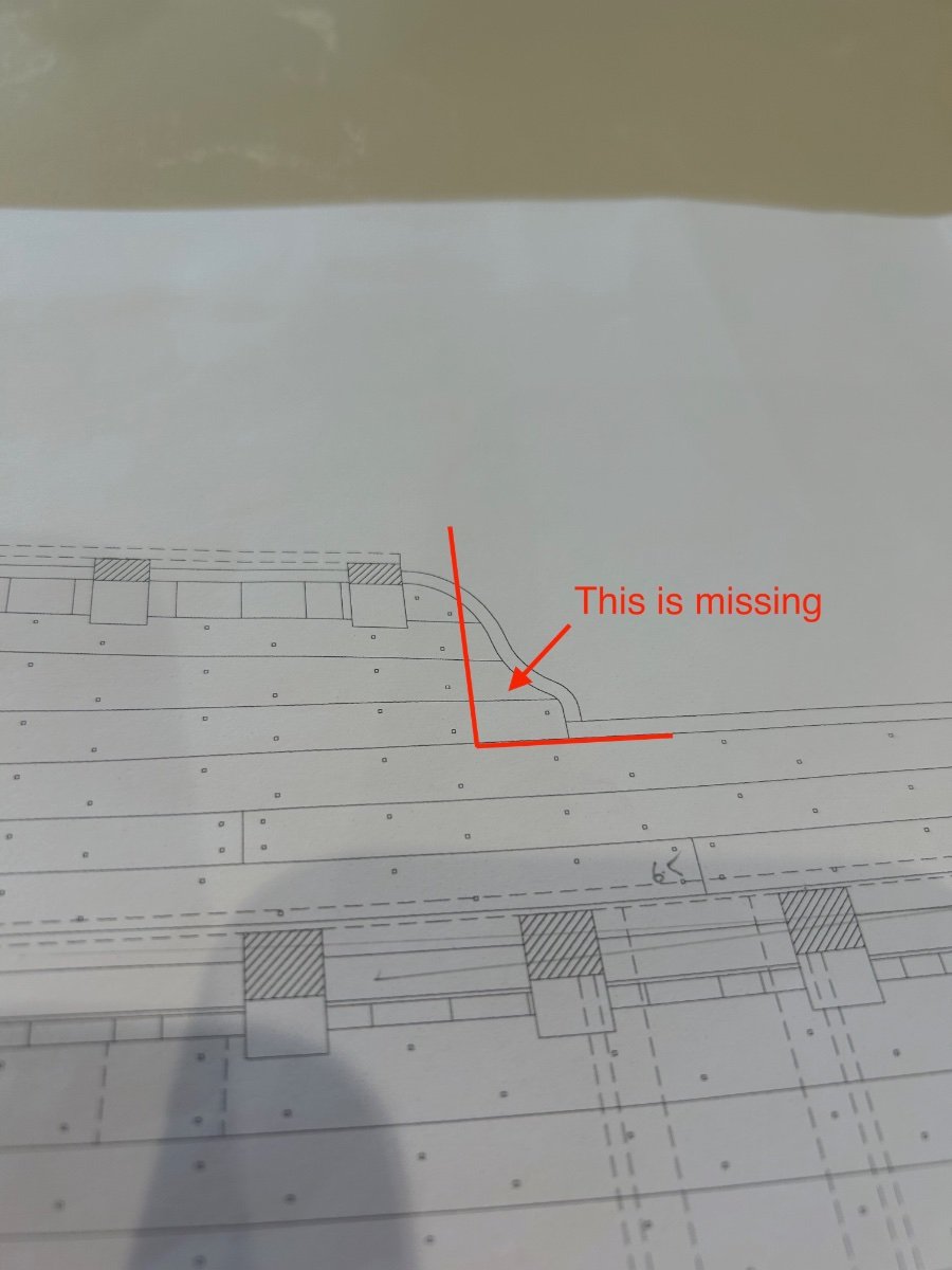
Ok so as always - what did I do wrong? Well I cut the planking too short - Its not a problem but I forgot to allow for the scroll to the gunwale.
This is how I cut it.

And this is what I missed
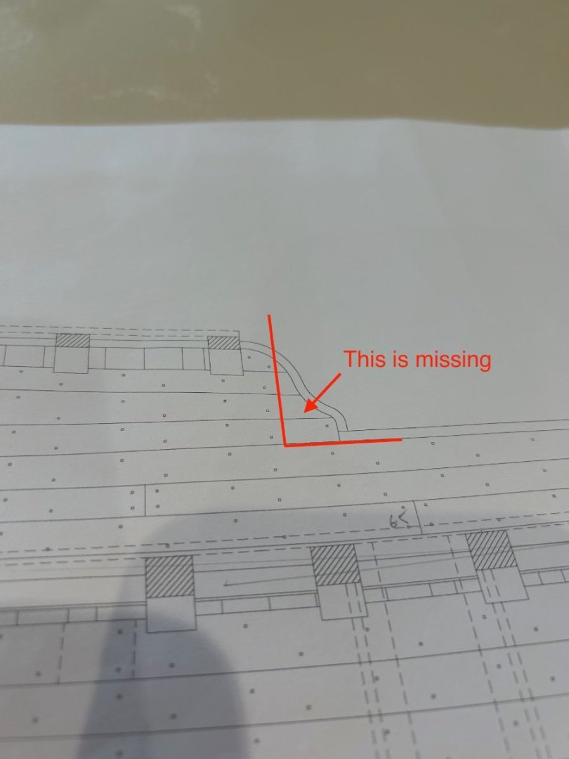
Its not a problem as I will fix this later on when I plank the outside but for fellow builders this could save you from doing the same.
I'll get some more done as and when I can - I think I need to be retired so that I can enjoy my hobby more!!
Cheers all - Mark
-
Great new workstation - There's nothing better than having a nice place to work.
- mtaylor, FriedClams and Hubac's Historian
-
2
-
1
-
-
I have to say Chuck that I really like both types of block......beautifully made and if a builder gets a choice of colour then thats even better!
- Canute and thibaultron
-
2
-
-
On 7/5/2023 at 3:22 AM, Guyuti said:
Hi,
I am looking to buy a 18 inch Byrnes Table Saw. I have not used one for many years and have never owned one, however I would like your advise as to what parts I should buy with the basic saw to make it perfect for scratch building. i am looking to eventually build a first rate in 1/48 scale and will be ripping my own planks for decking and hull. As I live in the UK getting all the parts in one go makes sense due to custom and postage costs. Can anyone please tell me what Should i buy :-
Sliding Table Auxiliary Tilting Table Extended Rip Fence Miter gage Adjustable Extension ] Rip Taper Gage Micrometer Stop - inch Micrometer Stop - Metric Miter Bar Zero-Clearance Insert
4in. Carbide Blade 24-tooth - .055 kerf 4in. Carbide Blade 36-tooth - .055 kerf 4in. Martindale 110T-.04 kerf Slitting Blade (recommended for use with the Tilt Table) 3 in. Martindale 90T-.04 kerf Slitting Blade 3in. Martindale 90T-.03 kerf Slitting Blade [pic] 3in. Martindale 90T-.02 kerf Slitting Blade 3 in. Martindale 90T-.023 kerf Slitting Blade 3in. Martindale 90T-.028 Slitting Blade
Replacement Miter Gage for Saw Replacement Belt Accessory pack (Extra miter pin and all the removable screws)
Thanks in advance
Guy
Hi Guy - I have pretty much ordered all of the above for my saw and I use everything that I ordered too. Over the past few years I have found that a UK builder should order as much as possible as the shipping costs here are very expensive.
So here is what I have learnt as a UK builder - I don't use carbide blades for anything other that cutting down big pieces of wood. The edge finish is rough and not suitable for modelling. Also if the piece of wood moves even slightly sideways as you are feeding it through, the blade will cut sideways and leave you with a piece of wood that varies a lot in thickness through its length.
Buy at least two accessory packs as you will loose screws and its a bargain for us. All of the threads are UNC which we do not use here.
We are metric here so go for the metric stop.
Get as least 5 - 6 zero clearance inserts - They are as cheap as chips and you will need one for each thickness of blade. You will accidentally fit the odd bade incorrectly as it will trash the insert. Get some spares.
Buy a couple of belts as they do wear out over time and you need to think of the cost of shipping one here.
Buy as many blades as you can! I use three types of blade now. The 4" blade for cutting planks as it had much less deflection and the 3" blades for finer work. I go through a lot less of the 3" blades.
Regardless of how often you use these parts I have not regretted buying anything and I can honestly say that Jim and Donna Byrnes properly support their product. There's nothing better that I know of in our hobby and I'm very glad that I have mine
Mark
- mtaylor, Guyuti, Snug Harbor Johnny and 2 others
-
5
-
I also thought the same as you - however when it came down to it I found it easier to correct the clamp. If both sides of the clamp are the correct height then you will get less roll on the beams throughout the length of the ship. Your idea can be done but you will end up doing a whole lot more measuring in the end. The clamps will look a lot more uniform too if you make them the same. We both had the same issue and same solutions to consider.
-
-
-
What a fantastic kit it really shows the details of the small area of a ship that it covers. This is the sort of kit that I would happily build as the results are great. A top tip for any UK builders though - If you have a Games Workshop near you just drop the figures into them with a few quid and ask them to paint them for you. What they can do is amazing and far better than any of my feeble attempts.


HM Cutter Trial 1790 by Dunnock - FINISHED - Vanguard Models - 1:64
in - Kit build logs for subjects built from 1751 - 1800
Posted
What a lovely clean build you are doing here - your ship looks fantastic 👍