Beef Wellington
-
Posts
2,249 -
Joined
-
Last visited
Content Type
Profiles
Forums
Gallery
Events
Everything posted by Beef Wellington
-
 Looking really nice Bob, can't believe I missed this build get started.
 -
I really have no excuse for buying, let alone starting this kit as I have plenty going on I my current builds. However, everytime I wandered over to the Syren Ship Model website to buy sundery items, this kit stared back longingly at me, and sadly up to now was 'out of stock'. Fortuitously on the last visit, there was one in stock and I just couldn't resist, after all, it couldn't hurt could it? Well, the package has arrived and despite my best efforts to leave the box closed (about 5 minutes), the genie is out of the bottle. This will most definitely be a side project, and it will finally be nice to be able to follow some very good instructions and build a very nice looking model out of the box. Hopefully this will be a nice diversion to 'Jason' which seems to be anything but. I hope that I'm up to this challenge, I can certainly appreciate the reasons why this is classified as a more advanced kit. Progress will be slow. I'm not planning on this being the most extensive build log, but will likely post progress pictures and ask questions as I go...
-
Great result, night and day difference Kevin. I really need to develop my skill soldering as well...
-
Hi Mark, I'm not very adventurous with colors, so have stuck to the Admiralty paints red and yellow ochre. I like the look of them, but of course colour preference is a very personal thing. I used the technique Druxey outlined, sealing the outside planking, painting carefully and then simply scraping off any excess - worked pretty well.
-
That's a really nice result Mark, looks great from here!
-
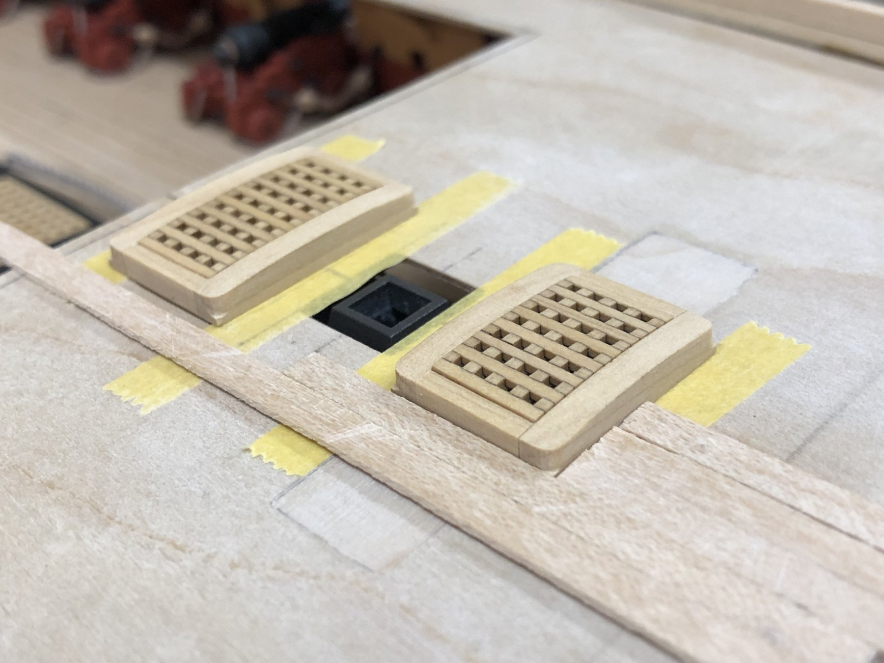
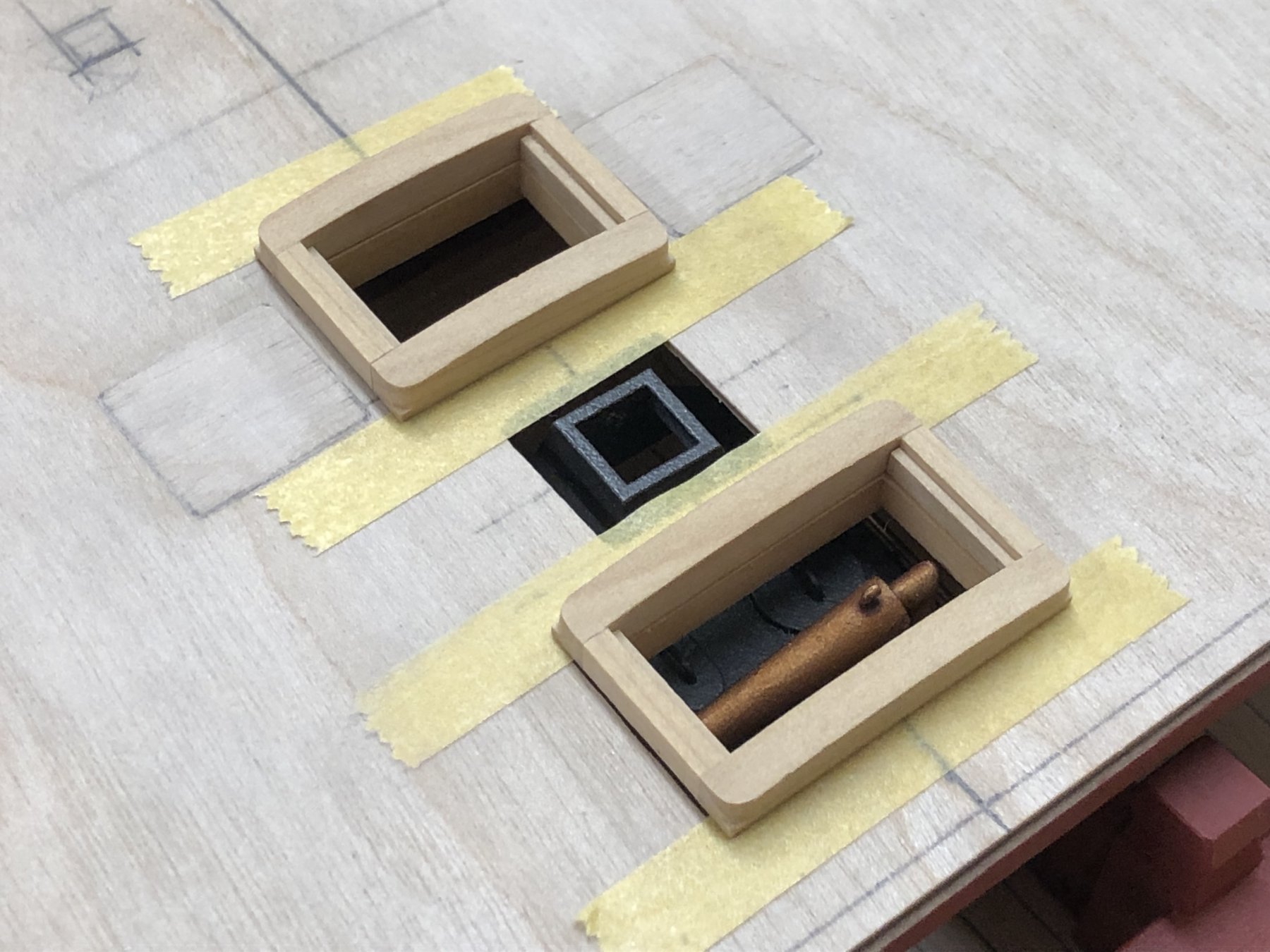
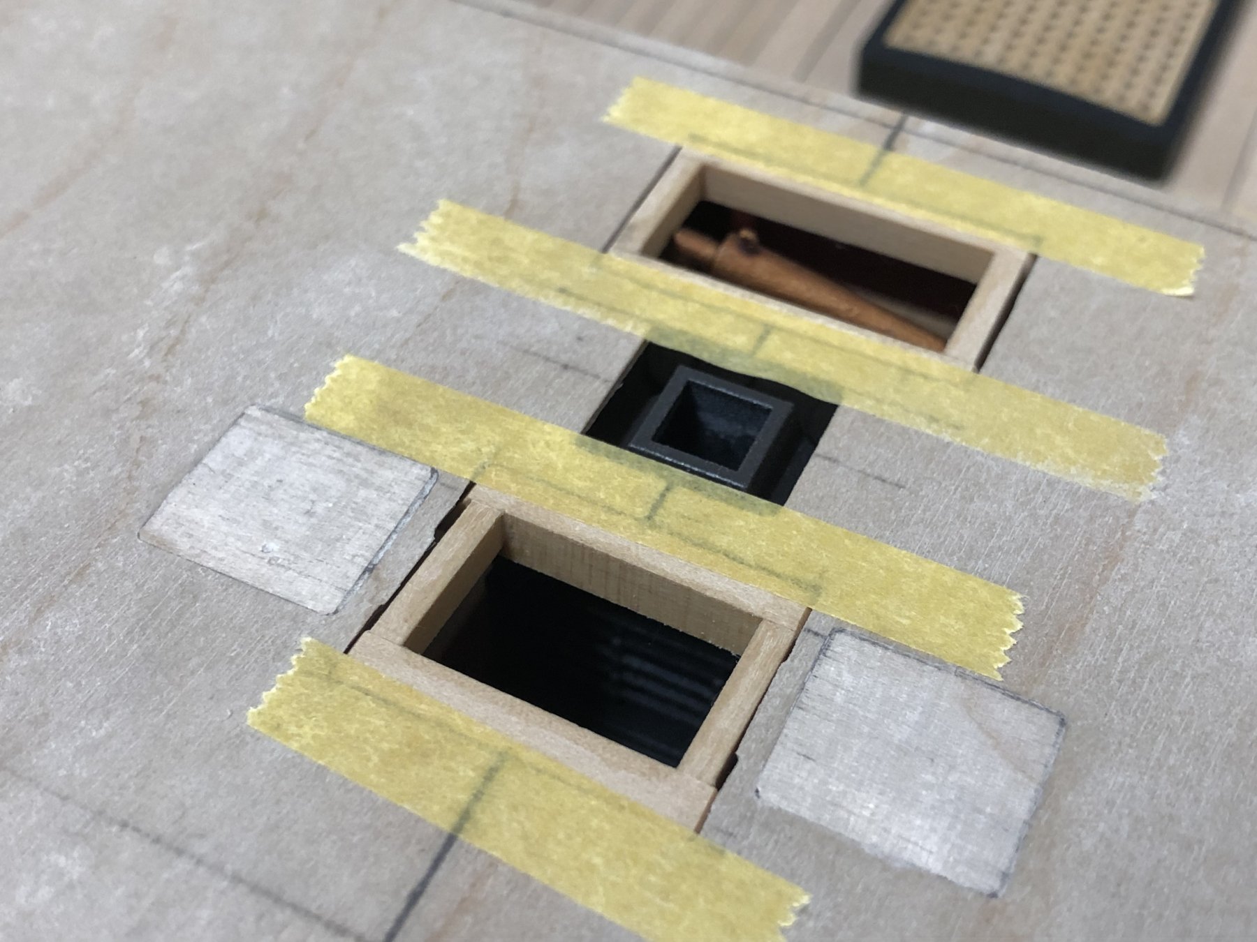
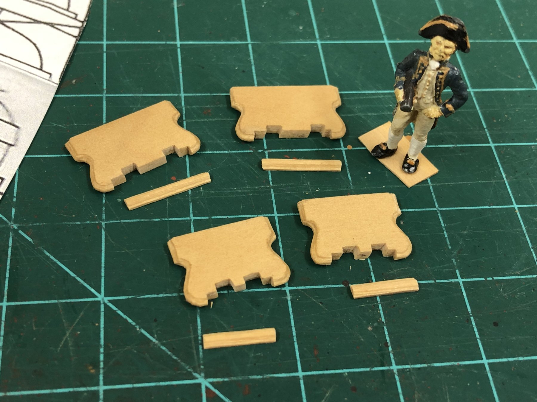
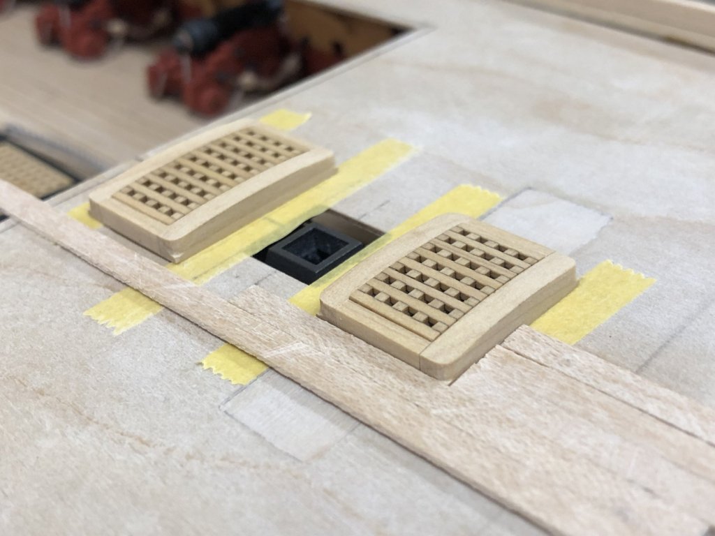
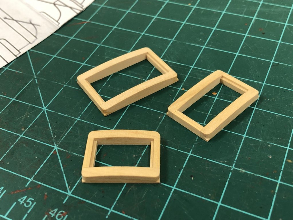
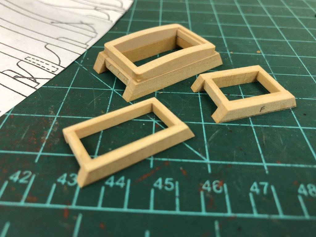
Quick update. Increasingly realizing I'm reaching a point that I need to attach the upper false foc's'l and quarter deck template before more progress can be made, but a couple of items I need to finalize and figure out first. Main and mizzen backstay stools: Unfortunately when I made the channels I neglected to make the stools at the same time, In a moment of focus decided to just get these done. These smaller items were definitely trickier than the channels when scraping the edge profile, other than that, these can be put aside for when I'm ready to install the quarterdeck drift rail. Upper deck coamings: As mentioned previously, I'd like to keep the option to have a few of the gratings be removeable. First off, appropriately sized gratings were made up, and the coamings then sized accordingly. I cheated here and used a simple butt joint as I didn't think the more authentic lap joint would really be visible. These were made of 3x3mm strip and 2x3mm strip with the inside ledge added after with some slightly thinned 1mm strip. The grating thickness had to be thinned quite a bit to make it them sit flush. These will also be simulating actual practice and so the edges were rounded off to 1mm above the bottom to butt up against planking. TFFM was used as a guide here. Once the coamings were finished, the fake beams and cross pieces could be made up to the appropriate size. The ends were sloped to ensure that the end of the face beam would not be visible for viewing angles. Adjustments were made to the false deck to accommodate the larger openings and positions tweaked a little. For the foc's'l, the coaming size does not match the deck cut-out or AOTS exactly due to the limited incremental options for the grating size. The stove flue needs to sit equidistant between the steam grate and the forward grating which moved forward slightly. The steam grating needs to be positioned appropriately to allow the belfy to sit on the aft end of the steam grate coaming. The top tackle scuttles have been filled in to ease future planking - the instructions indicate that there should be coamings and gratings here, however, these will be modeled as flush scuppers without a coaming as described in AOTS and shown on contemporary models. Although the surface of the center deck is very slightly curved, it is a close enough approximation to a flat surface that the flat top of the fake frame seem to sit without issue. Lighting is clearly an issue here, and the interior is a little more visible than the photo's suggest, and probably more so in a well lit room. Of note is the fact that the stove, and especially the condenser, sits a little higher than ideally would be the case, although looking at the AOTS diagrams its still a tight fit there as well. In retrospect, I would probably not have put wooden battens underneath the bottom plate to lower this by 1mm or so, but not going to risk damage at this point to redo. Putting some scrap planking in place give a better sense for the final proportion and the above deck rounded edge. Think these will be a nice contrast to the much higher coamings of the exposed upper deck below needed to withstand water ingress.


-
Hi Candice, You did better than most as a first try on the first planking, your solution to the sunken plank at the bow is a good one, the soft lime wood is pretty easy to sand to shape, and I suspect that some sanding to shape at the bow will smooth everything up. Your efforts on the first planking will definitely pay off in a much easier and enjoyable second planking. Something to check as it is difficult to tell from the pictures - did you thin down the false keel at the stern (called 'bearding')? The 2 kits I have experience with (both Caldercraft) require the false keel at the stern to be thinned, so that by the time the first and second planking is applied the surface should be nearly flush with the walnut sternpost that still need to be applied. Otherwise the you'll end up with a significant step when it should really be a smooth. A suggestion for the future. You way want to consider cutting a rabett into the bow and keel (it is described in the 'pinned' planking tutorial in the planking section), basically its a small groove that the edges and ends of the planks fit into and definitely helps getting a nice curve. I didn't do this on my first build (Snake), and although it worked out OK, I'd definitely recommend trying it next time. Jason
-
I think the method of building up the wales as you are doing to more preferable and would suggest doing the same on Snake and Diana, which both suggest planking wale over second planking - both are the oldest CC kits I believe. On quite a few models you see the run on the second layer planks and the wale crossing over each other which to my eye now looks awkward. This is more in line with how the wales would be done on a framed model, and allows you get a nice finish on the wale first, and a nice foundation for the run of the second planking.
-
As a kid I always remembered staring up at this kit with longing eyes, it was always sitting out of reach - physically on the top shelf, and financially in its huge box! Never seen the PE before, so definitely want to follow your progress Kevin, this is the first PE I've seen that needs to be soldered. You're doing a great job.
-
That is some seriously good first planking, well done!
-
Hi Vane - Looking good. The trick with the wale it seems is to have it parallel to the sheer of the top of the bulwarks and all of the various rails. Once you see it it seems so obvious but is very apparent from looking at original plans, but I completely missed it on my Snake build. Given that you have these preformed, it should be possible to use that as a guide.
- 101 replies
-
- 1
-

-
- caldercraft
- granado
- (and 1 more)
-
Those are just stunning Thomas, well done, such precise work at a small scale.
-
Wow, you really have your work cut out for you with your Caldercraft selection. As you point out, this is probably one of the older 'modern' kits out there so there are plenty of opportunities to improve one the kit out of the box as you see fit. The Artois class really are one of the best looking ship types available in a model (IMHO!). Look forward to seeing you start, there is quite the 'Diana' club right now on MSW so plenty of other builds to get pointers from. Cheers
-
Did you use a chisel or simply sanding sticks? I've tried using the sanding sticks but always seem to be fighting it because of the dowel being less than true. You got a very nice result, well done...and the view, surprised you got anything done at all 🙂
-
..Appreciate everyone's input.... Mark, glad you posted a picture of Lever, that is the picture that prompted my question but was reluctant to post a copy. The other reference is from Page 75 of the AOTS Diana book. Basically, this identifies 6 ringbolts for stoppers (5 aft and 1 fore of the bitts). In the same deck space there would need to be at least 3 ring bolts/rings to act as relieving tackles due the cannon placement. Given that there are exactly 7 deck beams within this section for this class of ship, and assuming that any bolt would be placed through a deck beam, clearly there needs to be some duplication, especially considering cannon placement and the bitts. (Considering one side only for simplicity) The picture and description in Lever suggest stoppers attached via a thimble which would appears to be semi-permanent (?), versus a relieving tackle that could be attached at will via a hook. So trying to apply some logic here, unless there were two ring bolts installed in certain beams which I haven't seen represented anywhere, there are certain positions where a ring bolt would need to serve both purposes. Would the thimble be placed directly into a bolt as illustrated in Lever, or is it possible it would be placed on a ring which would then easily permit the dual function. I'm also guessing (!) that not all ring bolts would have stoppers as illustrated on the page referenced above, and that 'ring ropes' pictured would also have been used to help secure the cable and would be easily removed when not needed. I know this is a really pedantic question, but the practical side of me is crying out for practicality here...
-
Greetings from North Yorkshire, England
Beef Wellington replied to Niallmhor's topic in New member Introductions
Welcome Neil! -
The coppering looks great Skip. You're making great progress so hope you don't mind if I follow along, I do love the Swan builds.
-
Remember for Caldercraft (unfortunately) their main focus seems to be RC boats, I suspect there is little incentive to them to develop new kit offerings, and to be fair their current range is pretty extensive, though some kites are definitely showing their age now. I still find it hard to believe that there is not a classic 74 in 1:64 scale, Caldercraft have been advertising this for years and I suspect will never happen.
-
Hi Wefalk, stoppers for keeping anchor cables taught on the bits. I've clarified my question above.
-
Hoping someone can clarify as I can find nothing in my (admittedly modest) reference materials, looking for late 18th century Royal Navy practice. Its clear that each gun would have had a ring bolt located behind it to act as a relieving tackle for the gun, and should be mounted in location allowing the bolt to be secured in a deck beam (although models seem to show these perfectly aligned behind the gun in question). In certain location there would also be a need to for stoppers to keep the anchor cable taught on the bits, I'm assuming similarly mounted. Given that the stoppers (according at least to Lever) appear to be 'semi-permanent' being formed around a thimble to attach to a bolt, and there is a limited number of locations for the bolts to be installed in beams, the questions below arise: Were stoppers indeed semi-permanent, or would they have been removed between uses Would the same ringbolts have been used for both relieving tackles and stoppers (not sure how they could serve both purposes with a stopper attached) Would ring bolts have been doubled up somehow in locations where both a relieving tackle and a stopper would be needed? Many thanks in advance for insight. Basically, trying to determine the ringbolt arrangement.
-
Taken from Andrew Lambert's "The last sailing Battlefleet", the Queen class were provisionally designed for 110 guns, all 32lb with the exception of two 68lb cannons on each of the lower and middle gun deck. The total also include two 68lb focsl carronades. While still on the stocks, and based on experience with the launched Queen, three ships were lengthened by 3 feet at the bow to accommodate 118 or 120 guns (including a full lower gun deck of 68lb cannons), but not as a result of steam modification. Marlborough which was the least advanced, was further redesigned to carry 68lb cannon on all decks (!) at launch. Unfortunately I have no information on any subsequent changes in armament, before or after lengthening to accommodate steam, but clearly that was at some point after initial launching, and born out by the photos above. Sadly after reviewing every photograph of both pre and post steam ships, I can't see any similar structure to the question that started this thread. My view, they appear more along the line of outboard lights than any sort of armament - why would any further armament addition not use one of the already cut gun ports, makes no sense from an engineering standpoint to cut another port right between 2 perfectly good ones. Just my 2c...
-
My suggestion, based on personal experience,, would be to start with a double planked hull. That will give you a chance to get a feel for the process (twice in fact!), as understanding how planks need to be shaped comes with the experience of doing. Its possible to plank a hull with any kit supplied strip, but it will not be planked in authentic fashion. If you will be painting and coppering, I would say this is a lesser concern as this will not be very visible. For a beginner (and I put myself in that category as I've only planked 2 hulls), its nice knowing that the shape of the hull can be figured out with a first planking, sanded and filled as necessary to give a really nice surface for the second planking. Single planking will require more time and expertise in shaping planks (spiling) and also using other techniques, drop planking. Not that I don't think it could be learned as a start, but I would suggest you might reach a point of frustration and stop. There are some kits available now that seem to provide pre-cut shaped planks out of the box (Master Korabel "Tender Avos" comes to mind) although it is still double planked.