Beef Wellington
-
Posts
2,249 -
Joined
-
Last visited
Content Type
Profiles
Forums
Gallery
Events
Everything posted by Beef Wellington
-
 Looking good Mike, I find making up gratings tedious but somewhat satisfying and glad it worked out for you. I have to admire your commitment to painting with wood, especially in a kit, and suspect it takes longer to customize satisfactory solution that building from scratch.
 -
Looking great Joe, all very neat and tidy!
-
HMCSS Victoria 1855 by BANYAN - 1:72
Beef Wellington replied to BANYAN's topic in - Build logs for subjects built 1851 - 1900
Great result with the PE Pat, you really have some fantastic details coming together now. I can't help but feel this would open up so many opportunities and would love to give it a go myself, combining with the laser cutting. I really need to figure out some PC drafting software.- 1,018 replies
-
- 2
-

-
- gun dispatch vessel
- victoria
- (and 2 more)
-
Well here you are! Happy New Year Sjors to you and Anja. It seems you are already at the bottom of page 3, but looks like still plenty to go. A nice change in subject matter, curious how these modern ships go together.
-
Nice start. I don't remember the planking to be too problematic, but some of that may depend on what you are looking to achieve. Almost certain you won't be able to continue using full width planks going all the way to the keel. Tapering of planks is needed at the bow and steelers at the stern. If you will be coppering, then of course you don't need to be as concerned with appearance below the waterline. I have always tried to use approximate scale length planks which takes a little longer but can be a bit more controllable. Are you using CA or PVA glue? My preference is for PVA which is more time consuming, but can still proceed at a reasonable pace with smaller lengths once the PVA has achieved a surface tack simply using fingers and rubber bands around the hull. Looking at your pictures, I can't quite tell whether you have cut a rabbet or bearding line at the sternpost. Once installed, the 2nd layer planking should be flush with the sternpost rather than sitting on top of it so its the same thickness as the rudder. A rabbet above the keel will also make things easier, but you may be able to shape planks in these areas and get by. From experience, you may want to work up from the 'garboard' plank above the keel and work upwards so that your planking meets midway down the hull.
-
Thanks Druxey for info. Knowing these are simple poles simplifies things and gives some latitude for "eyeballing". I've noticed in the pictures I've seen that the poles seem to mimic the order of height of the masts. Makes sense for the Royal Standard to be highest in the mainmast position, signifying its status. Interesting the Admiralty flag is at the fore, and the national Union flag at the mizzen, possibly suggesting (in the Admiralty's eyes) its higher status 🙂
-
I'm hoping someone would have some information on the masts/poles used to hoist the flags used during the launching of late 18th century Royal Navy ships (Admiralty, Royal Standard, Union) . I have seen many paintings (and a few photos of models) of these, but none clear enough to show any sort of detail. I'm considering finishing a model with these featured, so would appreciate insight to allow these to be constructed - any input would be appreciated. I'm not as concerned with the Jack and Ensign staffs which I think are clear enough and would likely be no different than when in seagoing state. Were these some sort of existing preformed mast (e.g. topgallant) repurposed, or were these just simpler flag poles round in profile for entire length? Dimensions? How would these have been secured? - assuming some sort of temporary blocking in the partners as the dimensions are significantly smaller than the actual mast Many thanks in advance
-
Looking good Ian, you're really motoring now!
-
HMCSS Victoria 1855 by BANYAN - 1:72
Beef Wellington replied to BANYAN's topic in - Build logs for subjects built 1851 - 1900
Great result on the pumps Pat, and happy new year to you and yours.- 1,018 replies
-
- 3
-
-
- gun dispatch vessel
- victoria
- (and 2 more)
-
Lovely progress BE. Your deck came out really well, I still can't figure out for the life of me how to 'calculate' the curvature of the deck planks other than eye-balling, there must be some sort of methodology. The colours and details are really coming together now as shown in your last beauty shots.
- 574 replies
-
- 2
-
-
- cheerful
- Syren Ship Model Company
- (and 1 more)
-
Cannons looking great OC! Are you doing hauling tackles? Must be pretty tiny at 1:72.
-
Beautiful work Simon, fantastic work with the CNC machine, I have no idea how you do it but the results speak for themselves. Just amazing, well done indeed!
- 120 replies
-
- 2
-
-
- mercury
- victory models
- (and 1 more)
-
Lots of good discussion regarding colours! I seem to be in a minority not finding the 'new' colour to be anathema and the basis for determining it entirely reasonable. I wonder what 'evidence' there is/was for the prior colour… other than years of public display of a colour that was itself possibly just speculation. I would love to be in the alternate universe where the current/past colours are reversed - probably exactly the same arguments 🙂
-
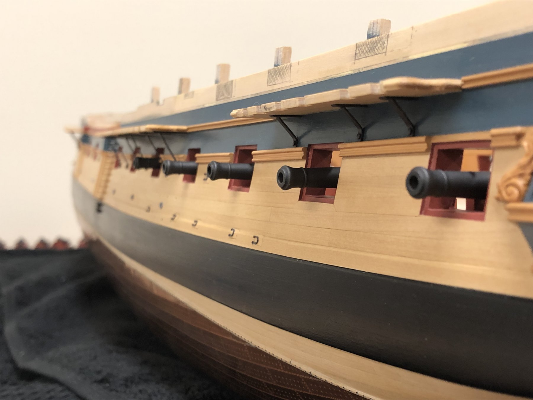
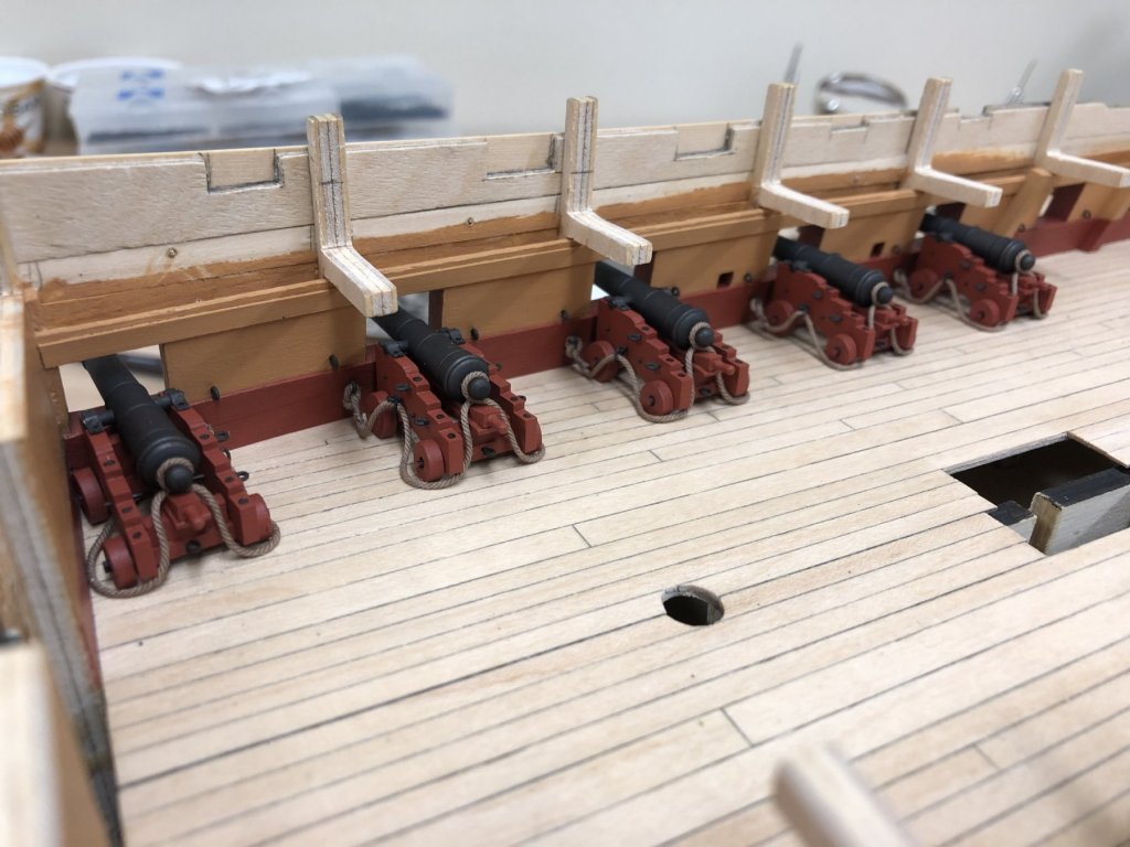
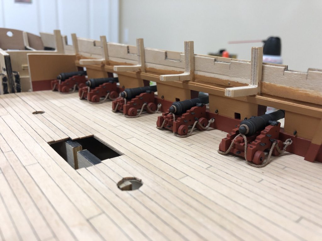
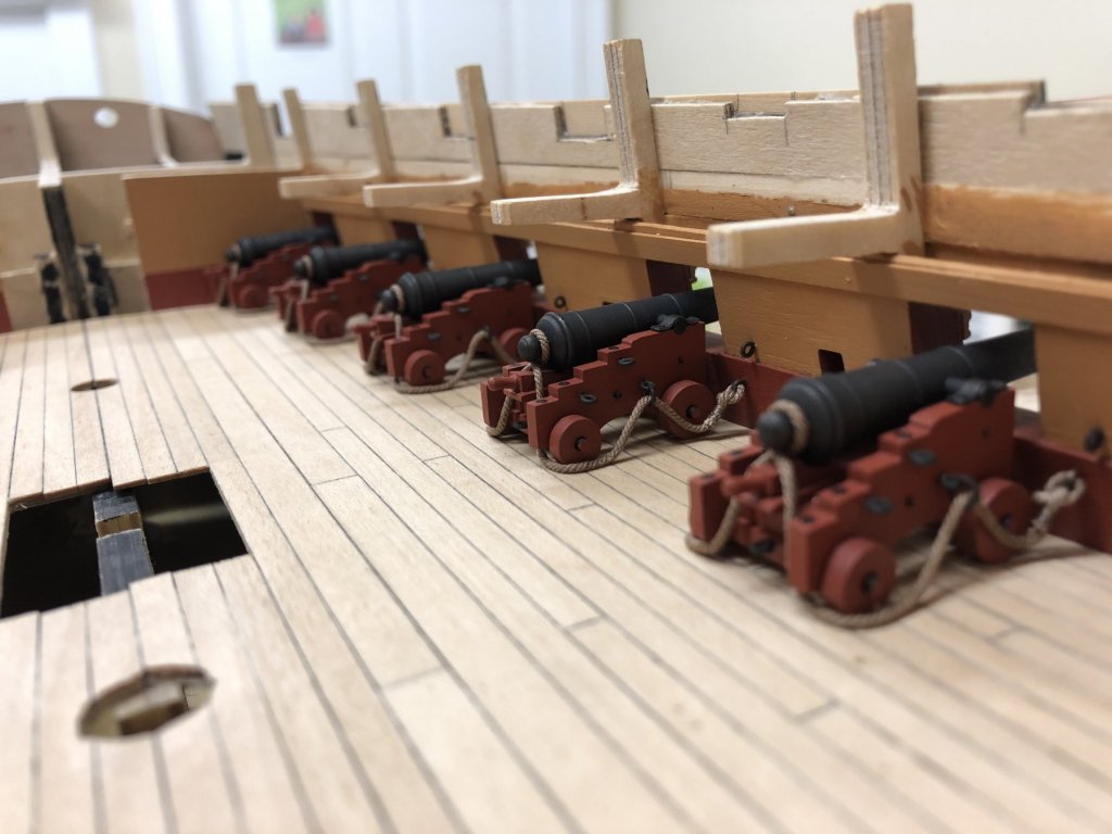
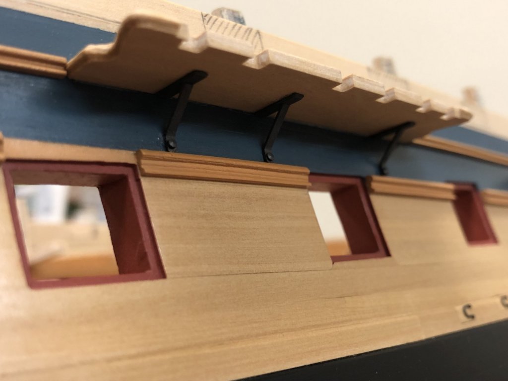
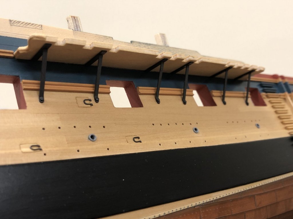
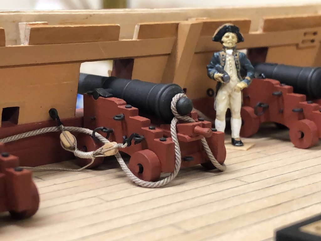
Happy New year to everyone! First off my apologies for not being on the site as much as usual and checking in on everyone's progress, something I hope to rectify soon. My progress has been limited, some small steps have been taken, and problems encountered that stopped me in my tracks for a while. Channel Brackets: The kit supplies PE channel support brackets, unfortunately I found this unworkable as is as the profile impinged on the decorative molding, they're also a little wider than indicated on the plan. The PE parts are scored pretty heavily at the bending points so trying to tweak these was not really an option. The problem also identified by others is that there are not enough provided in the kit (per the AOTS there are 3 shown on the mizzen, 6 for main and 4 for the fore channel) and only 11 provided, so the kit is 2 short. Further analysis suggests its likely 3 short as there are 2 brackets used between ports, and it appears that one is simply hidden behind the stock of the anchor on page 69. I'm going to reflect 5 brackets on the fore channel. Another slight complication is that the mizzen brackets need to be smaller to account for the lower position of the channel in the open rail configuration I'm following. Basically I needed to make my own, and without any really good photos to follow went with my gut. Not having any other suitable materials handy, my eye turned to one of the spare sets of PE from other CC kits I had purchased a while back. Not sure which kit, but a little filing and cutting to length allowed the chains to be workable. These also appear to be almost exactly the same narrower width as shown in the AOTS profiles. The center portion of the Diana PE part was re-purposed to attach to the channel. Exactly the same approach was taken for the mizzen, except that the top of the Diana PE part was used and different dimensions for the bracket supporter. This was all rather fiddly and took rather longer than I'd care to admit... 🙂 Cannons....finally: Once the channel supporters were in place I could then proceed with installation of the cannons. These are now glued in place (using CA), I didn't pin these in place as this would have been a little problematic at this stage, and they seem quite secure as is. Breeching ropes were attached off the ship prior to installation. Another self imposed delay was decision to go with 'light brown' Syren line rather than the 'tan' used previously - this seems to have a tone that blends better with the colour palette. The Syren line is very nice to work with and the usual trick of using dilute PVA was used to fine tune the final profile. For these more obscured cannons, I used a simple eyebolt to secure the breach rope, for the more visible ones in the waist, I want to explore using ringbolt as per practice, but even using a simple eyebolt gives a satisfactory result to my eye at this scale. And finally, the exterior shot...in retrospect I'm happy with the decision to install the channels and brackets first as I'm pretty sure there would have been collateral damage to cannons during installation. 5 down, 23 to go.

-
Wreck of Bonhomme Richard found off Yorkshire coast.
Beef Wellington replied to uss frolick's topic in Nautical/Naval History
Here is the US take from FOX NEWS, I'm sure many will find the inaccuracy of the picture of HMS Serapis somewhat amusing 🙂 (spoiler alert...they pictured the 1866 troopship rather than 1779 5th rate) https://www.msn.com/en-us/video/science/remains-of-us-revolutionary-war-frigate-discovered/vi-BBQOCzj?ocid=spartanntp -
Very nice work, and I admire your attempts to get the keel looking as good as it does. The bulkheads must have been tricky to cut out.
-
Love the last set of photos, really show how well you have subtly highlighted the small details which adds so much interest to the hull. Windows came out really well, how much did you dilute the PVA?
-
Bulkheads have turned out really well despite the challenges and colors compliment very nicely. I keep looking at the pictures and can’t see the gaps you’re referring to.
-
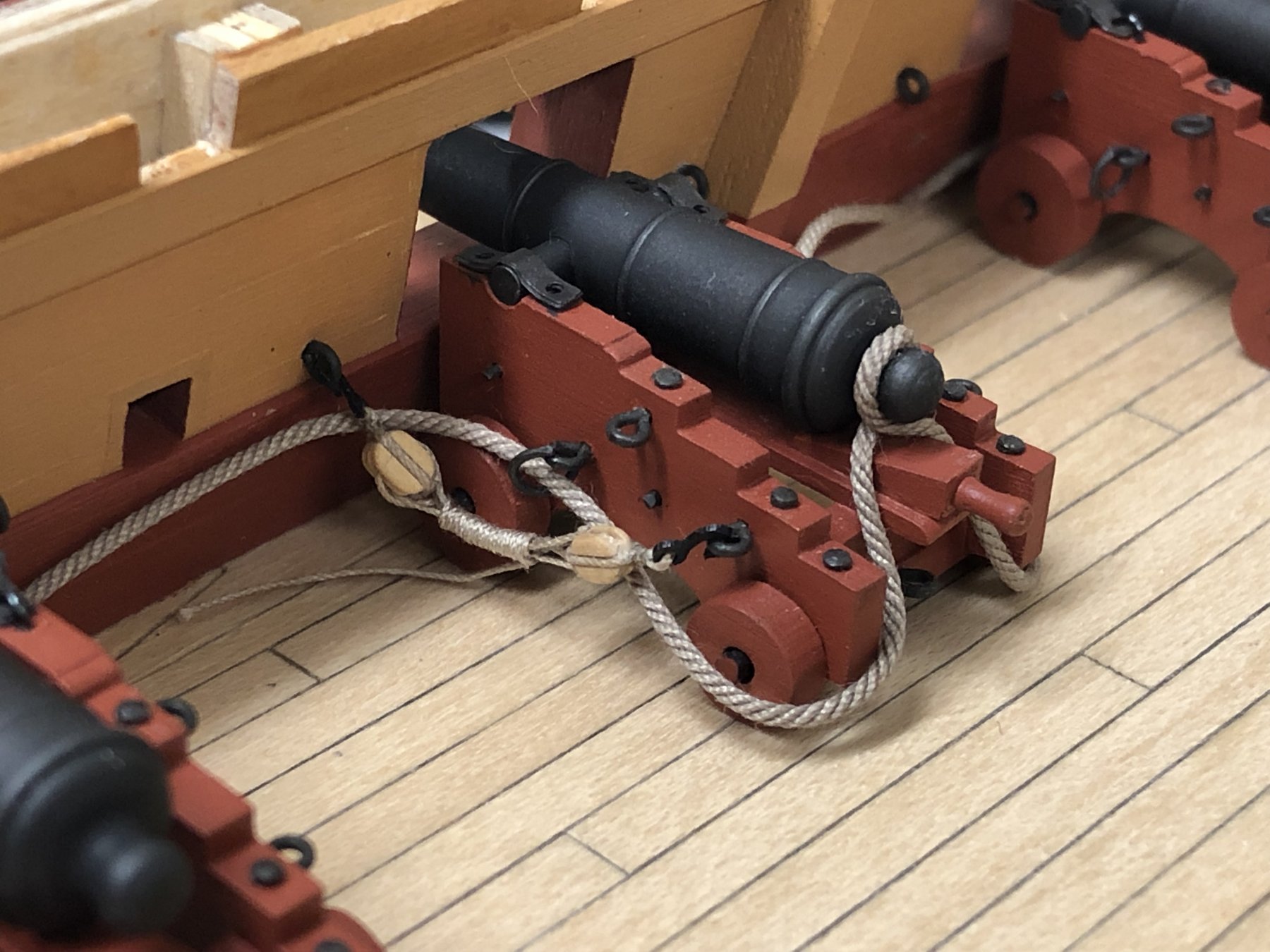
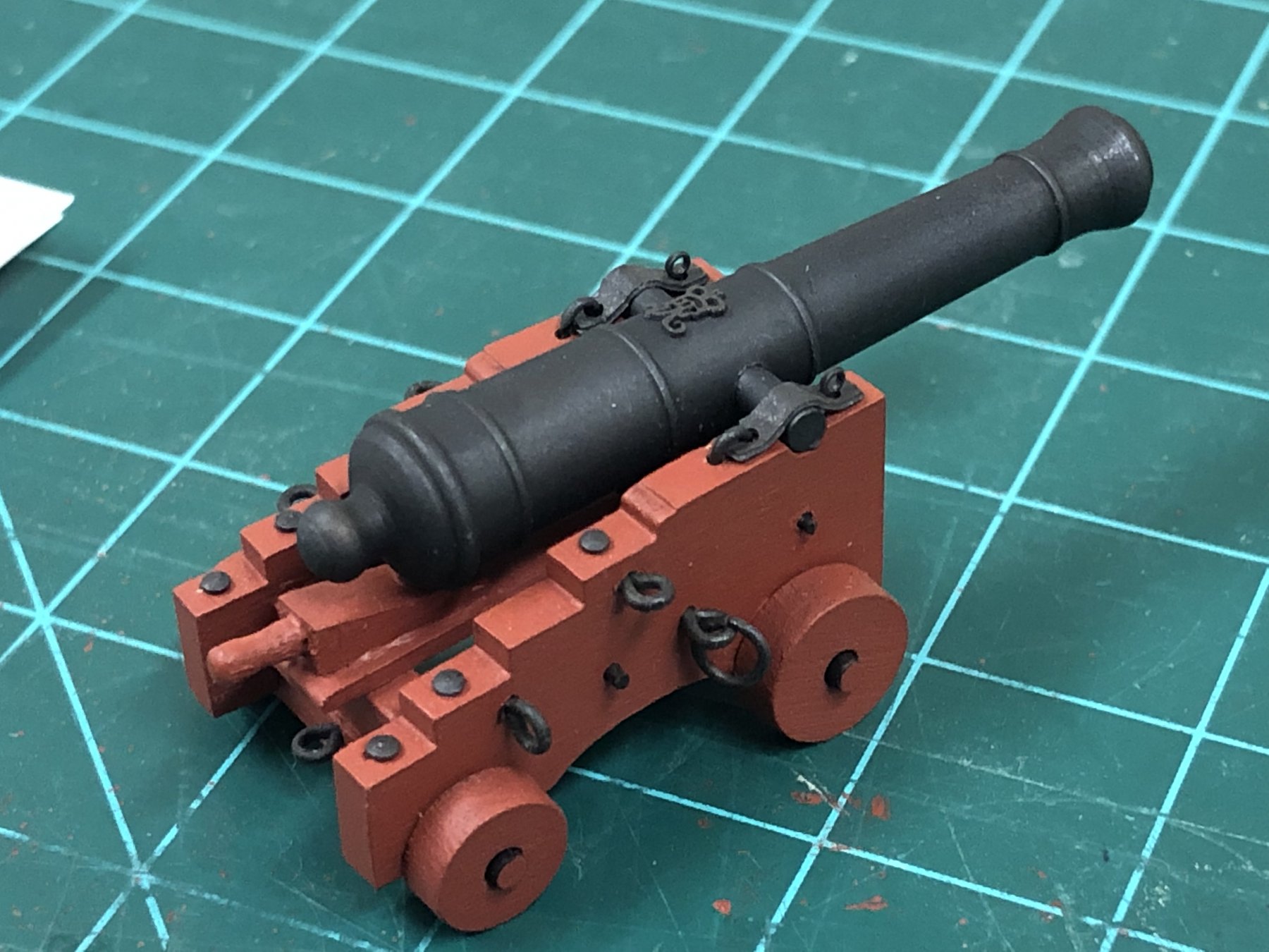
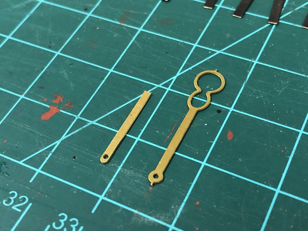
Happy Thanksgiving to all of those in the US! Unfortunately the shipyard has had to suddenly close due to a minor, but messy, health and safety violation involving a clumsy thumb and Xacto knife - nothing serious but plasters/band-aids preventing fine work. Good opportunity to sit back and ponder gun rigging as I'll need to order additional materials from Syren. Think I'm done with additional detailing on the cannons in the interests of sanity; Monograms are from Syren, given a quick dash of 'dark iron' Cpaint and glued into place with CA Cap-square eyebolt made with wire and the cap square joint bolt is one of the smaller PE ring bolts. First mock up of potential rigging, as previously discussed, the breech rope is 0.88mm Syren line. This line does make the half hitch a little more cumbersome, but think it can still work, even though they will be somewhat hidden even for most visible guns in the waist. Going to live without the wheel lynch pin and cap square pin/chain. Cannon rigging: Breeching rope does require some dilute PVA to hold into position on the button. Wanted to give the hauling tackle a feeling of 'weight', and have been experimenting assembling these off the model using a serving machine to get consistent spacing and also do the frapping. Procedure still to be finalised… Details as follows: Block are 1/8" (3.18mm) single/double blocks from Syren Blocks are stropped with 0.012"(0.3mm) line Port tackle line is 0.008" (0.2mm) line Hooks are 4mm from Syren (these are black plastic which I ordered some time ago and don't think Chuck still offers them which is a shame as they seem easy to work with)


-
Very interested to see this 'officially' come together, this is a beautiful ship - of course there can be no complaints about the kit 🙂
- 356 replies
-
- 4
-
-
- red jacket
- finished
- (and 1 more)
-
You really are motoring Ian and she's looking very nice! Would not have noticed the gun port height issue, very cunning fix. Good luck with the roof, also, a very nice clamp collection 🙂
-
Those breeching rings came out really nicely an look just perfect, I'm sure at 1:48 its worth going that extra step to close these. I really need to dive in and learn soldering and metal working techniques, been a little wary to try up to now. Love overall photo with the cut out figure, he enhances the look of the model by being a little more well defined than the ubiquitous "Captain Amati"...
- 574 replies
-
- 2
-
-
- cheerful
- Syren Ship Model Company
- (and 1 more)
-
Glad I have just found your log before you have got too far Valeriy, love this style of model. Making all of the metal parts must be so time consuming and sadly I'm not familiar with the techniques so looking to be educate by you. I can't even imagine the amount of work you have ahead of you...but it will be worth it.
-
Mike - yes, the scuppers are PE from the kit...and yes, I had the same experience as you! The carpet monster also ate a few, and I don't even have carpet! I found the technique of attaching to masking tape, smearing some CA glue on the back side and then positioning, seemed to be enough time to adjust before it fully set. Holes were drilled at an angle to the hull to try and give the impression of the tube angling up to the deck, but that proved a little hit or miss. Closeup, think the PE definitely looks overscale, but from regular viewing distance they blend in OK, and they will probably blend further when the other hull fixtures are added. Well, I asked the question and MSW answered!! Thanks everyone for your input, you've swayed me to the larger size, not a single vote for the smaller dimension. Of course the larger rope will require far more taming but I'll solve that in due course. Now to figure out how to attach to the ringbolt with a scale appropriate solution... Just before putting this to bed, here is a picture I found from Endeavour which shows a smaller size breech rope which initially played into my deliberation.
-
Sadly this bring back many memories....I did the triangle solution, don't recall whether it was even possible to achieve what is illustrate in the plans. Think your approach of working the gun port ply based on the deck position is a very sound approach. If its any consolation, the Diana kit is just as unintuitive/unhelpfull at the stern counter as well, I made up my own template. When I was building Snake which was my first build, these are the challenges I put down to my lack of understanding when in reality the kits have just aged. If it hadn't been for this site, I would never have got past this early stage.