Beef Wellington
-
Posts
2,249 -
Joined
-
Last visited
Content Type
Profiles
Forums
Gallery
Events
Everything posted by Beef Wellington
-
 Looks very nice Peta, well done. I think Greenstone meant to say that the flagpole (or staff) would only be used if sails are NOT rigged. The staff would interfere with the workings of the sail.
 -
Hey Mike, can definitely relate! The CC Diana kit predates the precut strip approach and is exactly what you are dealing with. What I found especially tricky was keeping the sides of the gunport vertical (parallel with hypothetical frames), but the top/sill parallel to the sheer of the deck. Can't tell from your photos whether the rearmost ports are completely square or not from your photos. Anyway, congrats on reaching this stage, looks more like a man o' war now than a bathtub, very satisfying I'm sure.
-
Bob, for what its worth, I'd vote for the thicker thread - purely because it may provides a little contrast to the other stays which will obviously thinner as they go up the mast. Something that I find visually more satisfying for some reason. Looking great BTW, don't beat yourself up over the serving!
- 421 replies
-
- 1
-

-
- caldercraft
- granado
- (and 1 more)
-
Hi Chris, think its definitely worth planking the lower deck, I think the only hatch that will only be slightly visible is the lower fore-hatch, the center one in your layout. I did add this myself, even painting black it takes some craning to glimpse it once the companion ladder is in place. The lower main hatch is totally obscured by the main hatch ladder. Definitely agree with the lighter caulking. Starting to come together now, looks good.
-
Loved catching up on your progress OC, not usually a fan of figurines, but those figures fit right and give a great sense of scale. You really did a great job painting them, and the rigging is looking terrific.
-
Hi Rob, love the last photo's, great to catch up on your progress. She really is looking spectacular, the extra detailing in the tops is well worth the effort. Something I remember reading somewhere (never seem to be able to remember where), was that rigging lines would have been secured to the open rail, the pin rails would only have been needed once the bulwarks were built up. Hopefully someone can confirm. Have been a little distracted myself recently and "Jason" is on a little hiatus right now. Have been struggling with finding some reasonable quality maple strip that does not have horrible flaky edges and/or surface grain...
-
Looks stunning Rob, think you are now about 2yrs ahead of me 🙂 Very interested to see you approach on the head gratings.
-
If you do a quick search on Badger you will find many build logs of this kit to get more information and answer your question. Similarly there are many many build logs of other Caldercraft kits to read through.
-
Nice deck and details Peter, looking great. The balcony looks nicely to scale.
- 366 replies
-
- 3
-
-
- bellerophon
- victory models
- (and 2 more)
-
Looking very good indeed Nils! I was wondering who the giant hand belonged to 🙂 You've really achieved a true scale look, the close ups could be the real thing. I'm sure the clinker painting is a challenge but turned out very well indeed, I'm sure it causes similar challenges at full scale. Oh, and love all the detailing, very much enjoy following along.
-
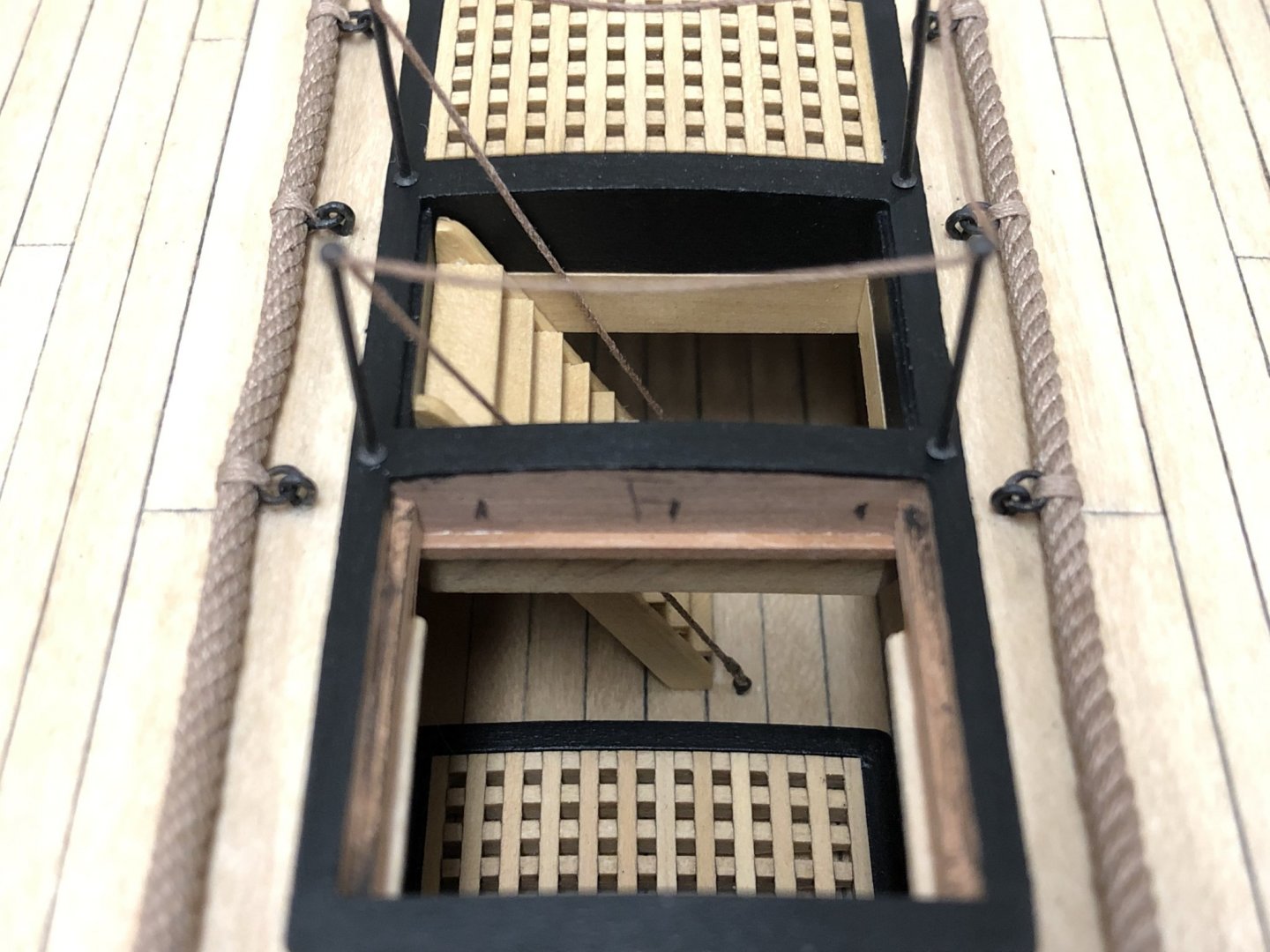
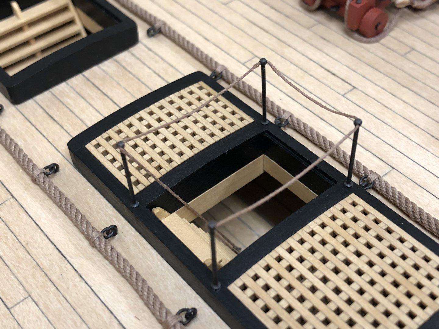
Cheers gents, Small update reflecting this weekend's work. Have been unsure what to do with the fore companion ladder and whether to include the safety lines and whether these would look right, but approaching point where decision is needed. I seem to recall reading in TFFM that the hand ropes would have been secured to small ringbolts in the deck below (there really should be a word for the situation where you remember reading something but then are subsequently unable to find the reference when actually needed!). Small PE ring bolts were used in the lower deck and 0.3mm line secured to them with a false splice. RB Models stanchions were used as they seemed a little more to scale, rather than the kit supplied items which appeared too tall - these may not be completely period accurate, but are close enough to my eye. I feel there should also be something around the main hatch companion ladder, but cant quite see what this would look like, as the iron supports for the pumps are obstructions. The only way I could figure out to install these was to estimate the length of line needed and then attach the ringbolts off the model to - I was anticipating many redoes here but luckily seemed to get it how I was hoping on the first attempt. The location of the ringbolts was determined by dry fitting the companion ladder, the ladder only being finally installed once the hand ropes were all in position.


-
That's a really nice job on the planking. Don't think you need to obsess over wood filler, I seem to remember using a walnut coloured filler that blended in quite nicely (even though I painted over it!) - think because there is so much colour difference with the actual wood it tends to blend in. For smaller gaps, a technique that works well is to put PVA in the gap, you can then rub in walnut sanding dust or once the PVA has set a little, sand over the surface and the wood dust will set in the PVA. This is surprisingly easy and effective, used this quite a bit on my current build. For the bulwark bulkheads, think many people use some sort of saw to help get these off, twisting never quite seems safe!
-
Gents, very much appreciate the information being shared. Could I please suggest that any further discussion on gun rigging and cannon firing techniques and procedures find their way into a specific post for that purpose, there are already quite a few of these already on the site and definitely better placed there to keep all content relevant and on topic. Of course more than happy to answer questions on the approach taken for this model.
-
From what I've seen, the edge would be rounded off, but to varying degrees. The more tapered at the top of the stem, the more rounded the profile. Nearer the keel the profile would be more square as it transitions to the width of the keel.
-
Vane - My preference is always to look to evidence where possible for inspiration. "The Sailing Frigate" by Robert Gardiner is an illustrated book charting the history of the frigate using contemporary models...I take no credit for anything! The following images are from the National Maritime Museum collections site, but are illustrated in book mentioned. Minerva (1780) showing the yellow ochre bulwarks with red spirketting https://collections.rmg.co.uk/collections/objects/66278.html Winchelsea (1772) showing the black coamings https://collections.rmg.co.uk/collections/objects/66277.html
-
Cheers Mark, OC for kind words and the likes, appreciate the ongoing interest. @Pat - he does sup while working 🙂 @Bob - Welcome aboard! My main source for this is The Fully Framed Model by David Anscherl (in this case Vol II, page 145), an excellent and very digestibly reference pulling together information only otherwise available in primary sources. As Phil points out above, line would be looped around the tackle blocks a couple of times first, and this is a slightly simplified representation, as pointed out, this can be seen on HMS Victory in practice. I think a lot of modelling decisions are based on aesthetics, and my personal preference is for a nice clear deck. Practically, guessing this would have kept the line off of an exposed deck which would likely have resulted in rot issues over extended periods of time. @Phil - I appreciate the interest and kind words. The blocks are 1/8" single and double, and the paint used is Admiralty Red Ochre supplied by Caldercraft. The fine thread is UNI-Thread W 6/0 Tan - not sure what that means, but that's what's on the reel! Nothing fancy, think I picked it up at a local craft store some time ago, its synthetic so need to use GS-Hypo cement rather than PVA if it needs to be secured. @Vane - I'm embarrassed to say it, photos are from an iPhone.... 🤐
-
I'm not sure there is an absolutely correct answer to this question, I wondered myself many times, and I'm sure varied according to period, trends and fashions. I do enjoy looking at the many examples of contemporary models, but these typically do not tend to show model with cannon, but where they do they appear to be both red carriages and wheels in the 18 century/Royal Navy category. Who knows, this may also have been modelers whimsy, my own choice was to go with red wheels, but that was simply because I felt that anything else would have just looked too busy within the context of the model. Nice thing (or not so nice depending on your preference) is that leaving unpainted allows you to show some other details like the bolts in the wheels (Blue Ensign has a really good example of this in his wonderful Pegasus build) There are 3 current physical examples on historical RN ships (Victory, Tricomalee and Unicorn), and the USS Constitution. I don't think any of these could be considered to be contemporaneous: HMS Victory - yellow ochre carriages, wooden wheels Trincomalee (slightly later period) - red carriages, black wheels Frigate Unicorn - unpainted carriages and wheels, these are relatively recent additions to the ship to make it a more interesting visitor attraction and I'm not sure how much thought was put into period accuracy USS Constitution - red (more salmon pink) carriages and black wheels - this is probably the least contemporaneous as the ship reflects her state after later rebuilds.
-
I very much appreciate everyone's input on this. Here is where I landed in terms of representing on a model (see photo approx. 1/2 way down in post below), photos show things way better than I could describe, so would welcome any thoughts or comments on the arrangement as modelled as its not too late for me tweak. Models of course don't have to conform to the rules of practicality, and seek to perhaps be more visually appealing, but its still nice to give a nod to actual practice.
-
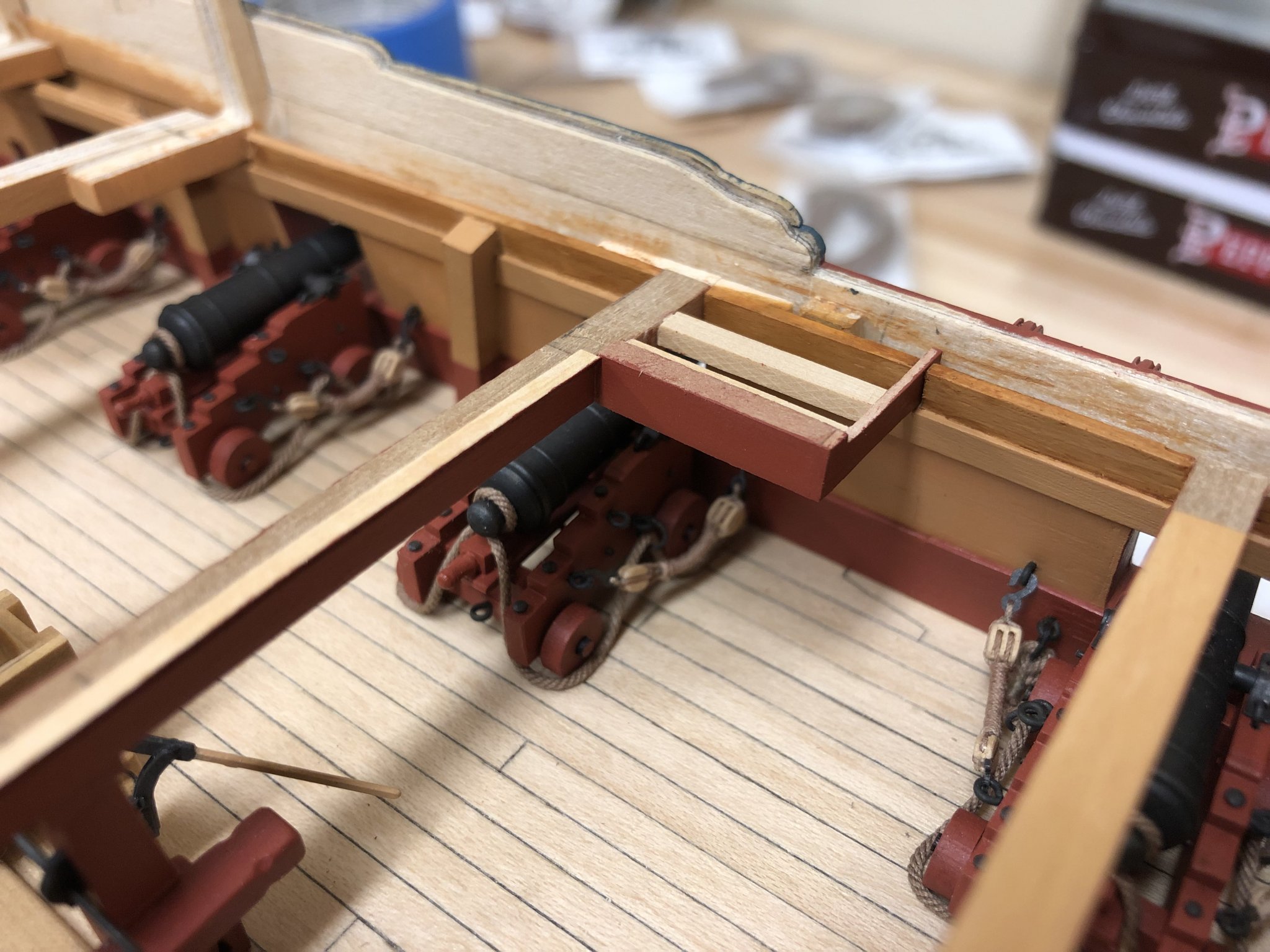
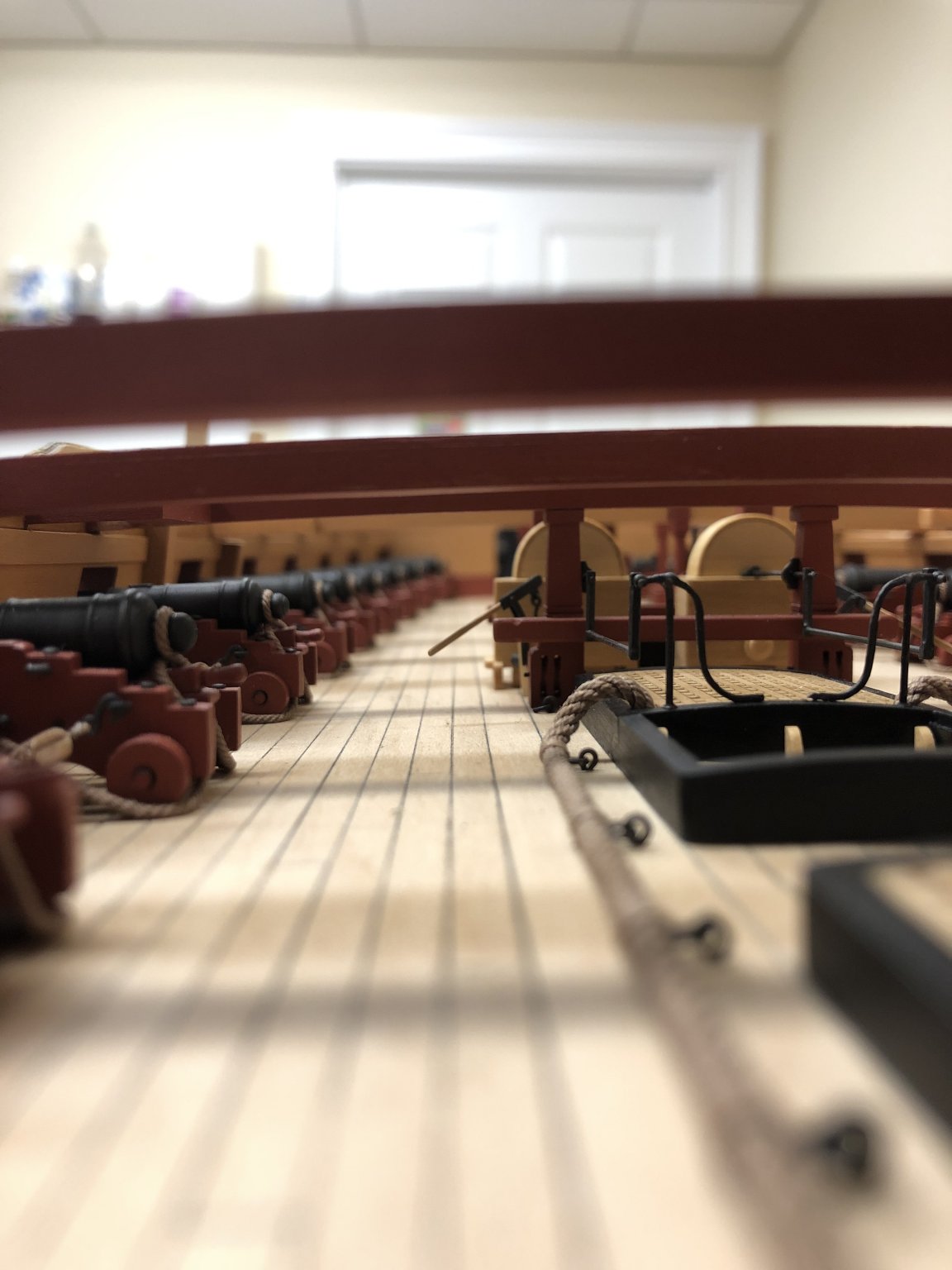
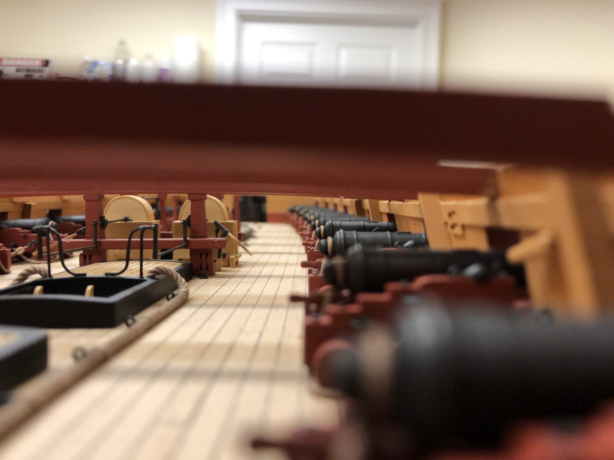
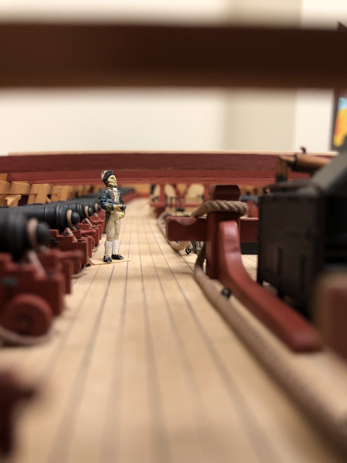
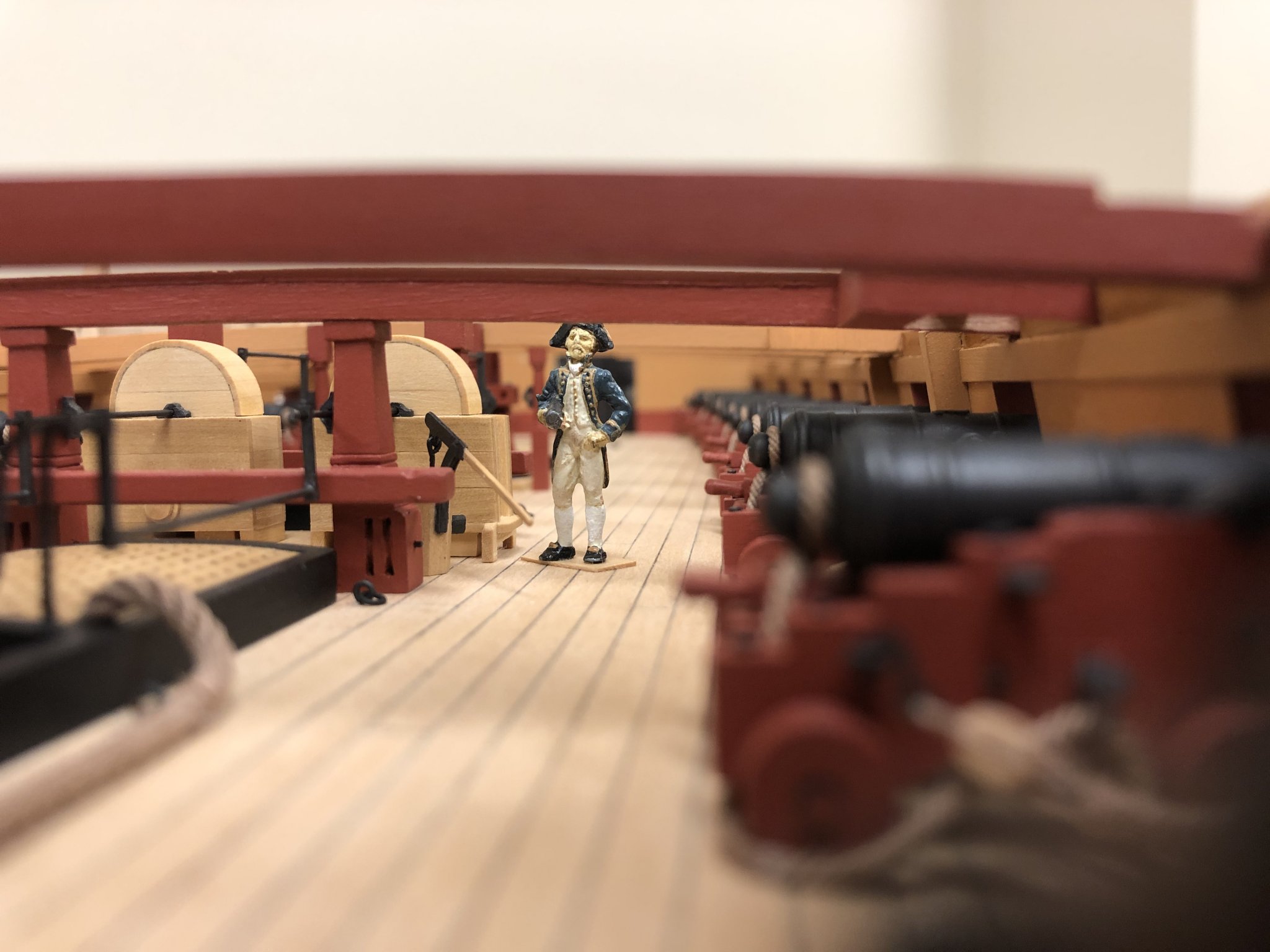
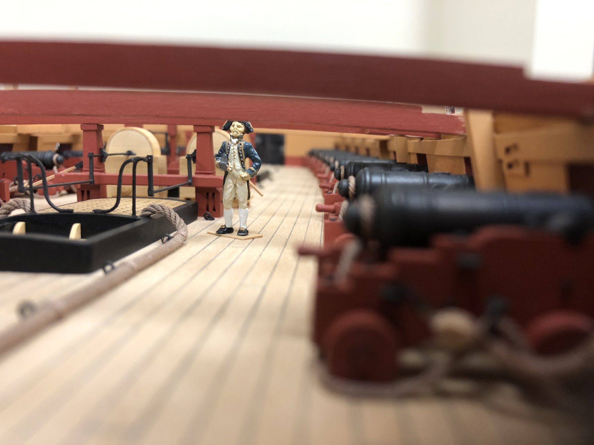
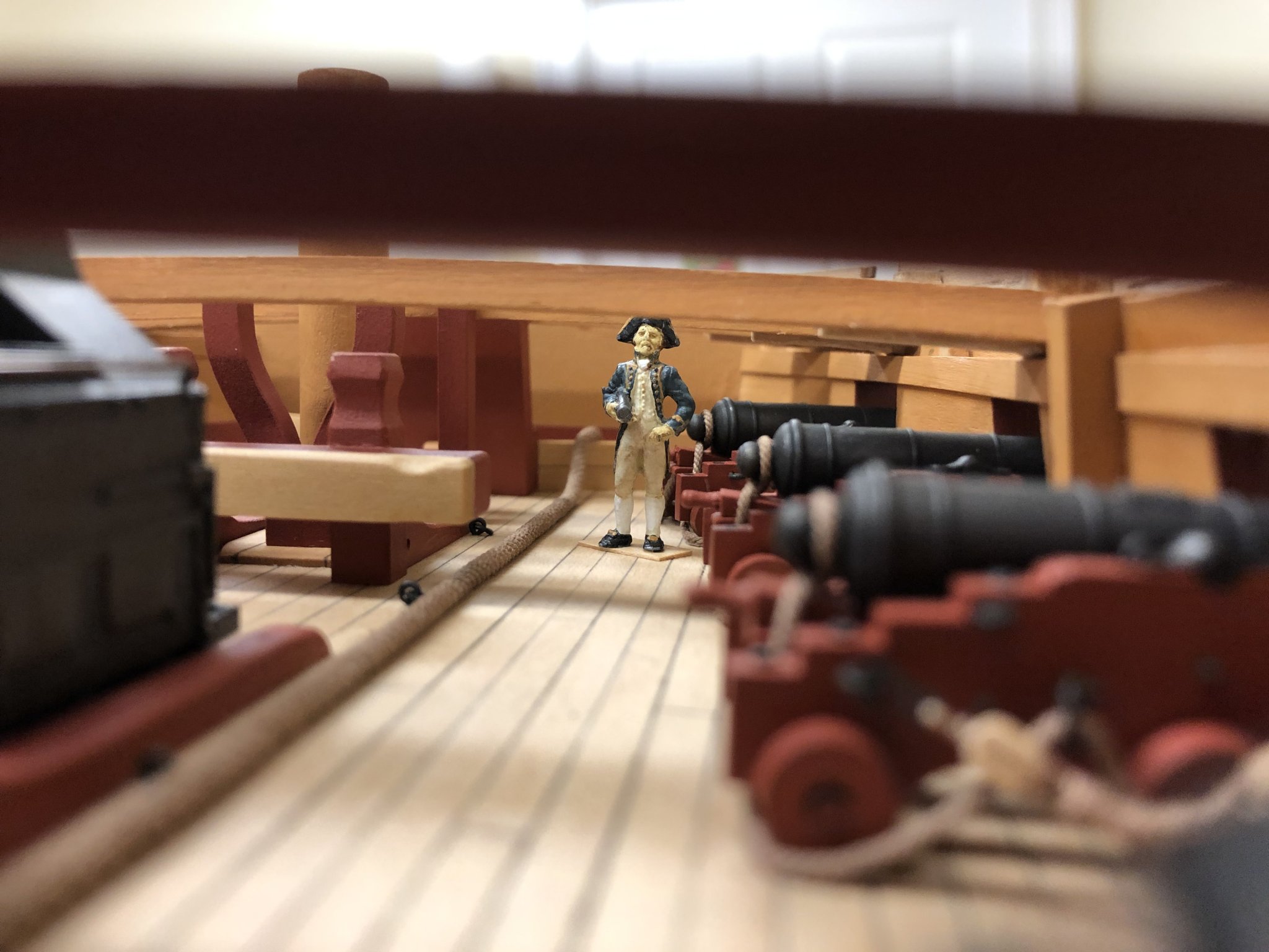
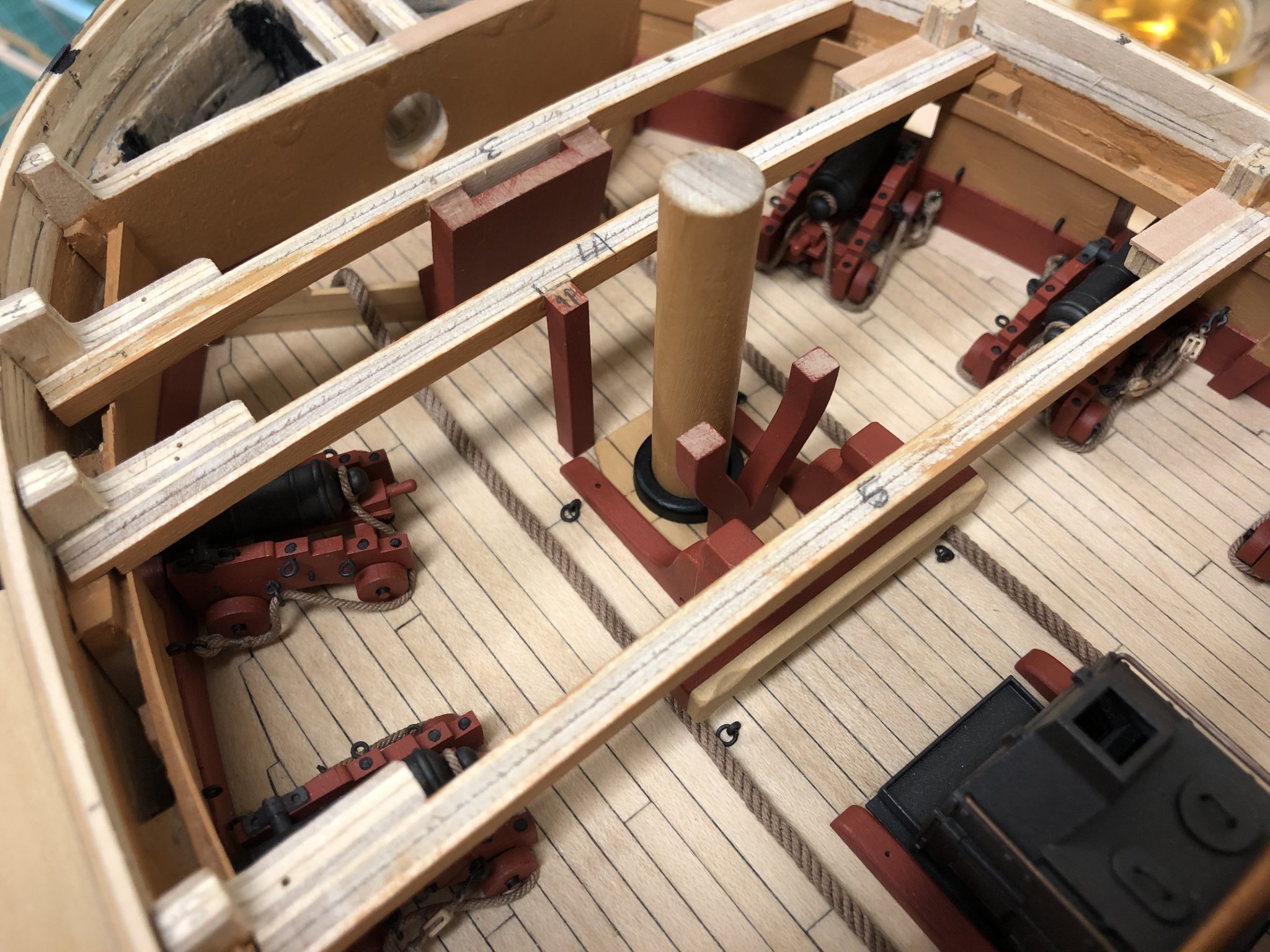
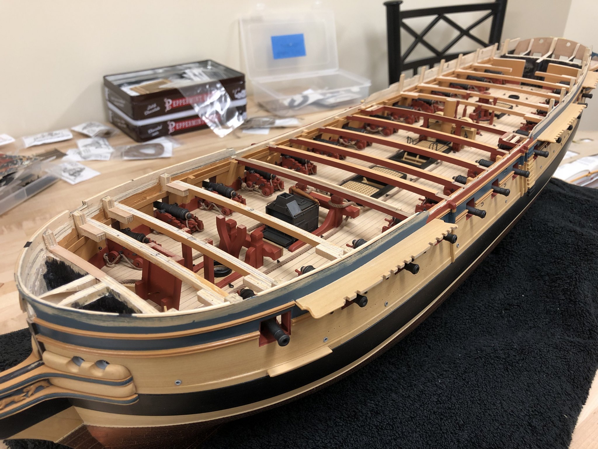
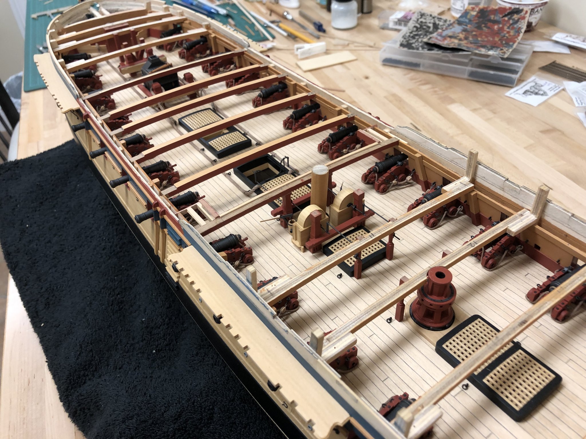
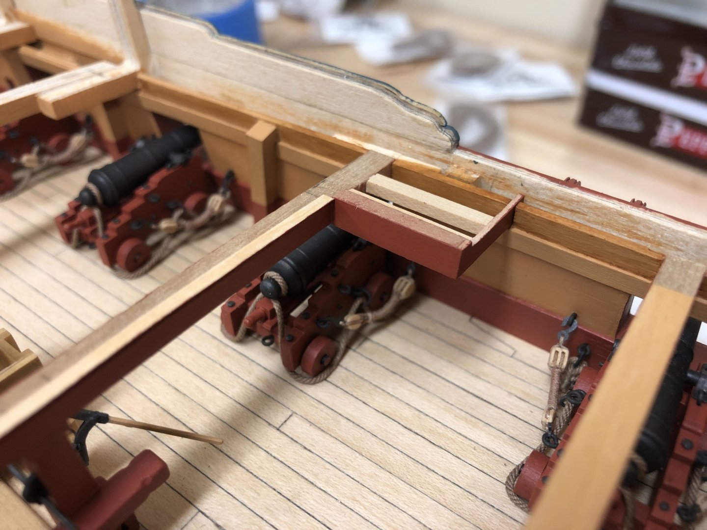
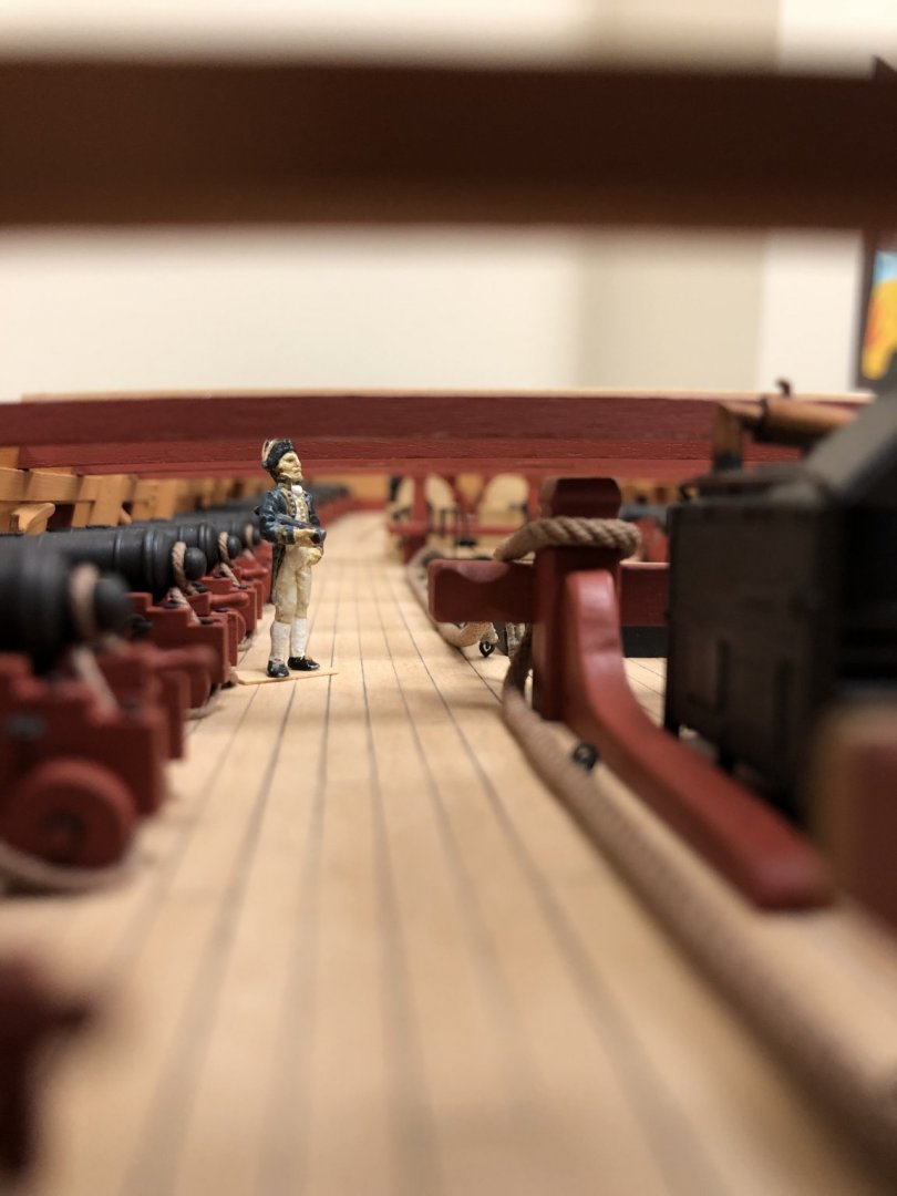
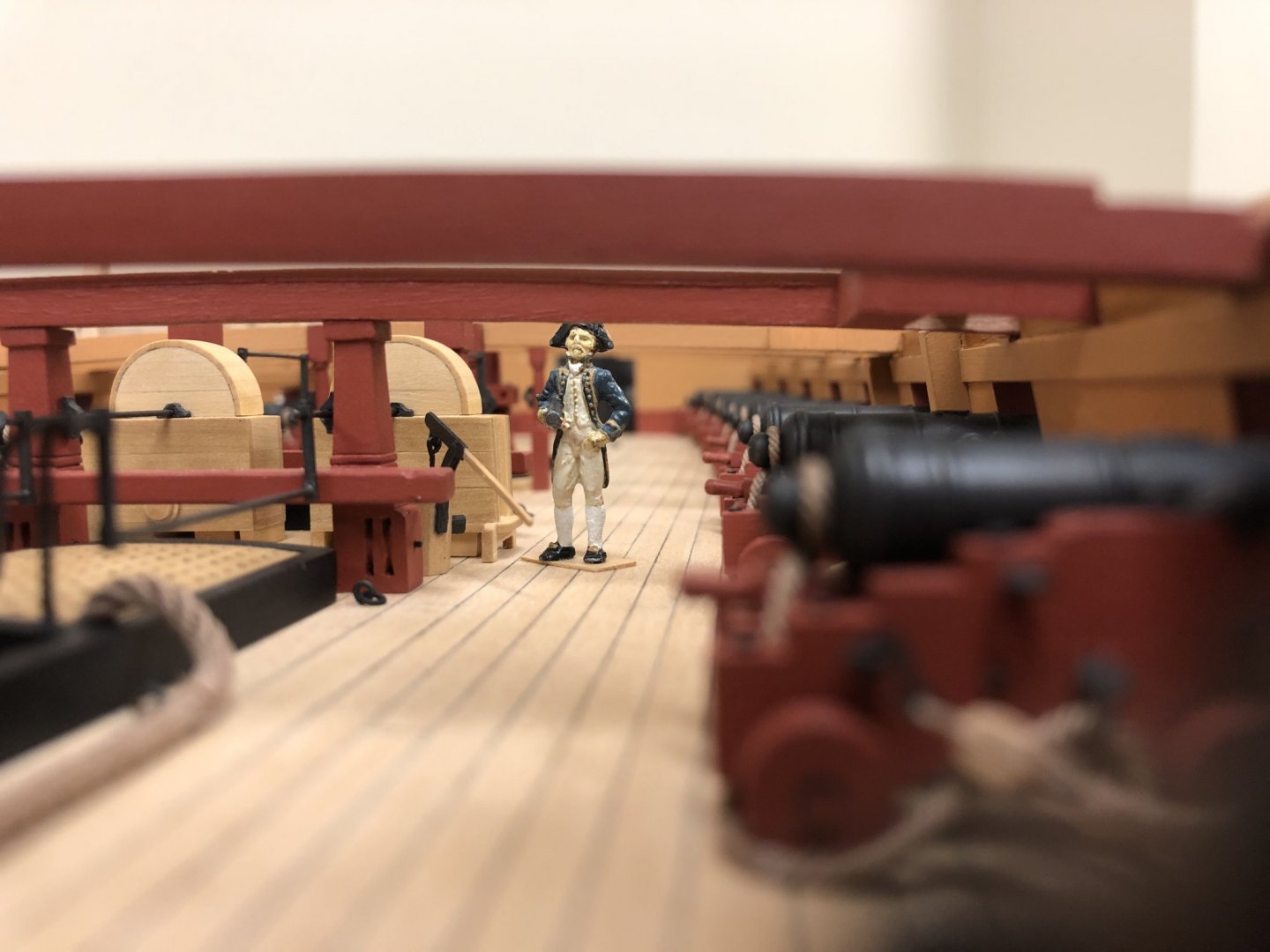
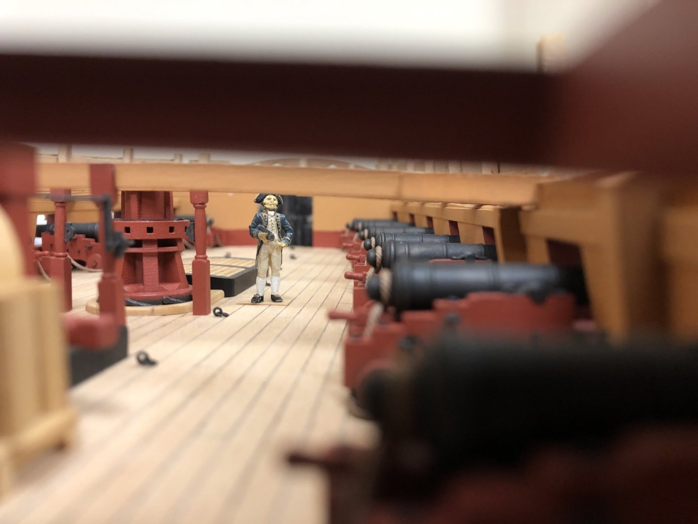
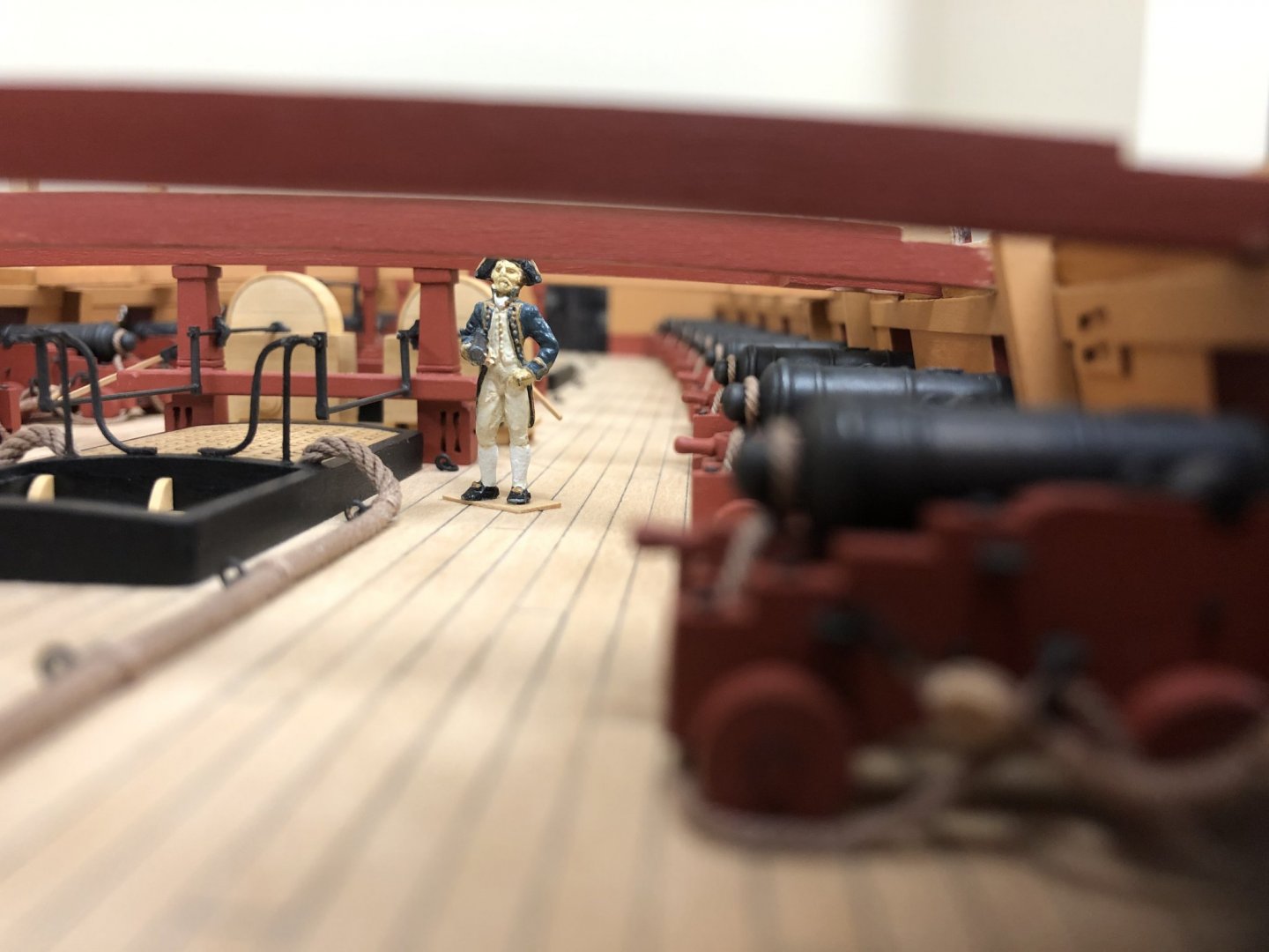
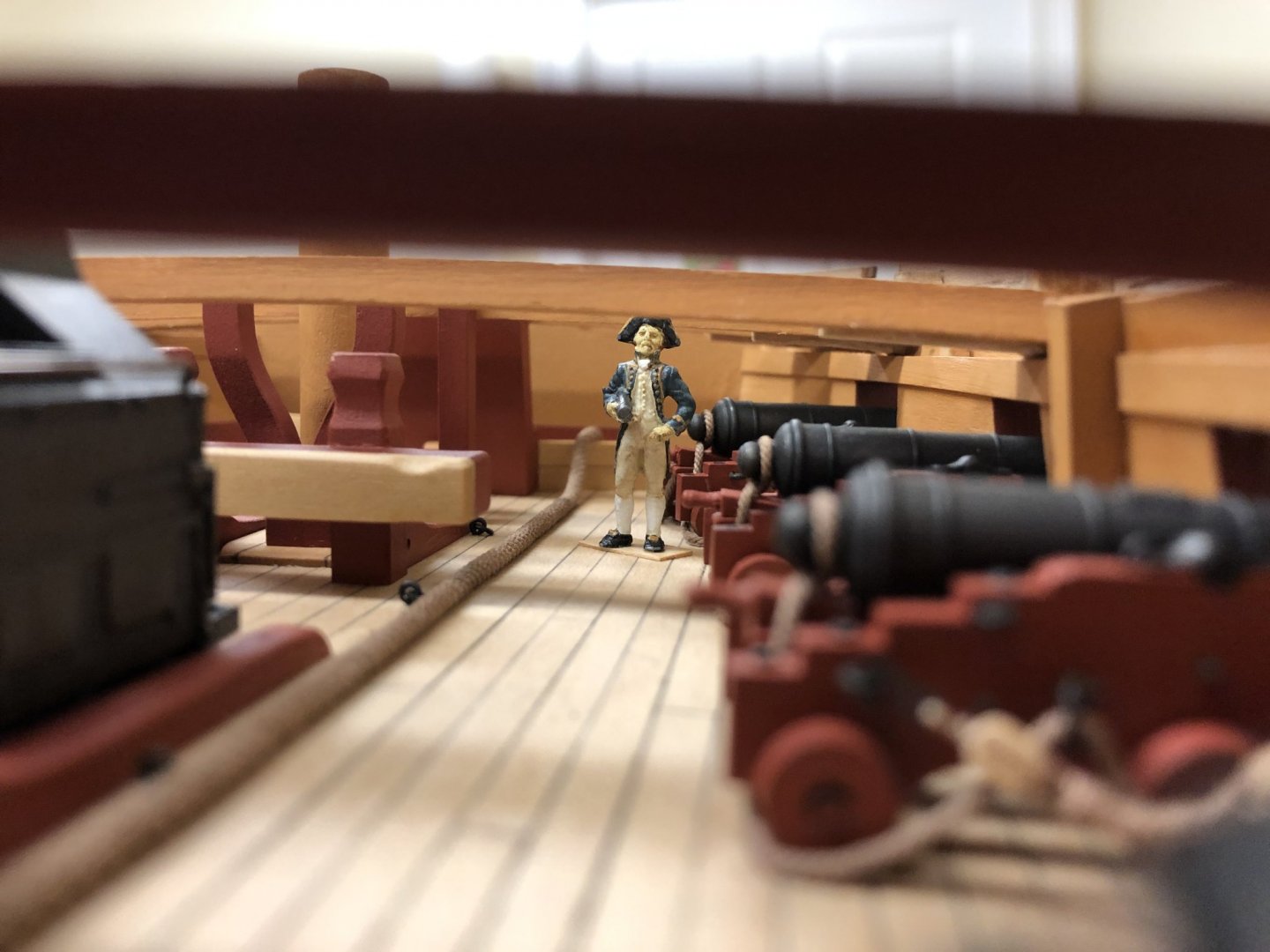
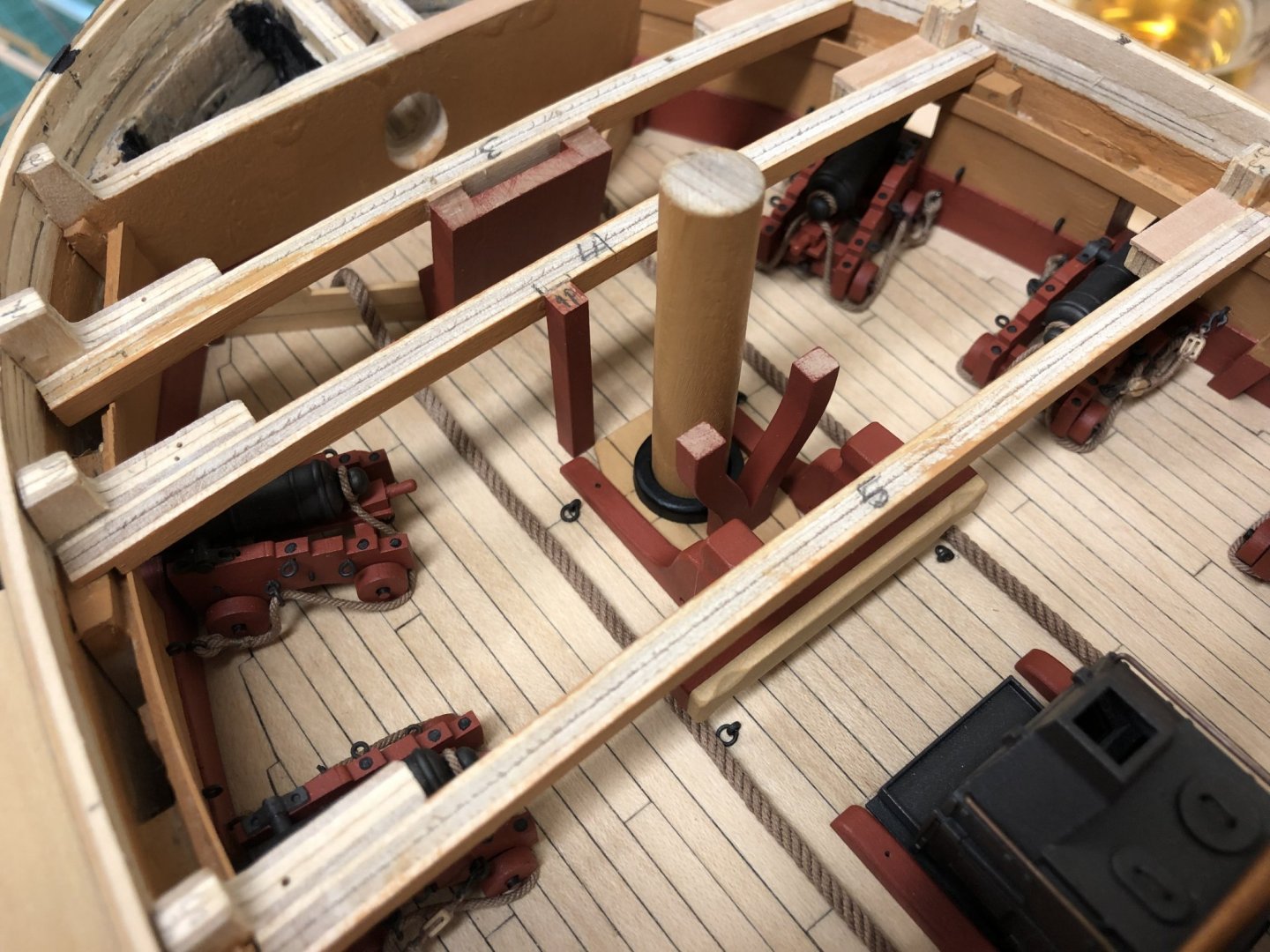
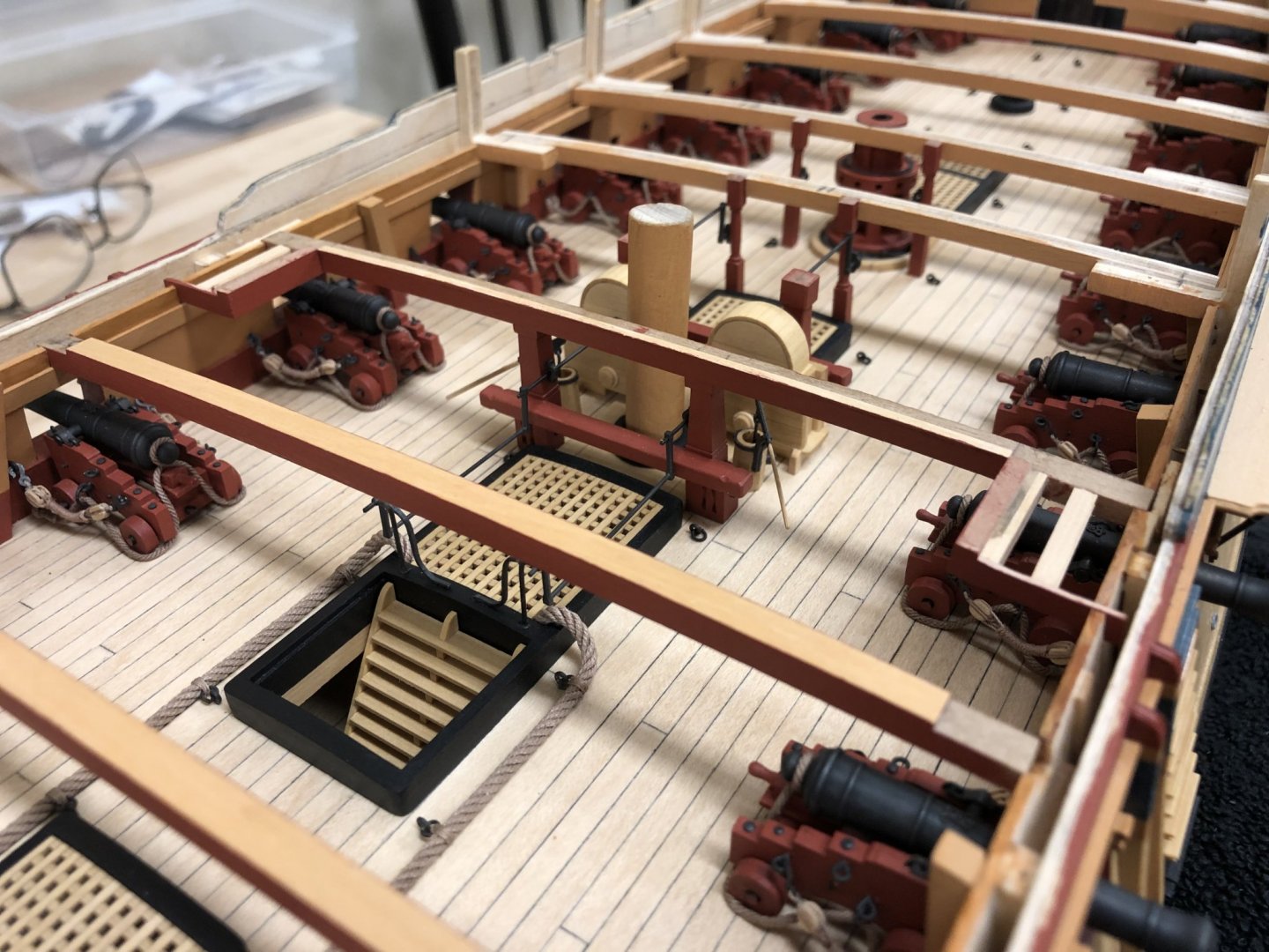
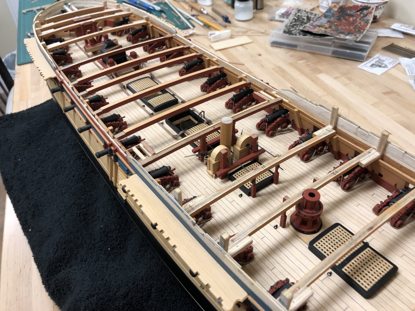
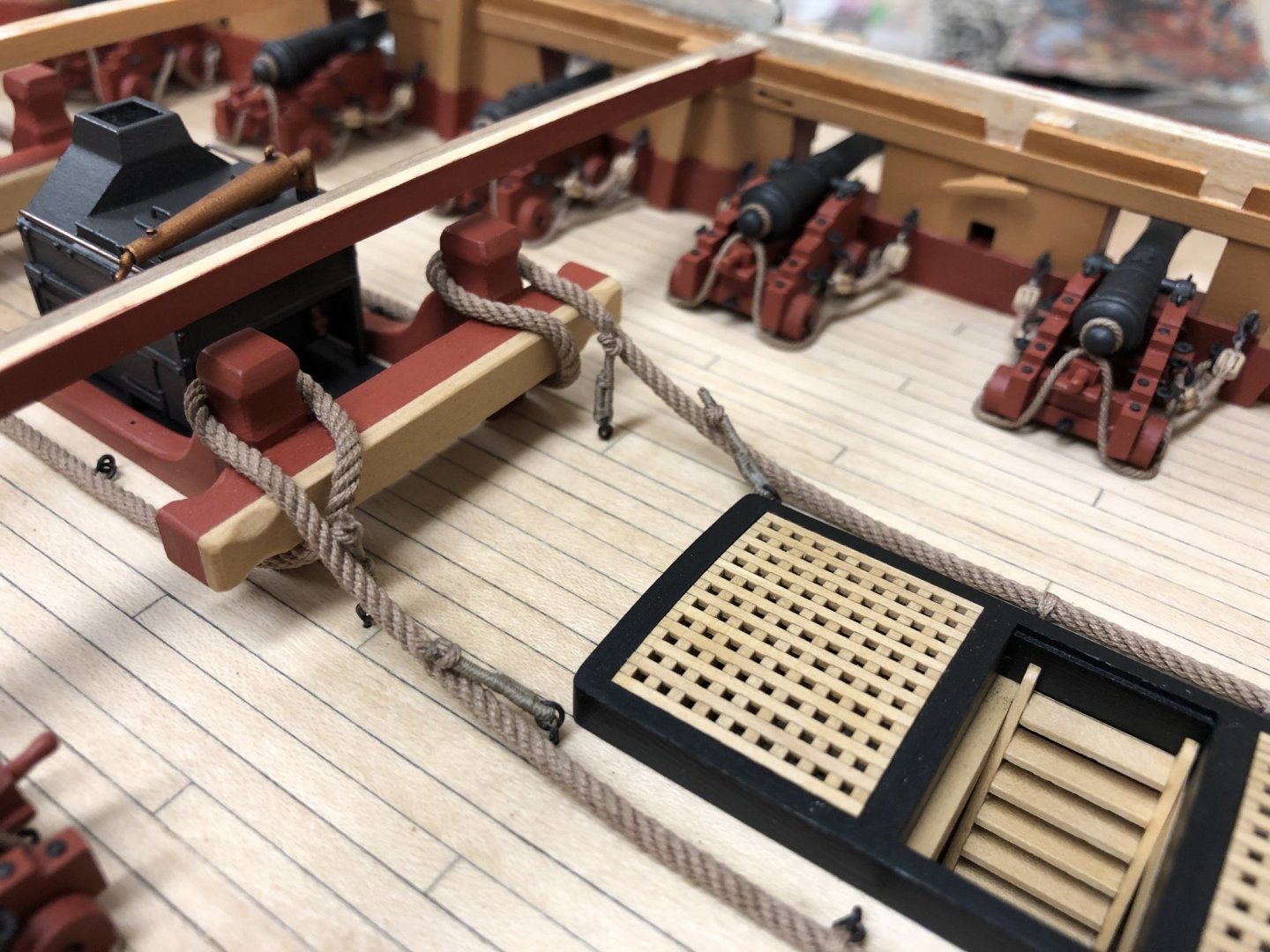
Many thanks all for the comments and likes, definitely good to have people along for the journey.. Feels like a chapter is coming to a close, finally seem to be closing in on completing the upper deck. Definitely a multitude of time consuming small tasks. First off I needed to address the fixed part of the gangway. This is shown quite clearly in plan view on page 46 of AOTS Diana, however it is not shown in profile. Given that it appears to contain its own lodging knee, I decided to extend the profile of the deck beam. This seems to make sense when recognizing that a ladder will eventually be located here. This highlights one of the inconsistencies in the AOTS book, many diagrams show the non-flush gangboards which I understand were going out of fashion at this point to be replaced by flush gangboards. Hoping I'm not too far off the mark here. A strip with a slight profile was added also to the deck beam to sit flush with the false quarterdeck. The base plate to the stove was ripped off and replaced despite my intentions to leave as, hopefully this sits a little more harmoniously. Cables have been added and "secured" to the various ring bolts beside the midship gratings. AOTS describes these as being used for stoppers, but decided to secure with simpler ring ropes as described in Lever. Stoppers have been modelled as per Lever on the 2 foremost ring bolts, but not yet tied on or attached permanently to allow me to finally decide (or others to refute) the approach taken. Even though this area will only ever be glimpsed, time was spent fully building out the area around the foremast with the For jeer and for topsail sheet bitts as they would appear. The actual bitts on the fo'c'sl will be mounted to the deck, seemed unnecessarily complicated to build these fully. Couldn't quite figure out what was represented on diagrams for the fore jeer bitts until I saw interior photos of contemporary models in the Roger's Dockyard Model collection - but still no clue what the "swan neck" arrangement is called. What is very interesting is how crowded this forward area really is, fighting these guns must have been a real challenge. Warning: Here follows some highly indulgent closeups taken on Captain's rounds! This is the closest I guess I'll get to seeing what this looked like in practice And finally...some overall shots with where things stand..


-
I'm pretty sure that copper plates would look exactly like the photo when first mounted (although I do agree these seem to perhaps be a little more slapdash, but who knows). The copper sheets are simply too thin to mechanically maintain a flat profile when a nail is driven through. Simple water pressure and forces when afloat would very quickly flatten the plates to be absolutely flush with the hull given coppers great malleability.
-
Name plates on 18th century ships?
Beef Wellington replied to mic-art's topic in Nautical/Naval History
Mark - I'm curious where this came from, any insight would be greatly appreciated. Even modern warships have name plaques and clearly identifiable pennant numbers, and this in an era of hyper security consciousness when this would be of more use. Names seem to be so much a part of the ship visual in this era it seems odd that it was only in existence for a period of 10 years or so...probably perpetuated by Victory still having her name on her -
Nice job on the carvings Michael. The colour of the cherry looks vey nice indeed.
- 221 replies
-
- 1
-
-
- queen anne barge
- Syren Ship Model Company
- (and 1 more)
-
Love the detail that you have on the inner bulwark Paul.
-
Great progress Rob, must be a great feeling to have reached this point.
-
Ian, from my experience, getting sufficient tension in rope at this scale is pretty tough as it will put a lot (likely too much) strain on the mounting points - at small scales the relative force of the thread is much more than at full scale . I suggest the following, before attaching the crowsfeet, soak them in dilute PVA while under tension, that way when dry they will retain their taught profile without actually requiring much in the way of tension from the fore stay preventer. You should then be able re-attach avoiding the bow that you see . You could also use the dilute PVA on the standing rigging to introduce a more lifelike 'sag' but that's down to personal taste.