Beef Wellington
-
Posts
2,249 -
Joined
-
Last visited
Content Type
Profiles
Forums
Gallery
Events
Everything posted by Beef Wellington
-
 Ok, could be wrong here so please don't send me to detention...I think war is from the root 'bellum', whereas beauty is from the root 'bellus', so of course in natural latin fashion these conjugate similarly depending on the sex and context.
 -
Rob you're really motoring, love those deck shots highlighting your very fine work. Didn't know Vanguard offered those minikits - I'm now very intrigued. I see that you've also started the ships boats, if you'd be willing I'd love to see how you're approaching those as these seem to be quite the challenge (although Ray managed very nicely in his build). I hope Chris starts to make some 1:64 boats available as minikits as they would certainly be ahead of the dated kit provided items. I've started building the 24' cutter but to hopefully place on my Snake build, and look to be at a very similar place to you, hopefully I can post some pictures later.
-
You look to be off to a really nice clean start Stone, good choice of first build. As you and others have found, the instructions are somewhat dated, so definitely don't feel constrained by them. The gunport pattern is a common cause of concern, but is surprisingly strong. Definitely put some PVA glue on the lower edge to get a good join with the top plank of the first planking as a safety measure. Look forward to following along, and feel free to ask questions. I'm intrigued to see how a 32lb'er fits, I know I played with an 18lb'er from Jason next to 9lb'er chase guns I used and it looked HUGE!
- 5 replies
-
- 3
-

-
- snake
- caldercraft
- (and 1 more)
-
Mark, unfortunately can't help with the shape of the spear question, but its probably fair to say that the 'roman spear' is probably not it, a 'pilum' was designed to be thrown only once into an enemy shield and designed to deliberately break/bend and then be very difficult to remove so the cumbersome shaft made the enemy shield much less effective or impossible to use.
-
Think its safe to say there would have been (or at least expected to be) arms, we seem to have become very familiar with classical statuary without arms but its only because they broke off at some point.
-
Bob, looking great. I think we've both been struggling with the same area and similar challenges but you look to have overcome everything well.
-
Looks great Michael, beautiful!
- 221 replies
-
- 1
-
-
- queen anne barge
- Syren Ship Model Company
- (and 1 more)
-
Very impressive Siggi, can fully appreciate the huge amount of time you've invested to get these to this point, such quality work.
-
Really jealous of your rope there buddy, looks so nice - you've got some really nice detail there, and especially the serving...top notch. Assuming the stay will finally go over the hound of the mast and not rest on the stropping of the block(?) Think I'm over here checking out your progress while you're over at mine... 🙂
- 1,039 replies
-
- 2
-
-
- ballahoo
- caldercraft
- (and 2 more)
-
Hi Peter - I'll send you a PM with the instructions and hopefully all will be clear (but NOT unfiddly!) Short version, the washer with the stalk is glued into the hole on the bottom of the carronade barrel. When mounted, this is then sandwiched between the joint chocks with the other washers with wire holding everything together. In your photo above, you need to reverse the elevation screw, as the wide part needs to be at the bottom. Hope this helps.
-
Great to see you start this, nice choice in subject matter.
- 195 replies
-
- 3
-
-
- lady eleanor
- vanguard models
- (and 1 more)
-
Hi Peter - in my 'Snake' build I decided to upgrade the carronades to the brass Caldercraft version as they were so much nicer, but certainly not cheap - and not much easier to construct. I didn't blow the dust off my Diana instruction manual, but from memory, you will need to drill out the hole underneath the carronade. This then aligns with the two white metal supports (joint chocks?) inserted into the slots in the carriage, and piece of thicker wire then inserted in the hole and cut to length. The elevation 'screw' (saying that loosely as they seem bent or broken) then sits in the small hole at the rear of the carriage which stabilized some more. If that doesn't help, I can try to draw a picture later when I have some time.
-
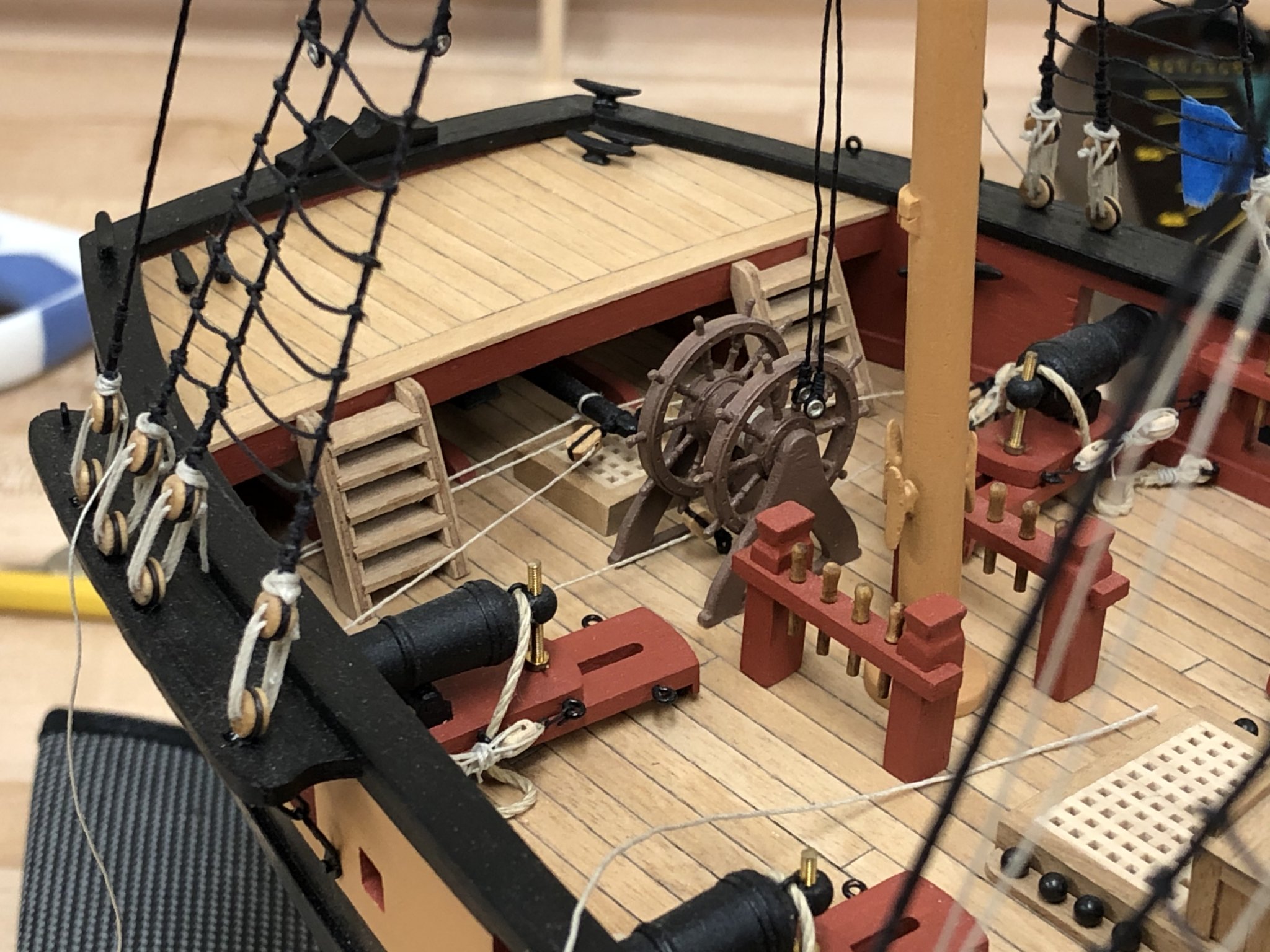
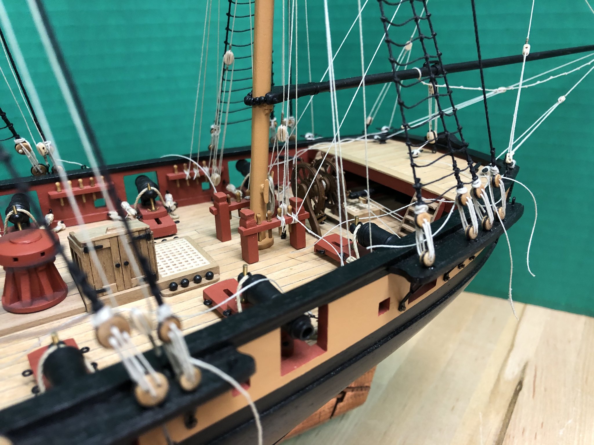
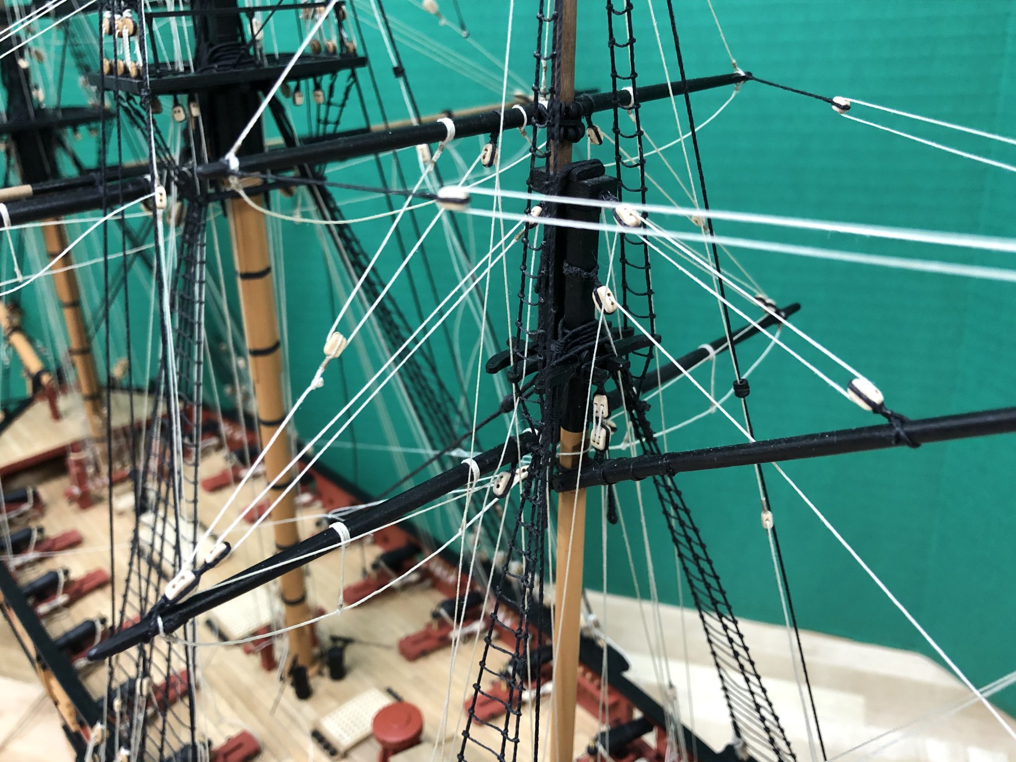
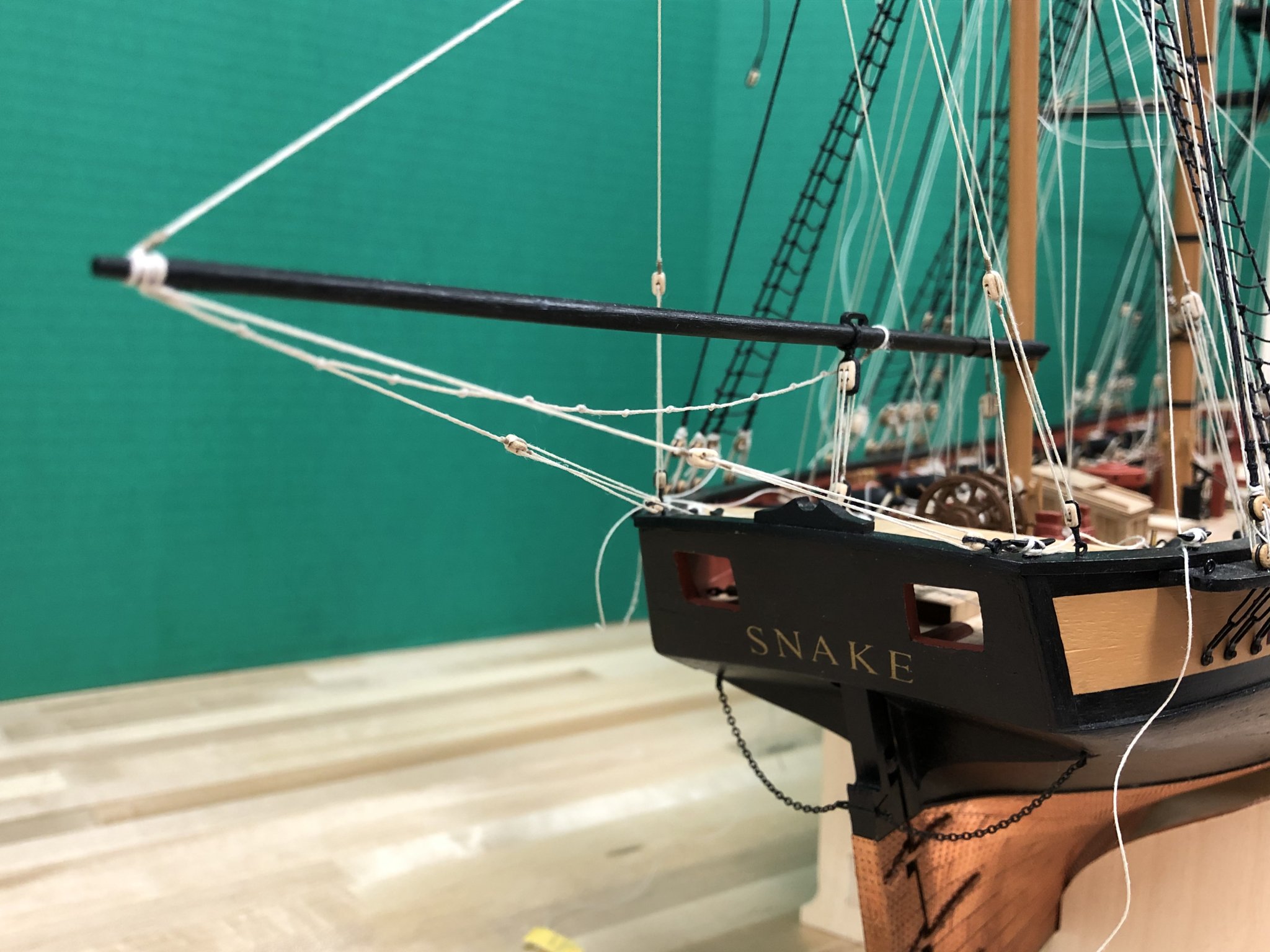
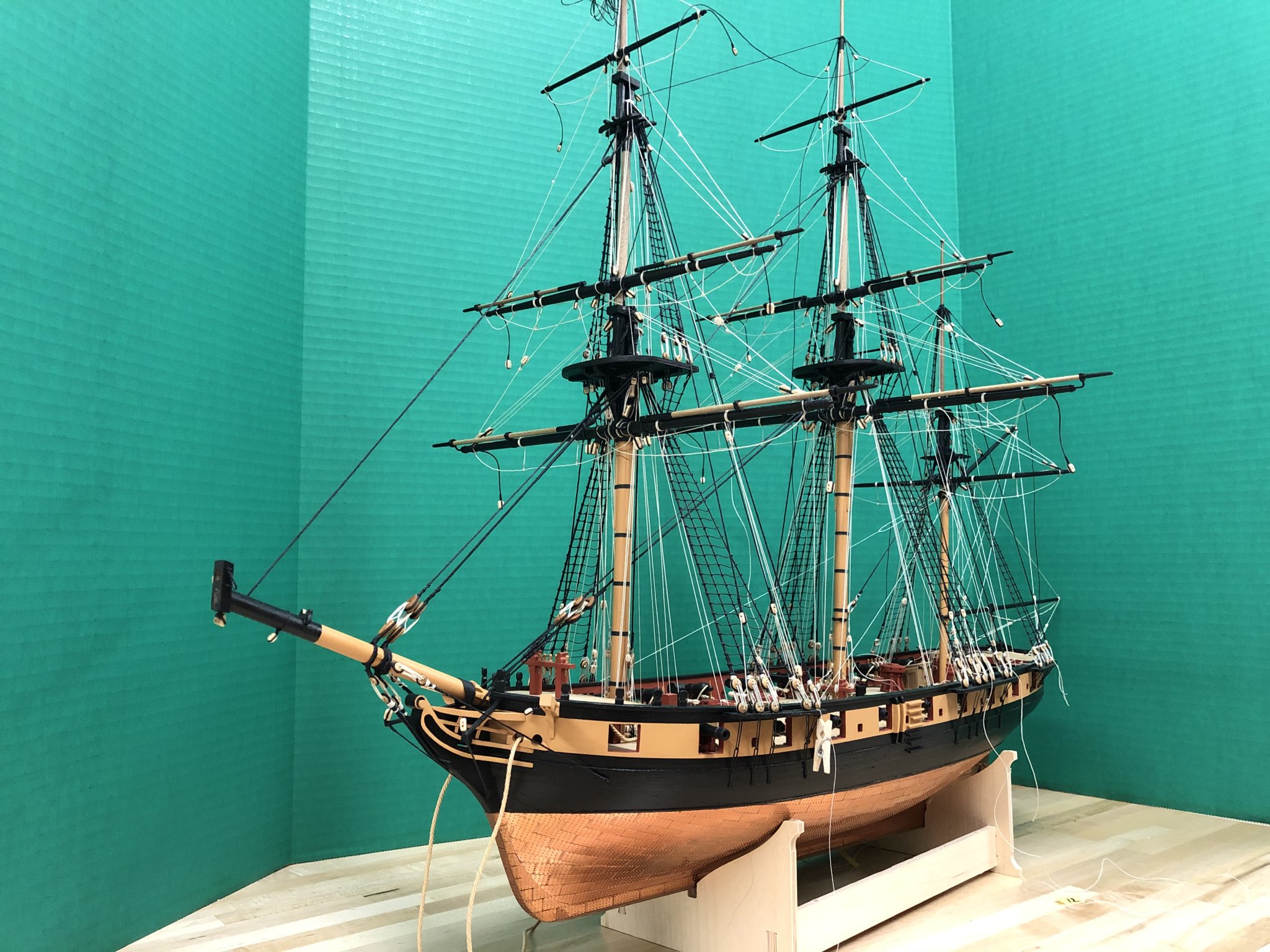
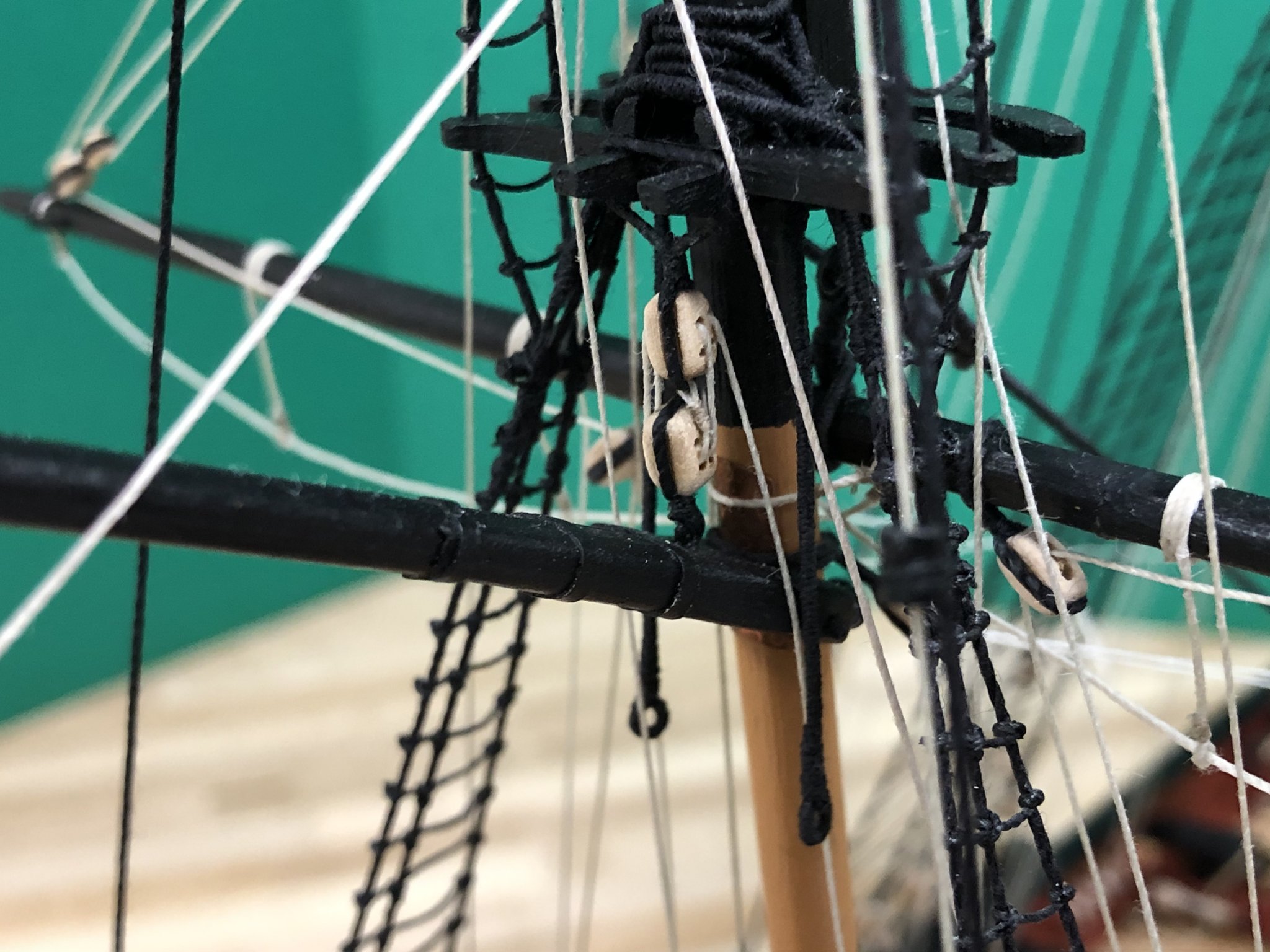
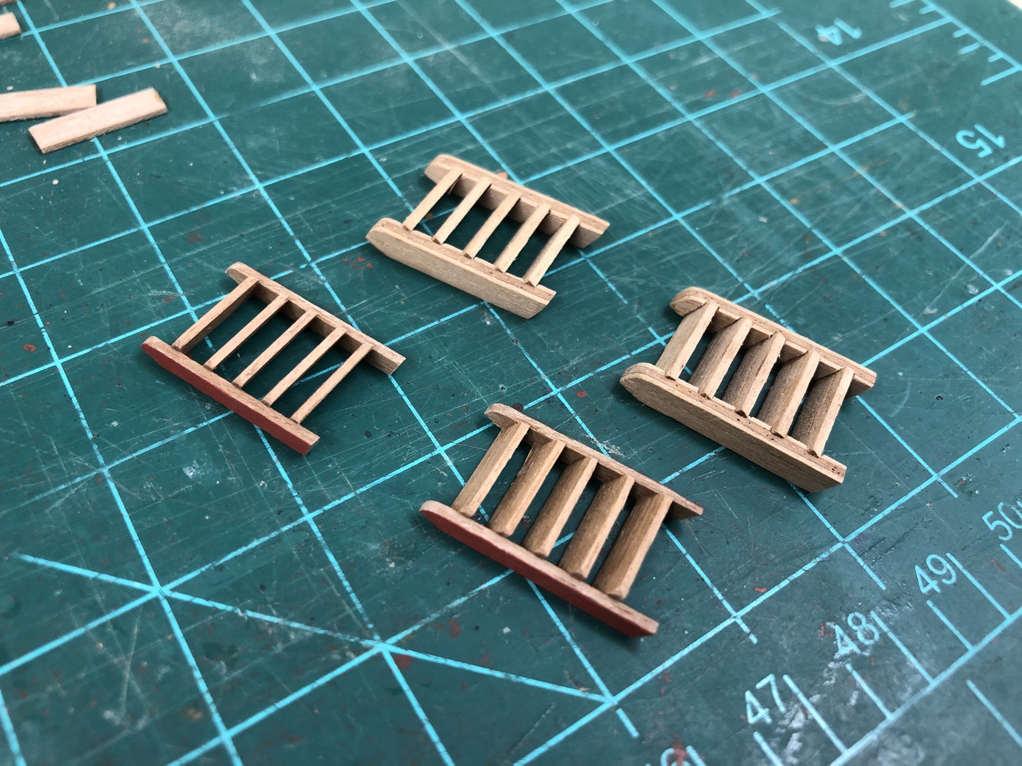
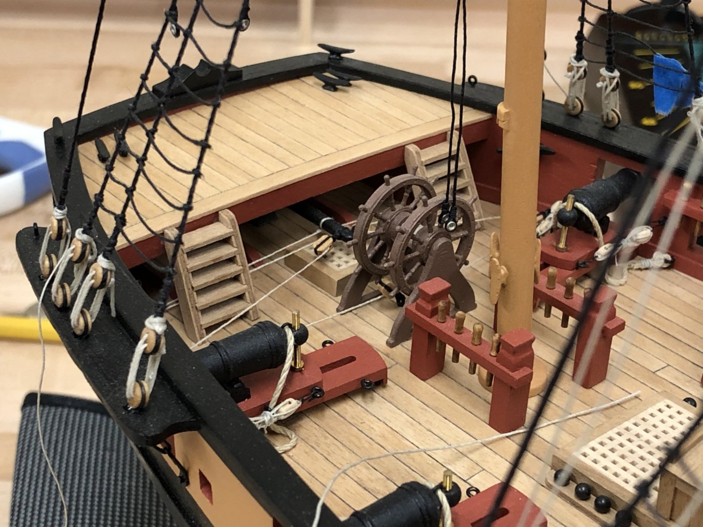
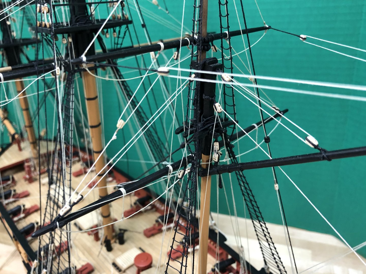
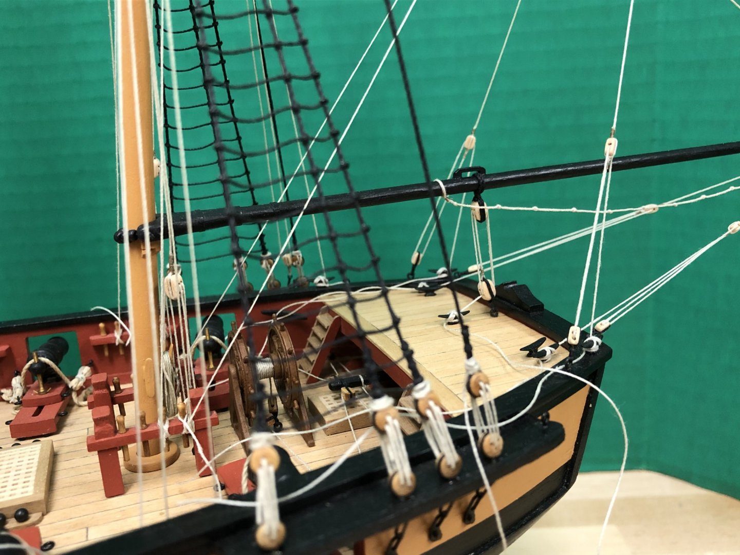
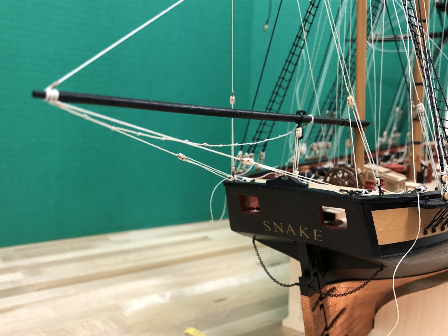
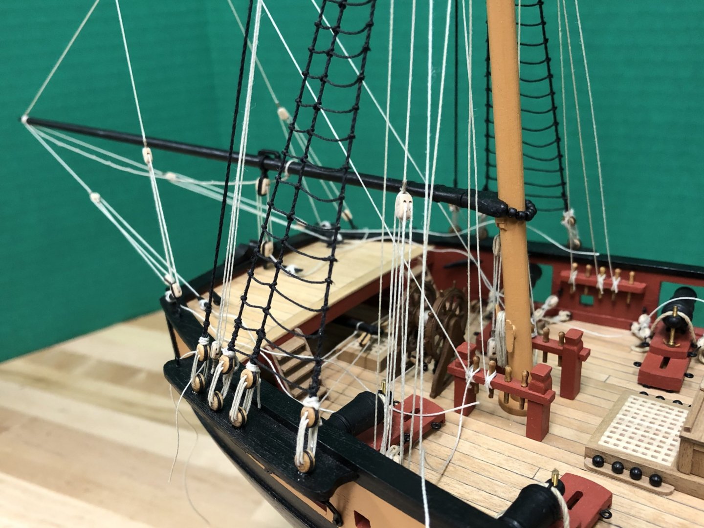
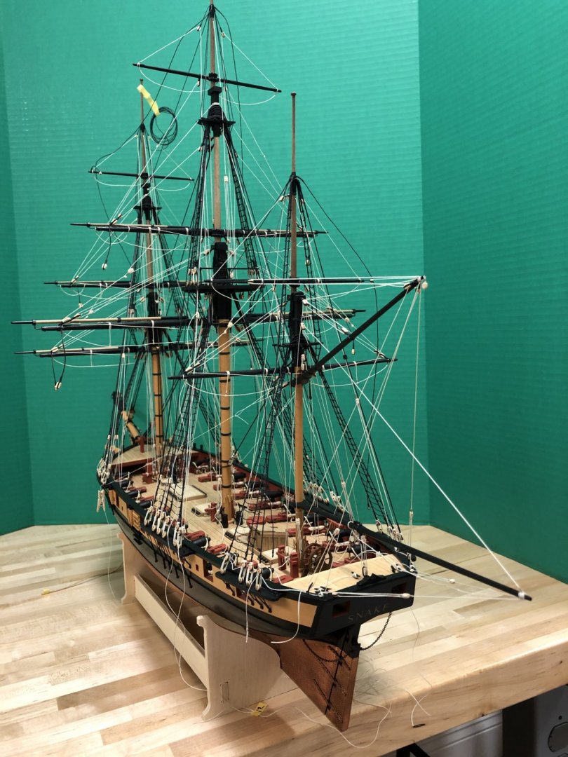
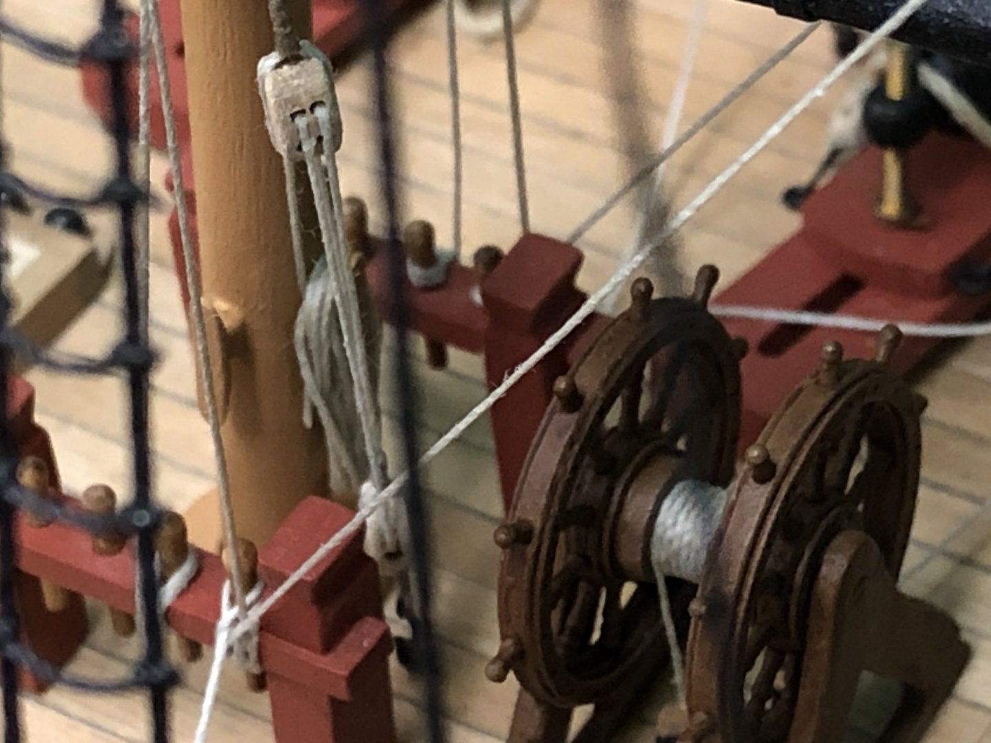
The Mizzen has arisen: I can see why build logs tend to neglect rigging relegating it to a bit of a dark art - its so hard to reach a point where one can step back and say 'done' because nothing quite seems to get finished before its necessary to do something else before its too late. Anyway, the mizzen rigging is now essentially complete. This area proved to one of the more challenging so far 'learning the ropes', but also just because of the increased fiddliness factor and decreased access. The plans also proved more challenging in this area due to their either lack of clarity or incompleteness. Before starting, this was my last chance to address some things that have been annoying me. The kit supplied ladders going to the stern platform just seemed too bulky, so these were ripped off and replaced with custom made items that just felt a little more to scale, and less visually obtrusive. These proved challenging to make in walnut due to the splinter factor, but necessary to avoid introducing a new wood. The ships wheel was also given some coats of a wash to try and make it a bit attractive from the flat brown colour I had used way back when I started (Pre-fix situation below): Rigging could then proceed, planning ahead proved key due to the many elements that need to be fitted in a very tight space, especially below the tops (tye, parrels throat halliard etc). Petersson's Rigging Period Ship Models and Lever's Young Officers Sheet Anchor provide invaluable to bridge contradictions and lack of clarity in the plans. Items of note as follows: Boom Sheets - went with single vs a double arrangement as illustrated on the plans as I couldn't find another example like this Gaff throat halliard - the positioning of the gaff is slightly different on each plan, I had to lower my original placement to allow for the two double 5mm blocks, luckily the pin hole was obscured Single boom horse - Common practice seems to have a knotted horses on either side of the boom. I just couldn't get this to look right and the image of a young schoolboy with rather large and unruly ears kept coming to mind....so in the end I just went with a single and it seems to do the trick other than to purists. Blocks for main topsail brace - One of the first blocks I had installed has to be removed, a double block on the mizzen for the main topsail braces as indicated on the plans. It was clear that this just wouldn't work with the crossjack and gaff in place as it needs to sit above the gaff. I elected to remove and replace with 2 single 5mm blocks with a longer clearance from the mast to avoid interfering with the various rigging elements in this space as illustrated in Petersson. These are held temporarily in place with sewing thread. Close up pictures of where things ended up that hopefully can assist others (errors are of course mine): Finally, some overall shots...


- 800 replies
-
- 27
-
-
- snake
- caldercraft
- (and 1 more)
-
Great start David, keep going! Don't think you'll experience too many challenges as long as you keep thinking ahead. I always wonder why people think coppering is an 'easy' option vs planking.
-
Catching up Peter, you really do have a great looking model coming together. Regarding the mizzen, the rake of the masts increases aft with only the foremast being somewhat near vertical, the angle of yours look similar to mine. The pin rail does look awkward with that positioning and access must be a little problematic especially with the wheel being for'd of the mizzen as well. Its funny how results in 3 dimensions can come out with surprising results when referring to 2D plans. I share your thoughts on the kit ladders, if you have a circular sander you could make up a simple jig to make your own. Takes a bit if fiddling but can give pleasing results, simply gluing the ends of the steps to the riser proves to be sturdy enough (recognizing that they're not getting much use 🙂 )
-
I have attached copper plates directly to unfinished (other than sanded) wood without issue using higher viscosity CA. One consideration is that using plates invariably leaves very slight gaps (probably depending on skill level!) so having a 'similar' colour underneath helps minimize the visibility of these imperfections.
-
Hi Tom, looking good. One question, see that you have the anchor stock parallels to the arms, I've never seen these anything other than being set at a right angle to each other.
-
You did a great job on that top and butt planking which really jumps out now, hope it stays visible with the guns in place. Good luck with the copper, remember its a marathon not a sprint 🙂
-
Its only a 6hr drive (give or take) not counting New York, Philadelphia or Baltimore traffic.... 🙂
-
Welcome Will, your models look great. Definitely consider starting a build log, that way you will certainly get plenty of support and advice along the way, definitely the best way to get the most out of this community.
-
That looks good Mark. Did you adjust the stern profile to account for the curvature of the fascia?
-
They look great Eamonn, well done. How did you do the puddening around the anchor loop (esp. starting and finishing), need to get to that myself but can't quite get my head around it....everyone else seems to get it done without a problem.
- 1,039 replies
-
- 1
-
-
- ballahoo
- caldercraft
- (and 2 more)
-
That looks spot on. I would love to be able to work with these drafting tools, very educational.
-
That some very nice coppering, well done. The thickness (from the hull) of the batten tends to exacerbate the optical illusion of the waterline not being straight, so the thinner the better, but you look have to nailed it.
-
Hi Thunder, don't know the answers to your earlier questions on iron hoops. These very small time period seems to be such a focused time for so many evolutions and other variables that narrowing something down to a 4 year period is probably an exercise in futility so you probably have the license to do what you want. That's a really nice looking capstan.