Beef Wellington
-
Posts
2,249 -
Joined
-
Last visited
Content Type
Profiles
Forums
Gallery
Events
Everything posted by Beef Wellington
-
 ...and start a build log so everyone can follow along and help answer the next question that will undoubtedly arise 🙂
 -
Hi Jim, just a thought, I wonder if you were to go with the 'yellower' initial colour, it would fit in better to my eye. You could try doing the spots in relief with a drill bit, and highlighting with a slightly darker colour which I think would be a little subtler. All artistic opinion of course. Looks great in any event.
-
Really nice result on the cap rail edge molding, really seems to finish things off and all the detail blends in beautifully. I similarly ponder the rear ports, I'm not convinced .they would be workable on the Snake/Cruiser class either but they are there. I can only envisage them being used for rope work, mooring etc similar to the ubiquitous lower ports seen on larger ships when clearly there are also more practical, better positioned true stern gun ports - in any event they look great.
- 574 replies
-
- 3
-

-
- cheerful
- Syren Ship Model Company
- (and 1 more)
-
Looking very nice Mark, I can't help but feel this would make a nice kit. Have you considered going there?
-
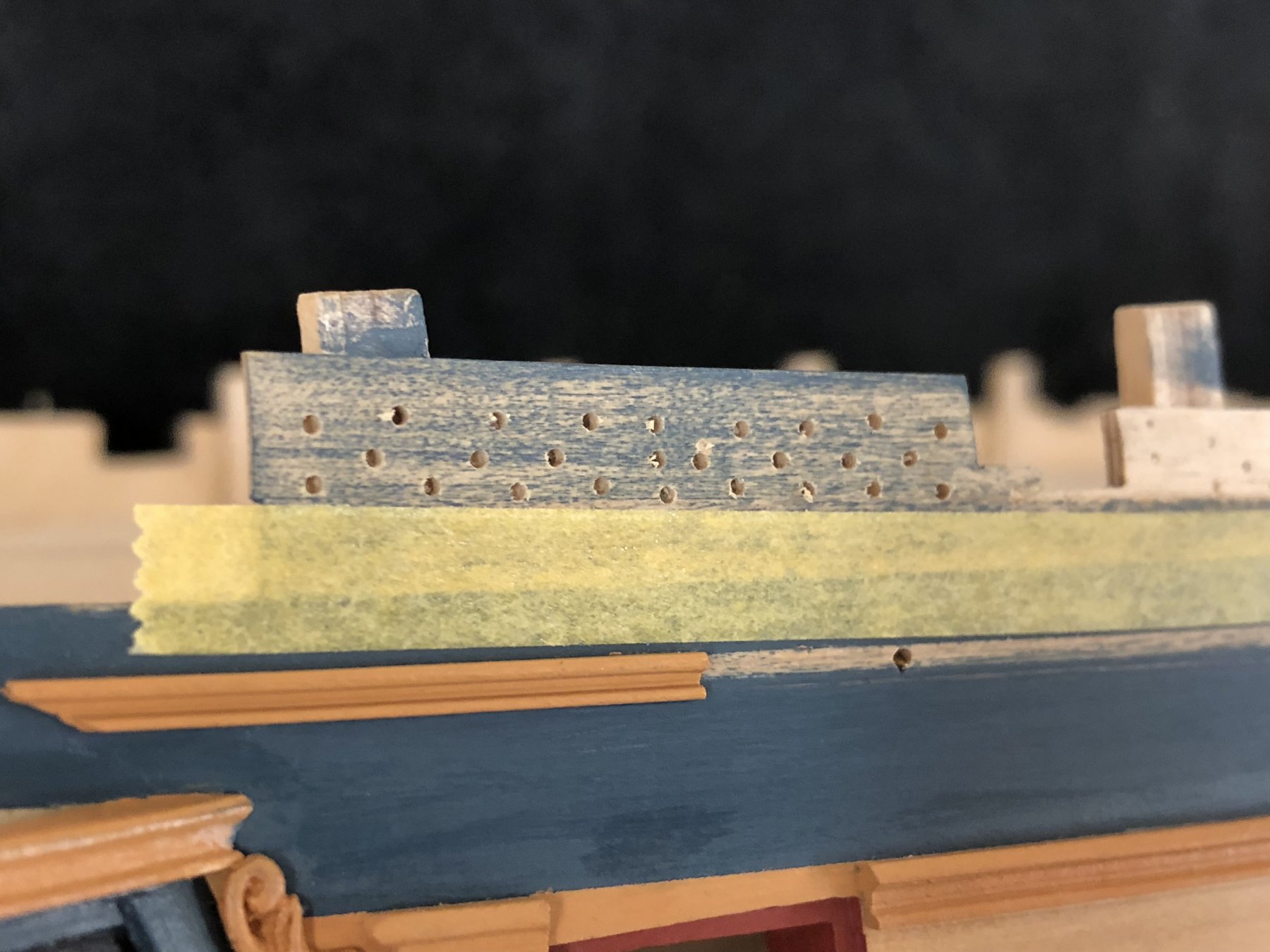
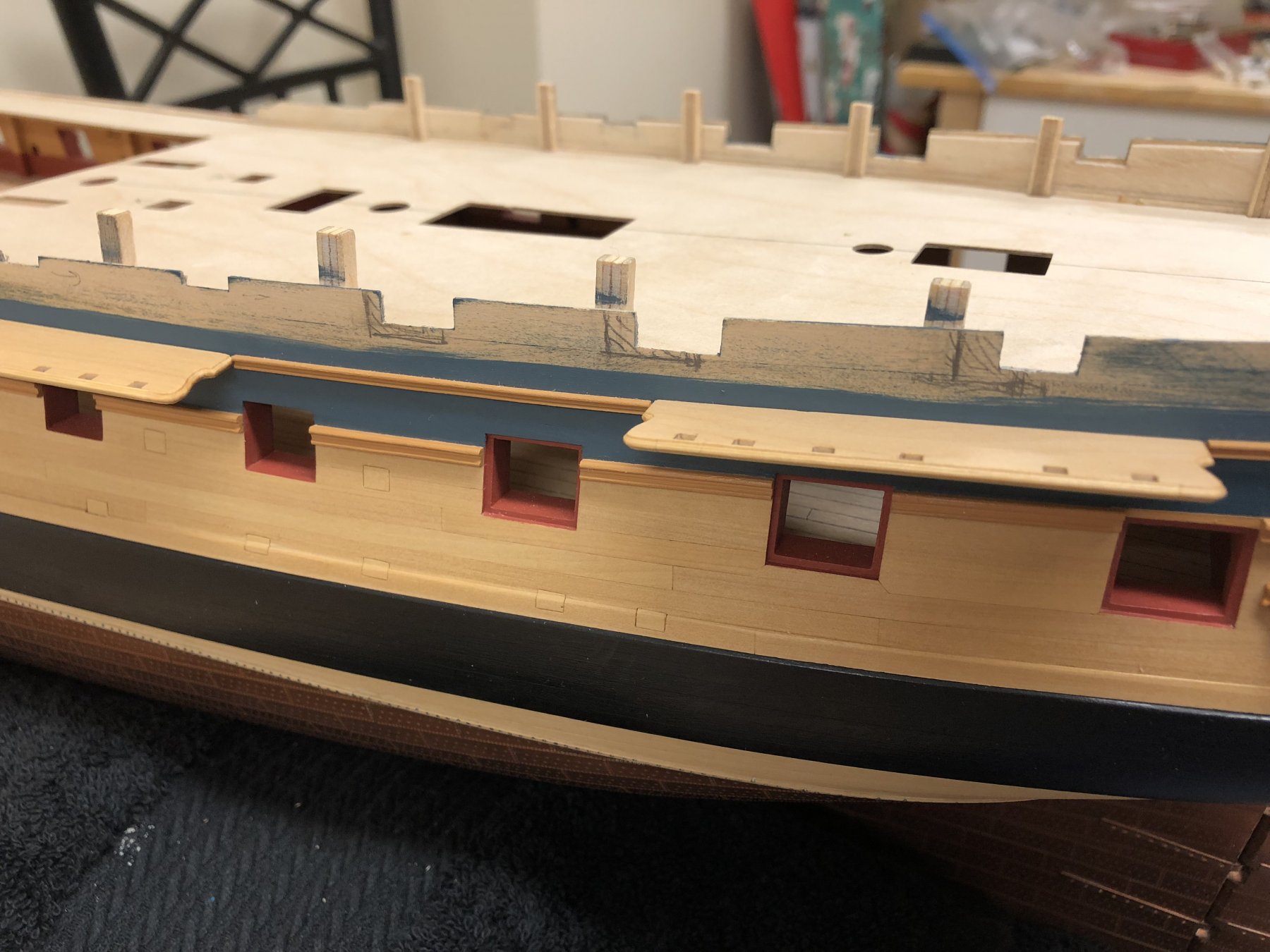
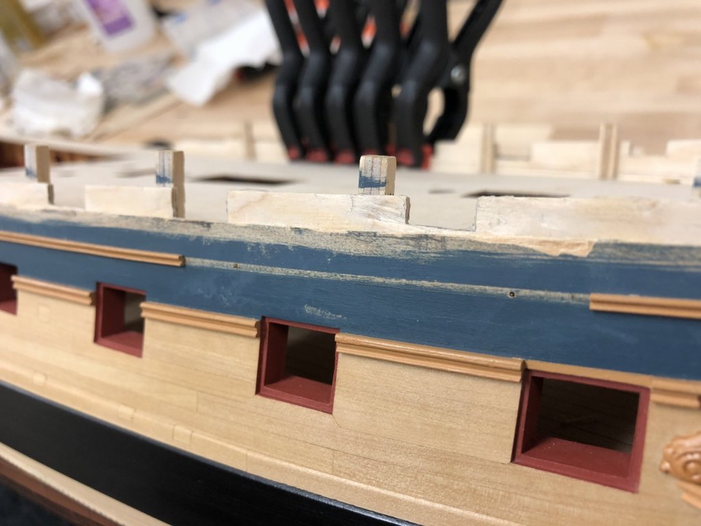
Destruction... Need to jump in and get going with the destruction to correct the gun ports so this doesn't derail me. There will be 3 or 4 ports per side that need to be moved, so doing individually would not make sense. Fortuitously, I had used a strip of 6mm wide box for the uppermost strake. With one minor exception, the rough cut ports don't extend below this so replacing this one strake seems to be the way to go. Started off on the port side using isopropyl alcohol and a sharp blade to try to pry the 1mm thick strip from the 1.5mm thick template. Although I eventually got there, its a real dogs breakfast (mess). I just couldn't get the isopropyl to penetrate where I needed it sufficiently without compromising the surrounding structures (the template is laminate strip which will de-bond as well if too much isopropyl is used). As you can see in the pictures, a couple of shards got stripped away in the process where the box strip had been edge glued and but not sufficiently softened. The isopropyl also got onto the painted surface below and marred the finish, so this will need touching up. Once replaced, filled and finished, hoping this will not be noticeable. Before tackling the starboard side, the approach needed to be amended to allow the isopropyl to penetrate more thoroughly and evenly. Took a while, drilled a multitude of holes in the strake to be removed and then applied the isopropyl. Despite taking a while to drill, this was SO much easier and gave a MUCH cleaner result. It also allowed the glued edges to soften sufficiently to debond cleanly. Now the scary part is over, the strake can be replaced and the template ports filled before getting back to where I was with the channels....


-
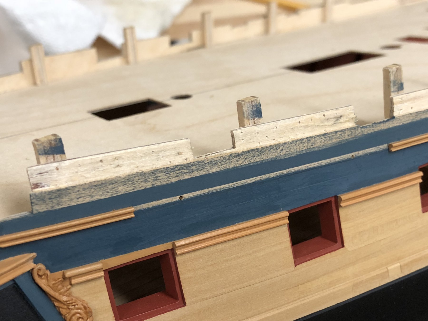
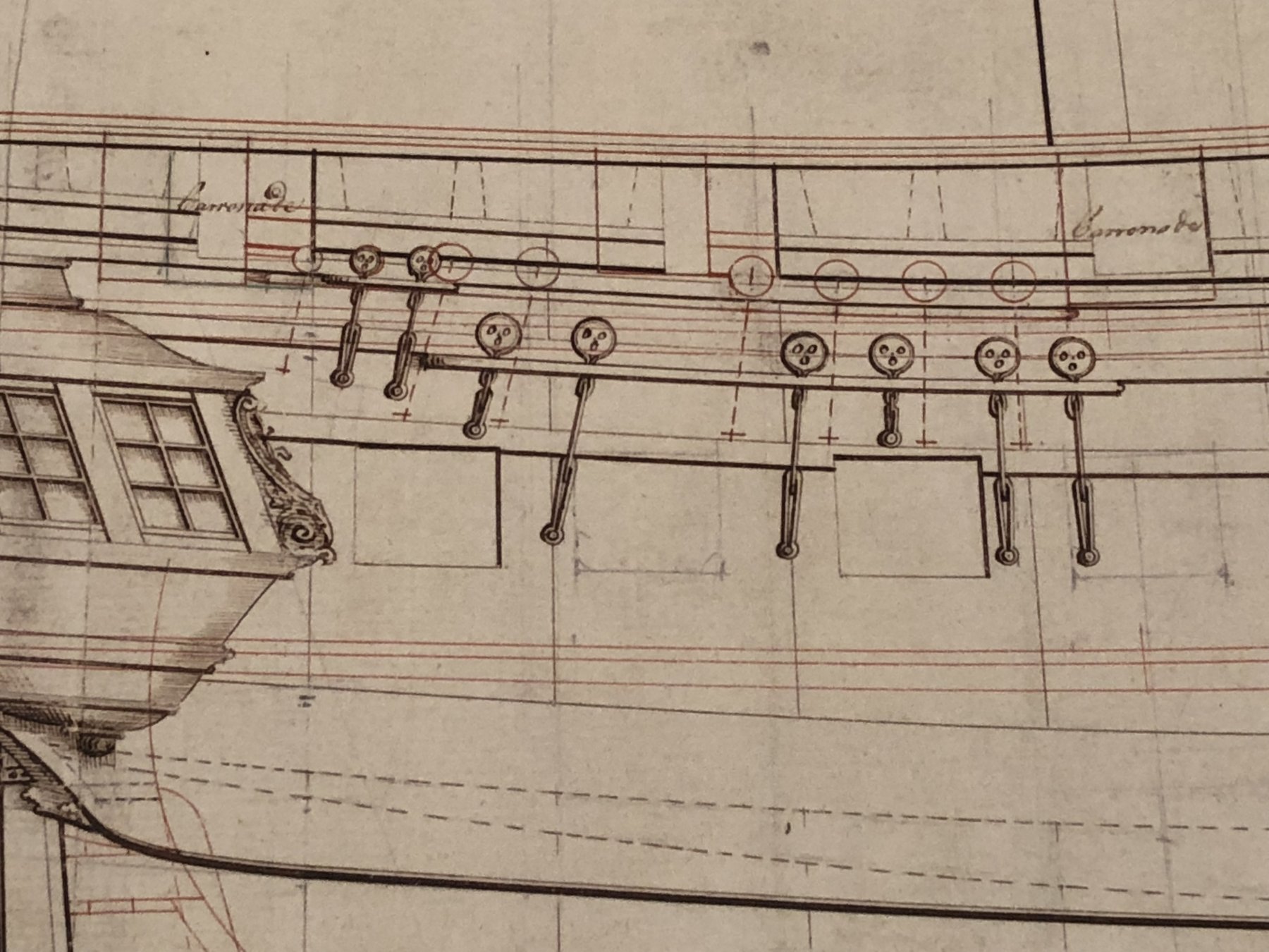
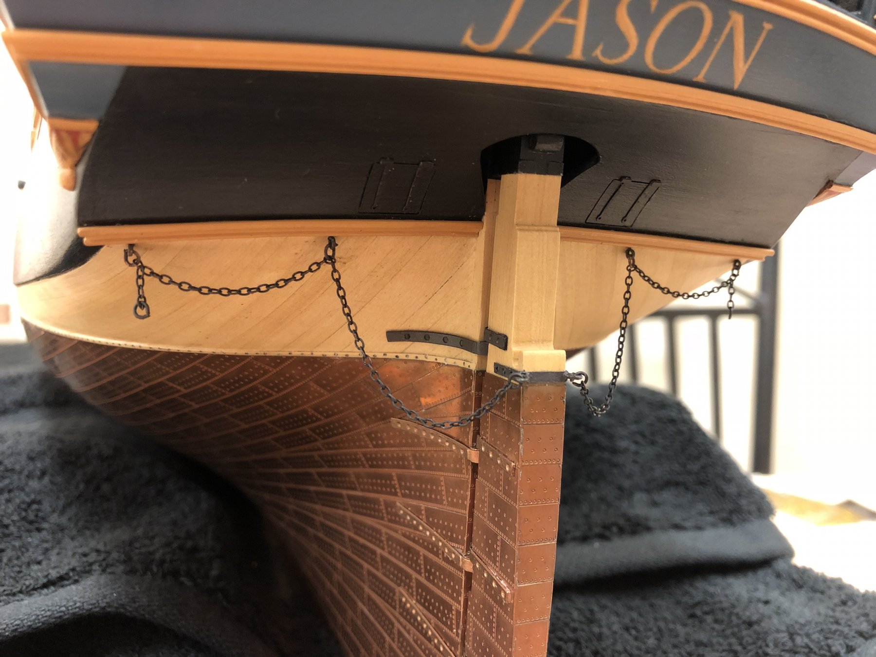
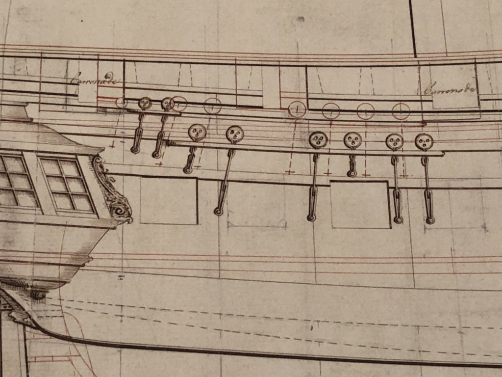
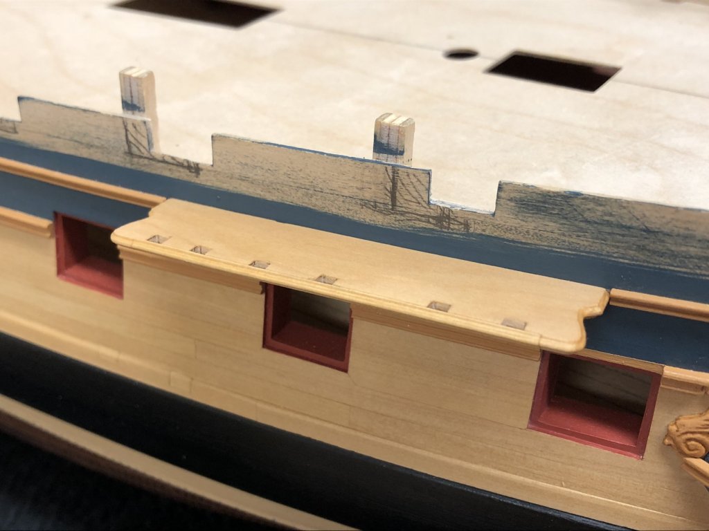
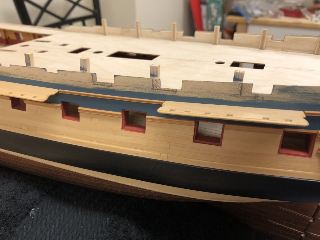
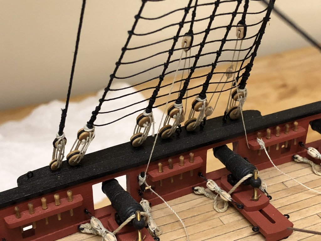
Thanks for the encouragement gents, certainly helps one stay motivated. Channels: I realize I'm continuing to bounce around, so apologies if this is not the most sequential log. Have been continuing to work on the deck fittings, none of which are glued in place yet (posts to come), but diverted to the channels. I think it will makes sense to have the channels and chains in place before any of the cannons are finally fitted - they just seem to be too exposed to not court disaster. This seems a "damned if you do, damned if you don't" situation so any advise here would be gratefully received. I'd share the approach to the channels in an earlier post, so luckily work was more just final finishing. I wanted to introduce the rather pleasing profile on the edge as it seems to reduce the perceived bulk of the channel noticeably to my eye. I have to say, this has been some of the most challenging 'scraper work' I've yet done. Getting clean (or as clean as I can!) edges on all of the compound curvatures, as well as dealing with scraping across end grains at the fore and aftmost faces proved a real challenge. To add to this, I realized that the batten that keeps the chains in place also needs to be profiled. I'm taking the approach of temporarily gluing the batten in place, profiling, and then will de-bond using rubbing alcohol. The thinking being that once these are shaped, it should be relatively straightforward to glue permanently once the deadeyes and chains are in position. Each one will be carefully notated so I can match them up again. I've put on a very thin coat of wipe on poly to enhance the visibility of the profiles surface and see where I am...there will definitely need to be a little fine tuning once all are done, bit hopefully this illustrates. I'm following the NMM plans as closely as I can, which show both the initial draft with open quarterdeck, as well as the changes when the quarterdeck bulwark was built up. Not only does the position of the channels change, but the alignment of the chains. Not having had the plans earlier, I had used the kit supplied template as a foundation..... I have now reached the point in the build that every Artois class builder doing an open bulwark version seams to reach, which is the realization that the position of the quarterdeck ports need to be modified - wish I'd ordered the NMM plans sooner. The gunport openings changed when the position of the channels was changed with the addition of the built up bulwark. This will require the position of the gun ports to be corrected. How I wish that I had simply planked over the kit template rather than planking around the ports, it would have made a fix unnecessary. I'm moving on while I consider how best to do this.
-
Greeting Stergios, not sure if this helps. I remember being very confused by this myself. Here is what I did to solve the problem, I can't guarantee it is the correct solution, but sharing in case it gives you a better idea. You can see its still work in progress!
- 1,144 replies
-
- 2
-
-
- snake
- caldercraft
- (and 1 more)
-
Don't think you need to worry too much about hiding the gunports, however you plank that shouldn't be too difficult to do - whether you plank over and then cut out, or shape planks prior to gluing in place (definitely better for the ports with lids). Getting the right line for the wales is so visually important later on so definitely worth taking your time to get it right.
-
Playing catchup, what a beautiful ship and excellent execution, love the finish, colours..everything just coming together so well. Nicely done!
- 467 replies
-
- 5
-
-
- mikasa
- wave models
- (and 1 more)
-
Rob, you're cabin bulkhead came together really nicely done. Its a shame the cabin area of this kit doesn't lend itself to opening up the deck, the last bulkhead with the gap the center still glares at me. I agree with you on the use of white, wonder if you've looked at the Admiralty 'Ivory' colour? Its much less garish in tone and might really allow the detail to show through with the upper deck in place. Deck shot looks great, and to think, "real" ammo! 🙂
-
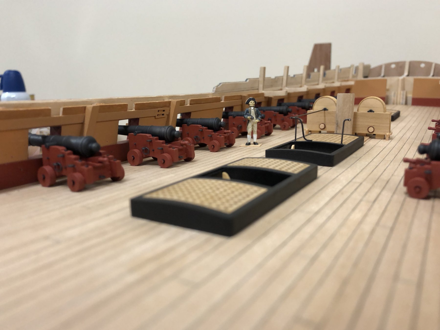
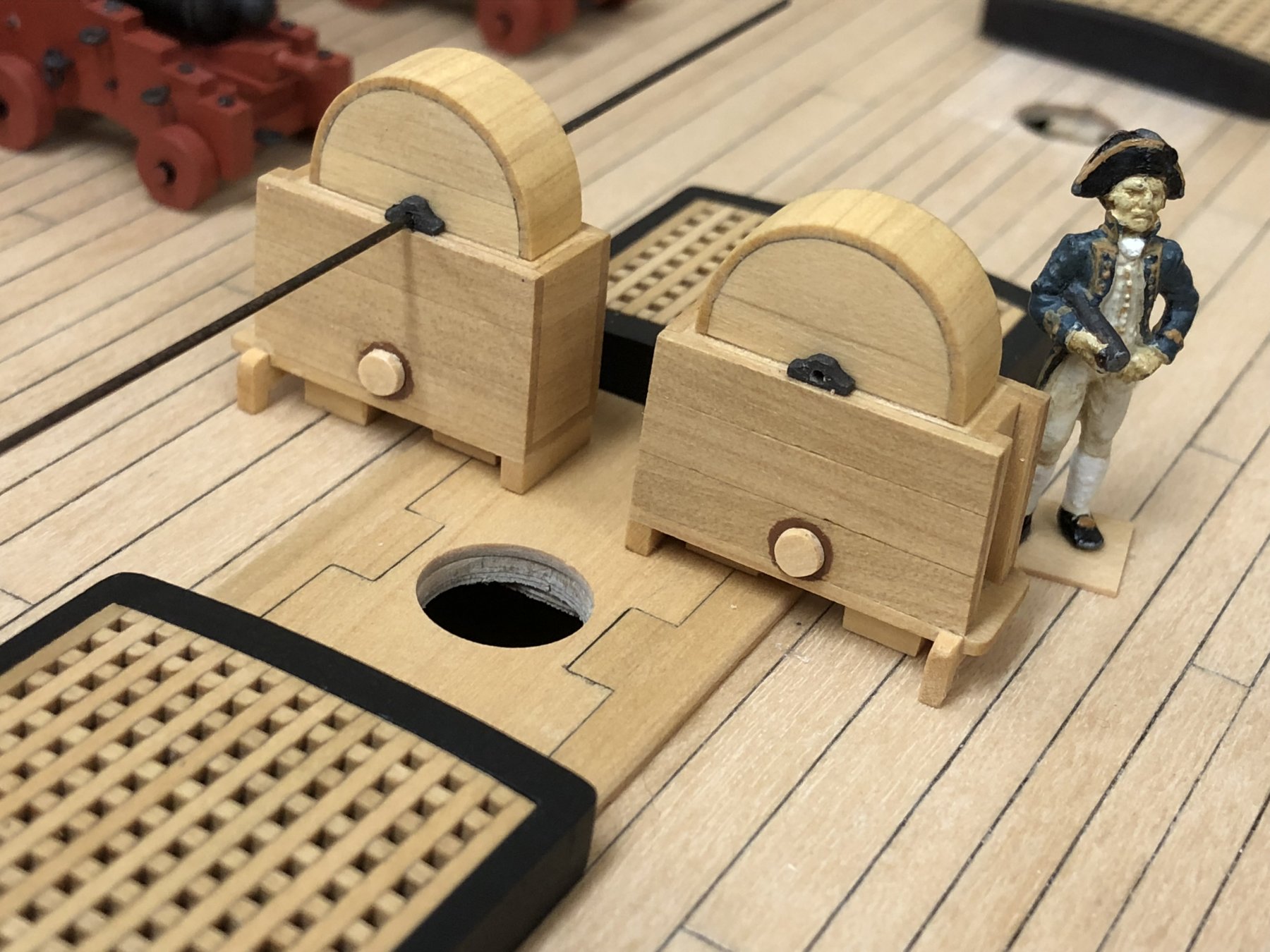
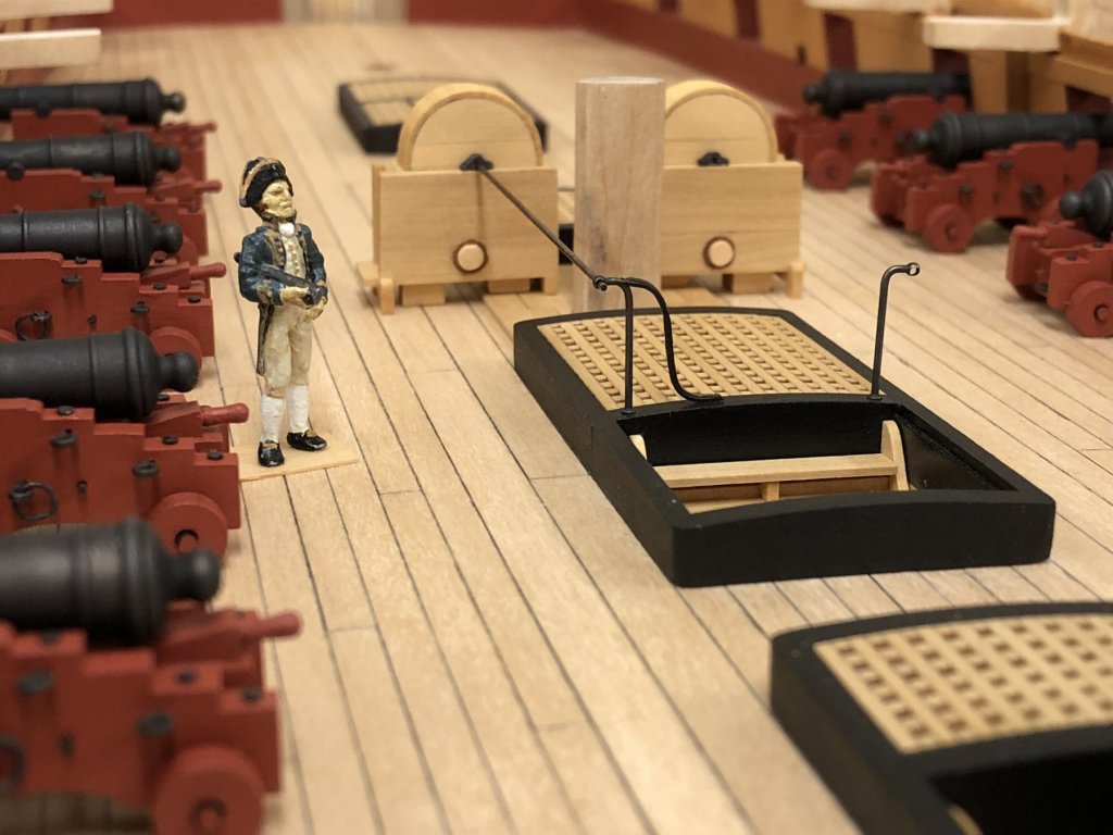
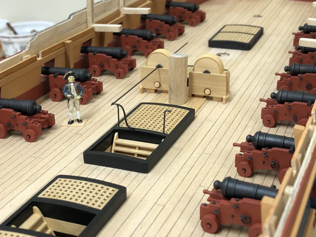
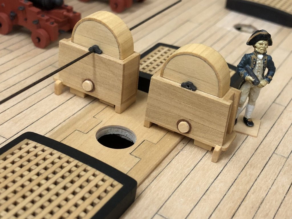
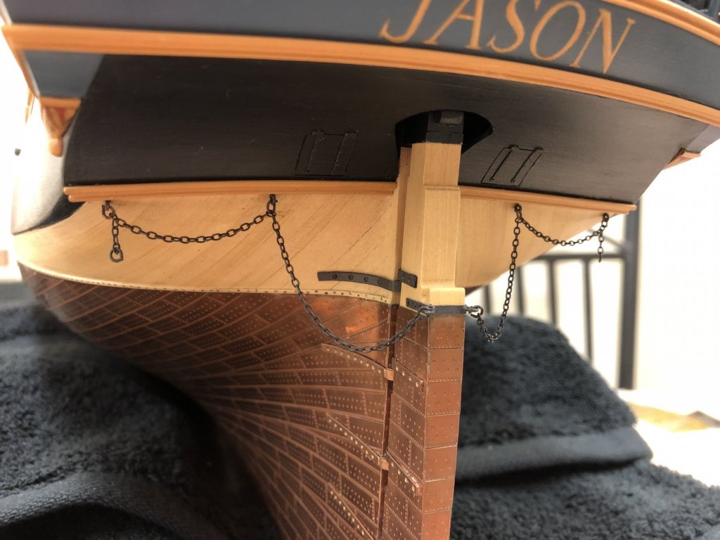
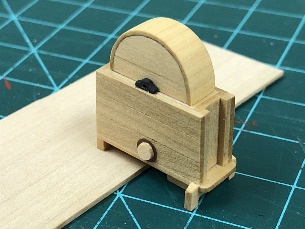
Interim update: Anchor chain is on finally, been putting this off but really had to get it done so I could permanently 'right-side' the model...its amazing how many configurations there are on models and there really doesn't seem to be a standard way. Next up, as a break from the repetitious chore of the gun carriages, was to finish the pumps. I'd been overthinking how to cover the curved surface of the pump covers. In the end, 1x2mm strip was used, with one side angled - wasn't as bad as I thought. Once attached, the thickness was sanded down to try to get a more scale look. Winch bearingsfor the pumps were shaped from strip and painted 'dark iron'. Brown paint was used to simulate the leather washer for the cistern plugs. These will be a little obscured eventually, but I think these details will be visible. Once the pumps were completed, the next logical step is to figure out how to support these at the main hatch. The kits indicates using wooden strip for this, but contemporary models show an iron bracket and this is what I' like to try to replicate as it seems more appropriate. The main part of the bracket was made using an RB models stanchion, bent to shape and with the hole enlarged with a 0.8mm drill bit to accept the winches that will eventually be installed. The height of these needs to be the same as the winch bearings so that the winch will be parallel to the deck, and they need to be parallel to the deck and over the coamings so the main hatch is not obscured - so this essentially determines the lateral placement of the pumps. I will add an additional bracket which would have been necessary for strength, and you can see a trial made up from some scrap PE to illustrate which I think will do the trick. I found thinking this through all rather intriguing as there seem to be some obvious problems. For anyone coming from the lower deck, the ladder feads directly over the main hatch grating, and the winch brackets definitely seem to get in the way a bit here here, in addition to having to navigating the pump winches. I can't figure out for the life of me why the ladders don't lead up forward rather than aft as this would seem to be much more practical, but this orientation is clearly shown on the original plans, AOTS Diana, as well as contemporary models...if anyone knows why, please say so! Now that the positioning of the pump winches is known, the placement of the pillars for the main topsail sheet and main jeer bitts can be determined...which will probably be the next diversion.
-
Lovely model Lin and great execution, shame you haven't shared progress up to now! Will certainly be following you from here on, great subject matter.
-
Stern looking very nice indeed Rob, well done! BTW, the two outside lights were false lights, similarly the foremost and aftmost light in the stern gallery. Looking at Trincomalee shows this in practice, though think those were painted a lighter green. Seems it was all to keep the proportion and elegance of the stern rather than for practicality.
-
That's a nice mock up you have going there. I think you've already found the solution, to mount on a deckblock. Mounting outside seems to have been of the earlier practices once carronades came into use. If you look at other's logs, you'll see that this problem has been experienced by every Snake builder so you're in good company 🙂 As for the chequer, down to captains orders and what you think looks good. On Victory the proportions are a little different on each row of ports. The consistency seem to be to roughly hit the top of the ports for the upper line, but extend slightly below the bottom. One contemporary and earlier practice was to paint a similar pattern, but following the line of wale which looks subtly different.
-
Hi Carl, this is one of those things that is very hard to capture in a photo (at least on my iPhone 'camera'). The finish does have a pleasant sheen, certainly not 'matte', it also brings a more consistent colour finish to all barrels as each one does tend to have a slightly different sheen and/or colour hue - definitely still at the 'artistic' stage rather than 'repeatable scientific process'. 🤐
-
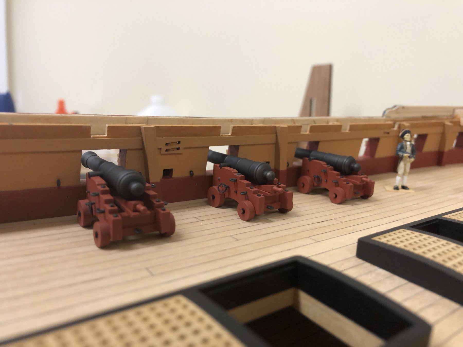
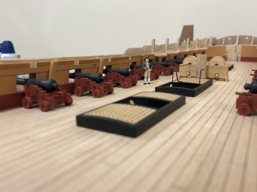
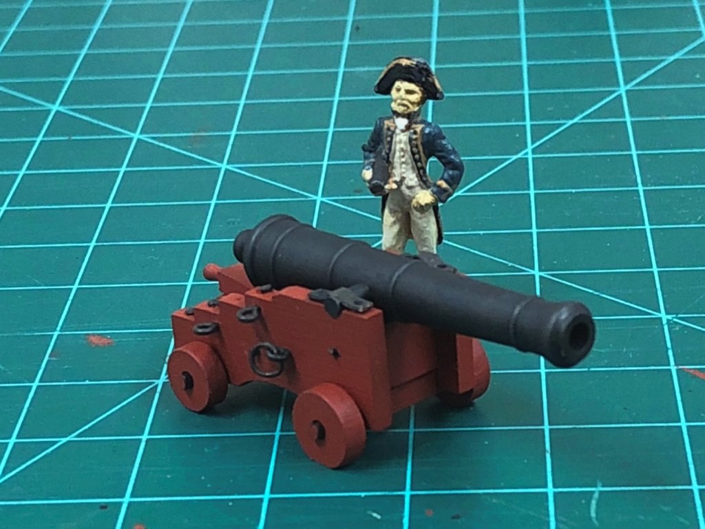
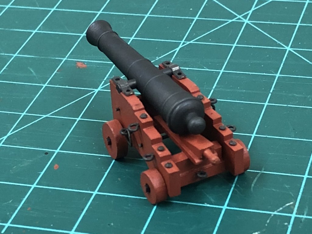
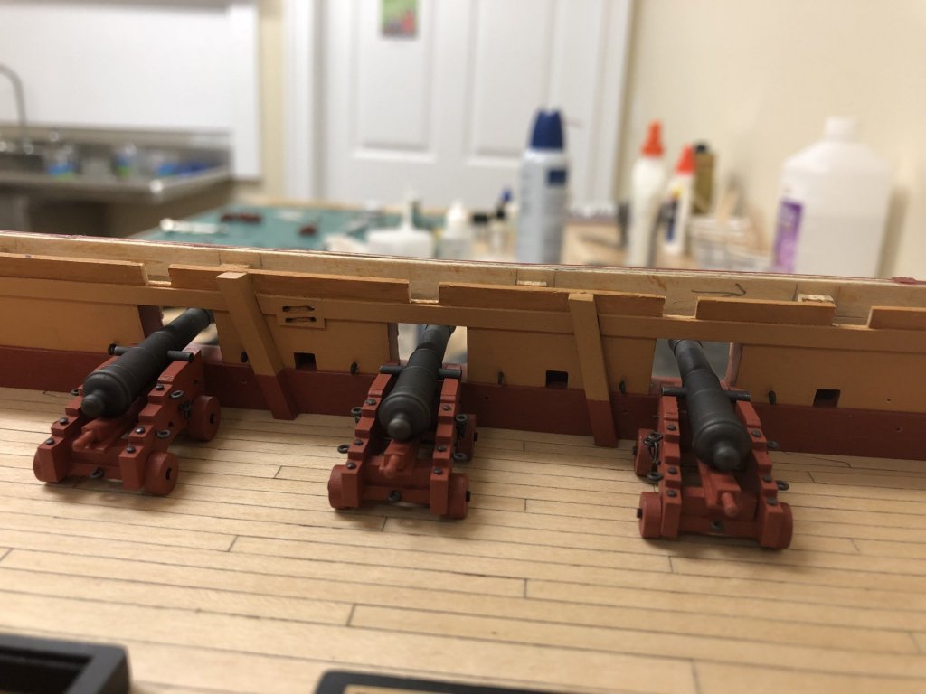
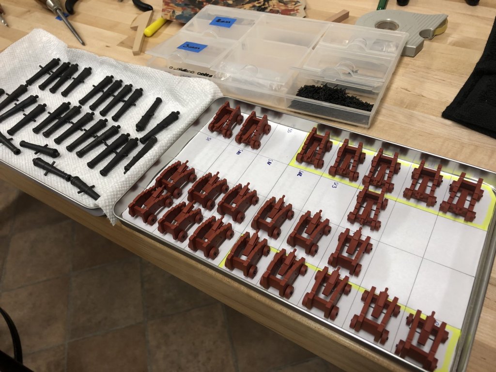
Gun Carriages: Nothing revolutionary, prototype gun carriage has been completed after putting on some more coats of paint to the carriages. Learning experience here is to use as little paint on metal items as possible, all ring bolts and ring bolts have been chemically blackened. Cannon barrels and ring bolts have been finished with Testors clear matt lacquer to eliminate the shine still inherent to the blackened surface. The carriage bolts are model railway/railroad track pins which have a shallow domed head, these come painted black, so the head was painted with 'dark iron' before attaching. I had experimented with countersinking these on a spare, but this seemed a little over fussy, and also just using wire cut off wire but felt these looked too dainty. Event though many of these will be obscured by the deck, I will probably build all of these as per the prototype in case glimpses can be seen through various openings. The guns that are highly visible will likely get a little more detailing but I'll decide to what extent when all of these are done. Its a little disconcerting when I sat back a figured out what will be needed, and this is just the upper deck. Everything is at least now ready for assembly.... ringbolts - 336 blackened (7 per carriage, 4 per bulwark, 1 deck bolt) Domed pins - 168 (6 per carriage) 3mm rings - 112 (2 per carriage for breaching rope, 2 per gunport for breaching rope) 2mm rings - 28 (1 per gunport deckring) So far 3 carriages have been built up, as the best method for construction becomes clearer, these do seem to be going together more quickly, but still not quickly 🙂

-
Very nice clean work Bob, I love the fine details that you achieve.
- 359 replies
-
- 3
-
-
- prince de neufchatel
- model shipways
- (and 1 more)
-
Very very nice result with those copper plates Peter, well done indeed. Keep going!
- 366 replies
-
- 3
-
-
- bellerophon
- victory models
- (and 2 more)
-
Very nice looking cannon Bob, starting to deal with these myself and I you're right that it is a rather challenging/repetitive task. One observation, I don't think the there would be a block strapped to the rear axle, rather this would be attached via a hook.
-
Hi Rob, love that last quarter shot, most definitely her best angle in my opinion! Picking up on my cannons as well, I'm intrigued by the barrels that came in your kit, they are definitely different to what was supplied in mine, much more appropriate. They look very nice indeed.
-
Hi David, Picks up instruction manual blowing an inch of dust off the top 🙂 I seem to recall that I ordered some wider strip because 1x6mm did not seem large enough....I also seem to recall this was probably the last time I looked at the instructions because they are really not that helpful. For what its worth, the instructions say the following... "Gun port dimensions should be 16mm long, 14mm wide and 30mm apart (note: although I disagreed with the latter dimension as per my log...) Gunport without lids can be framed using 1x6mm walnut strip. Cut to length and glue the vertical sides first, followed by the top and bottom frames. When complete, sand the outer edges flush with sides of hull. The gunports with lids are framed after the application of the second planking."
-
Hi all for the interest and the kind words and likes! Have been on a bit of a hiatus, other distractions and a need for a little break. Think I'm now back in the groove with the passion back again....looking forward to catching up on everyone else's progress on their builds. Tim - the photos are maybe being overly kind, no airbrush, just regular brushes. I generally don't dilute the Admiralty paints, but do tend to use a damp brush. The blue on the hull is an exception where layers of dilute blue have been built up to avoid brush marks where possible, the Tamiya paints don't really lend themselves to this as much, but it seems to work.
-
Hi Andy, looking forward to some shots of your updates. BTW....you're not the only one to stall regularly, I needed to step away myself from the shipyard and am just getting the bug to go back and continue.