


James H
-
Posts
5,537 -
Joined
-
Last visited
Content Type
Profiles
Forums
Gallery
Events
Posts posted by James H
-
-
-
Stunning! Lovely work, Rusty.
- Canute and CaptainSteve
-
 2
2
-
-
1 minute ago, grsjax said:
Just a suggested addition to the list of kits for people with a little experience, The Model Shipways kit the skipjack "Willie Bennett". Great kit that is not to hard to build and has really clear, easy .o follow instructions.
Cheers. I'll add it.
-
That is a work of art. Just superb.
-
Remember that we had to compile this list aiming at the average modeller who may never have built in wood.
Some modellers will take to the hobby like a duck to water, whilst others may not. Then there is always the unknown factor about a newcomer being used to working in wood before they make their first ship. The list is like a line of best fit, and will generally apply, but may not have applied to you personally. It's simply a guide.
We will doubtless lose many to this hobby because their first project was too ambitious and they crashed and burned. It does happen, in every hobby. You generally still need to walk before you can run. Many newcomers will need something simple and not that 20yr HMS Victory project which could last 6 months and sap their enthusiasm.
-
-
20 hours ago, Y.T. said:
I understand and believe it is good to promote the hobby (wooden ship building). I however do not believe that this hobby is for everyone. Many disappointments are awaiting those who are not up to it. Very sorry to say this

That is very true. I hope this topic will help those that do have an inkling of what is before them.
-
5 hours ago, jhearl said:
I'm a little surprised you didn't mention any of Bluejacket's entry-level kits. The first kit I successfully completed many years ago was the Grand Banks dory. As well, I think some of the easier solid-hull kits, like Yankee Hero are a good choice for those with little or no experience.
Cheers -
John
If you can send me an amendment for specific areas, I'll post it into the topic.
-
11 minutes ago, amateur said:
Just a question: The slip can hold keel, stern and bulkheads into position. It can even be used to turn the model side-upwards. But it looks as if there is little margin when the stern has not the same thickness as the MDF-piece. (the clamps in step 6 and 16 look rather rigid to me) Is there any flexibility when your stern is thicker/thinner than the one of the example-model?
Jan
There is flexibility there, but I put in my article that I would use shim pieces to pack out the clamps as much as possible.
- Keith Black, mtaylor, thibaultron and 2 others
-
5
-
-
10 hours ago, tigerdvr said:
I've been using mine for a couple of years now. Big enough to easily handle the ME Confederacy. Configuration is very flexible. I've even used some the
parts independent of the base. You won't use all the fixtures all the time. The wing nut idea is the way to go.
Is it better than what works for you right now? Probably not but I think it's pretty handy and have not been tempted to use anything else since I got it.
Cheers, Harley
I'll be using wing nuts with mine too, so that's a neat idea. It's been a few years since I built a ship, and back in the day I used an Amati Keel Clamper, but that is way to small for my future projects of HMS Vanguard and Revenge. This building slip is perfect for the job.
- Scottish Guy, mtaylor, thibaultron and 2 others
-
5
-
-
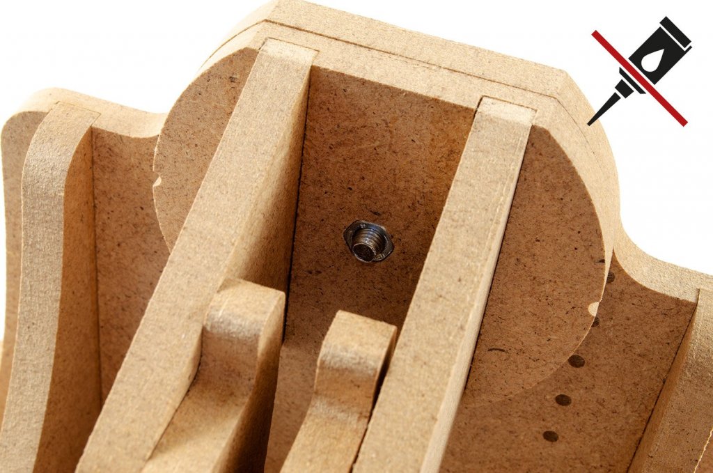
9 minutes ago, Jasseji said:
I actually have a Comment on the instructions @James H, regarding steps 7, 12 and 20.
I have placed the Nuts in the Hex-Holes same as in step 8, this way it seems easier to remove the screw if repositioning of the clamp is needed - perhaps for the holders from step 7 and 20 it is not that important, as you would only unscrew them a bit to change the angle/position but in case of the front and back holder (step 12) i would rather suggest to place the nuts in the cutouts - this screw will be more often taken out and you might damage the socket if you do it a few times.
Also you can see on this pictures, that's how Wojciech has it on his site:
Thanks for that. Depending on application, you could well be right. This is a pretty flexible system and the hardware can be changed around to accommodate the model. It's easy enough to remove and rotate these parts, thankfully. I also find it easier to drive the bolt from the socket, instead of the nuts.
- Keith Black, mtaylor, Scottish Guy and 2 others
-
5
-
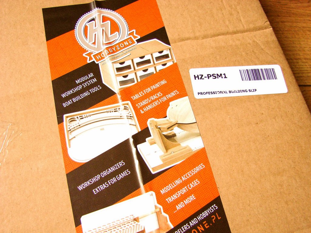
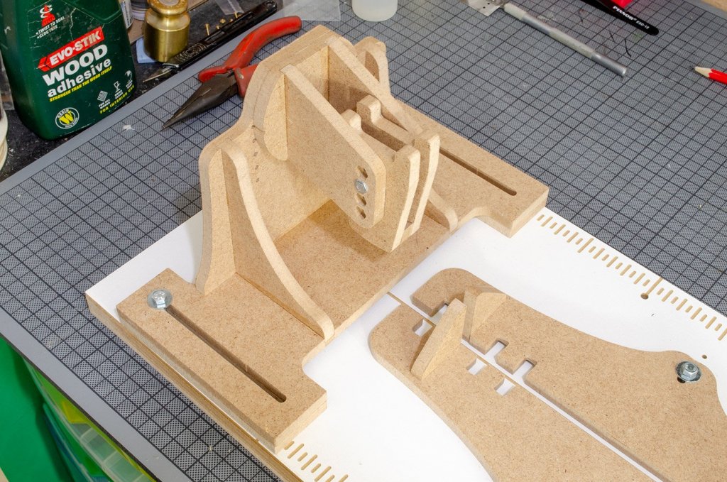
Professional Building Slip
Hobbyzone
Catalogue # HZ-PSM1
Available from Hobbyzone for £50.00
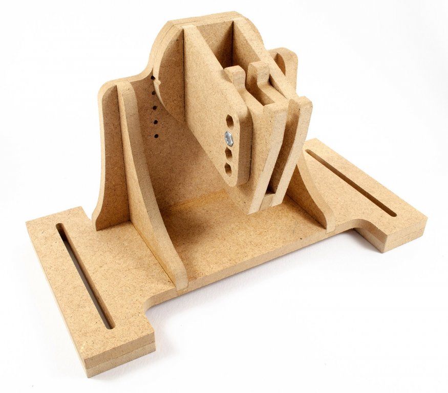
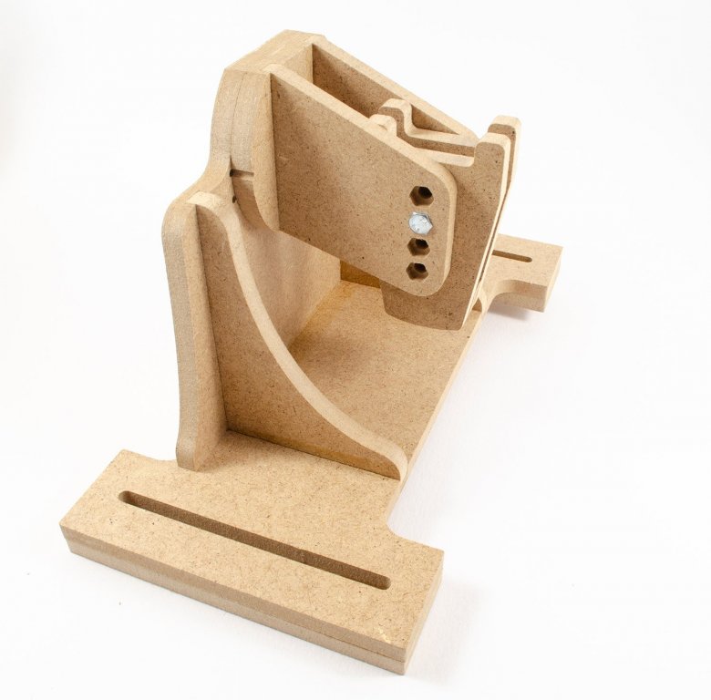
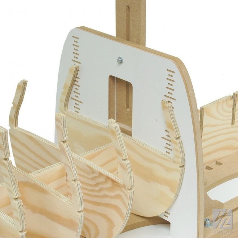
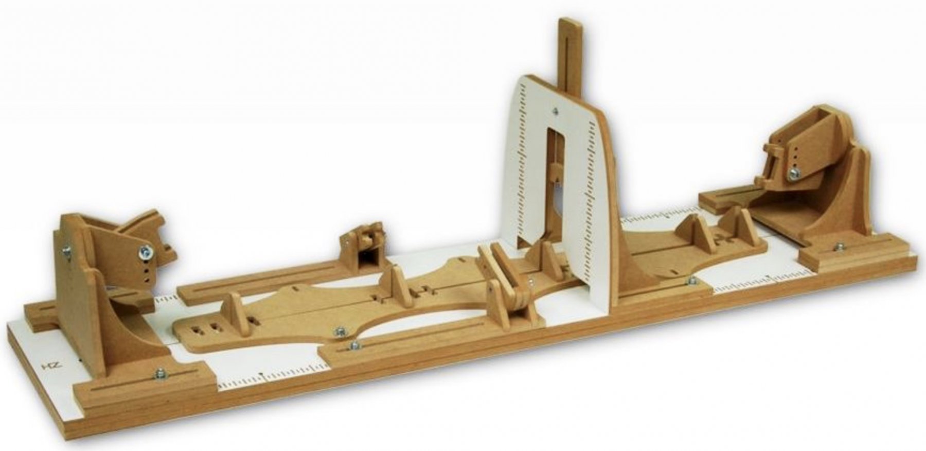
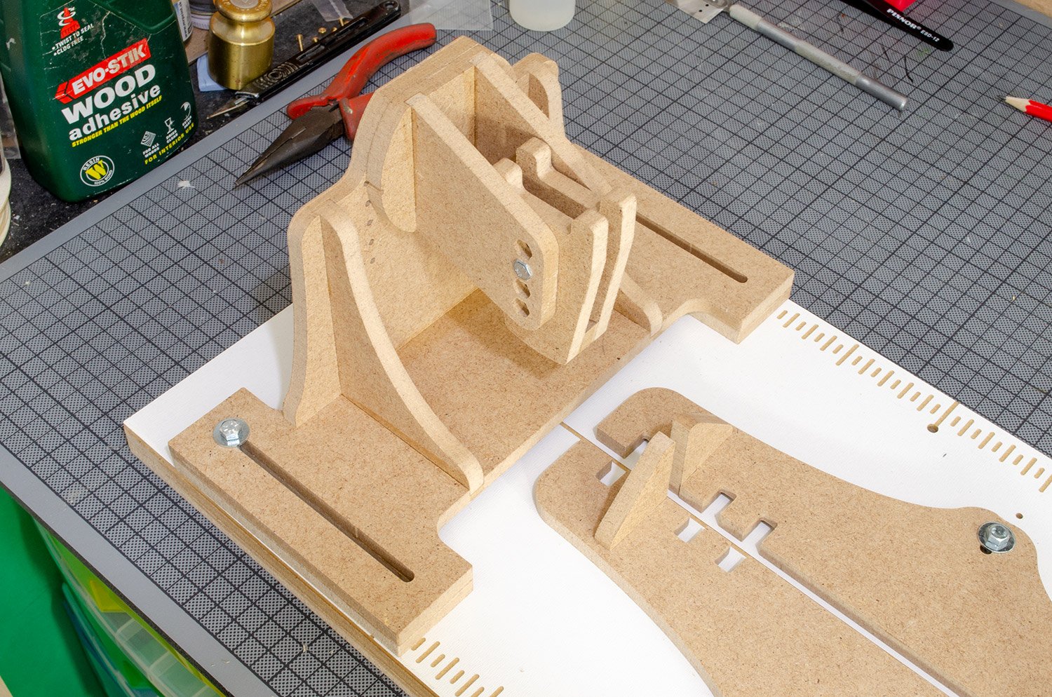
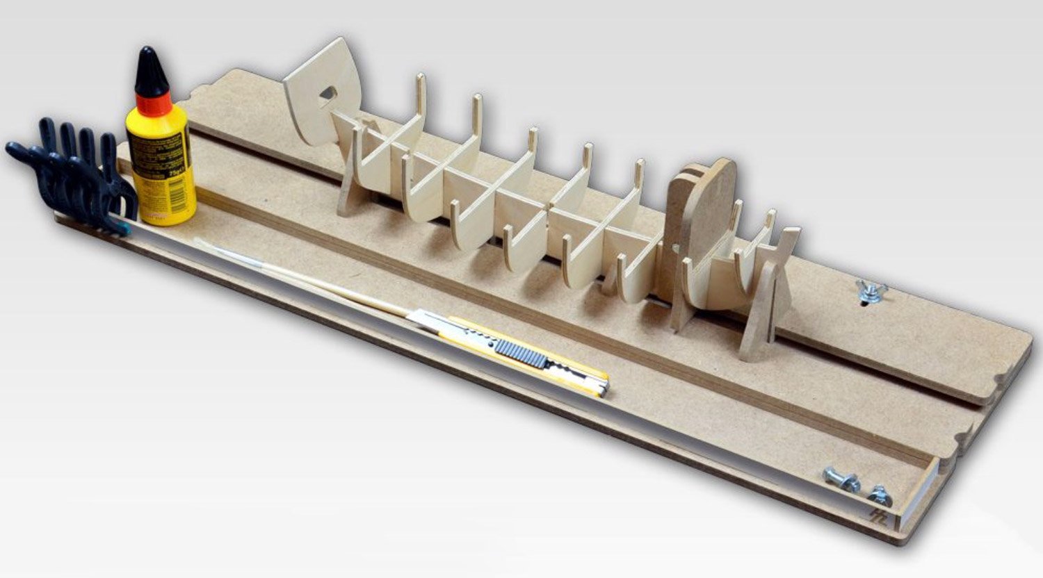
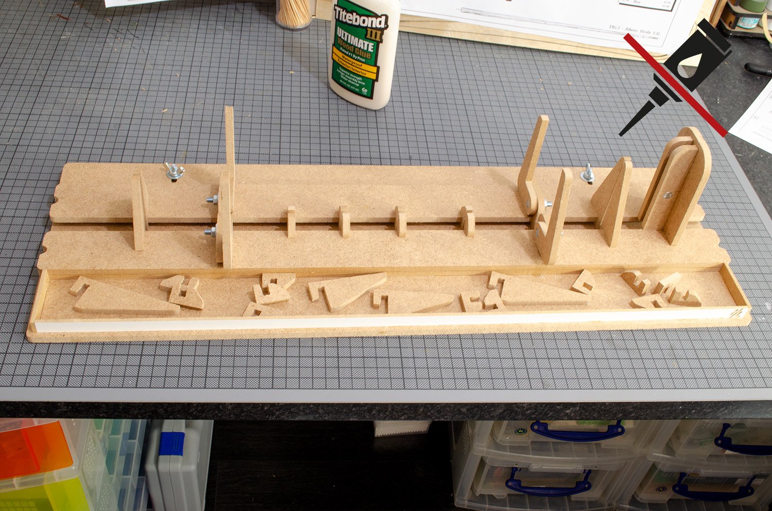
We recently took a look at Hobbyzone's Small Building Slip, catering to hull lengths of an average of 600mm to 800mm maximum, but if you want something for larger hulls and with even more flexibility, then today, we take a look at the Professional Building Slip. Hobbyzone has asked me to build this as an assembly guide for them, to help to negate any incorrect assembly which has found its way into some completed slips, and they also intend to link this guide for general reference. Some errors that customers have made pertain to parts orientation, so with this guide, we hope to show you how to successfully complete this mini-project.
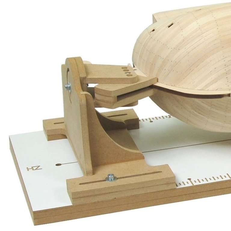
First of all, the Professional Building Slip caters to hulls up to 100cm in length, so will obviously take in many of the larger kits in our hobby, plus those impressive POF scratch builds we aspire to. This product also varies from its smaller cousin by the ability to be able to rotate a fixed hull through 360°. Of course, the slip can be used for everything from laying the keel/false keel, through to erecting the formers/bulkheads, and then to simply hold and rotate a semi-assembled hull whilst you plank and even fit out the hull at advanced stages of assembly, as well as act as a simple cradle. The completed unit has a length of 100cm, a width of 25cm and will take a keel of out to 7mm in thickness.
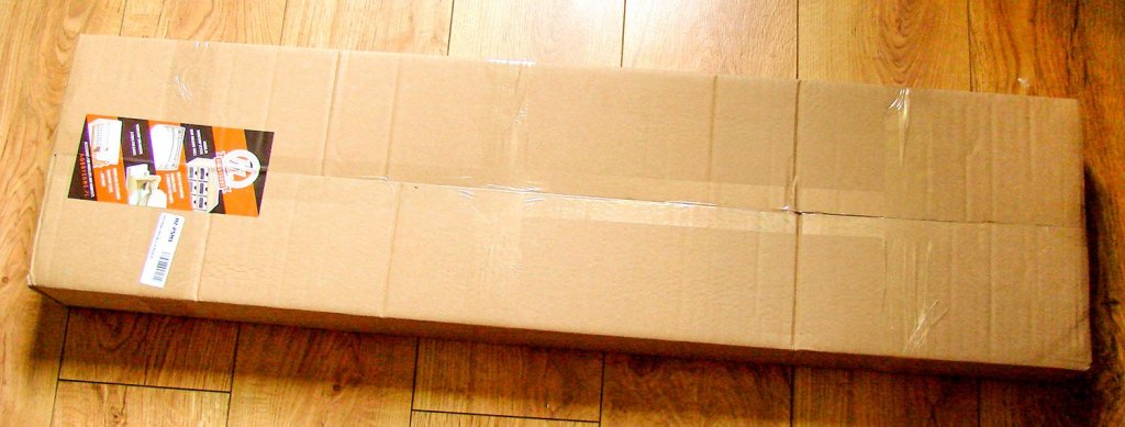
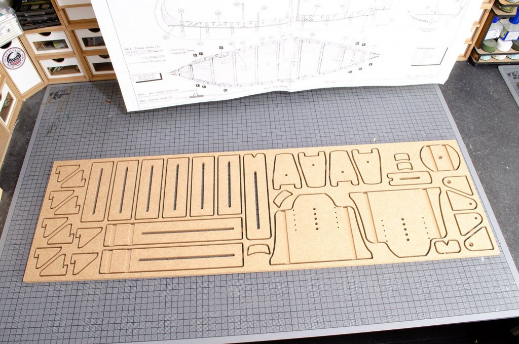
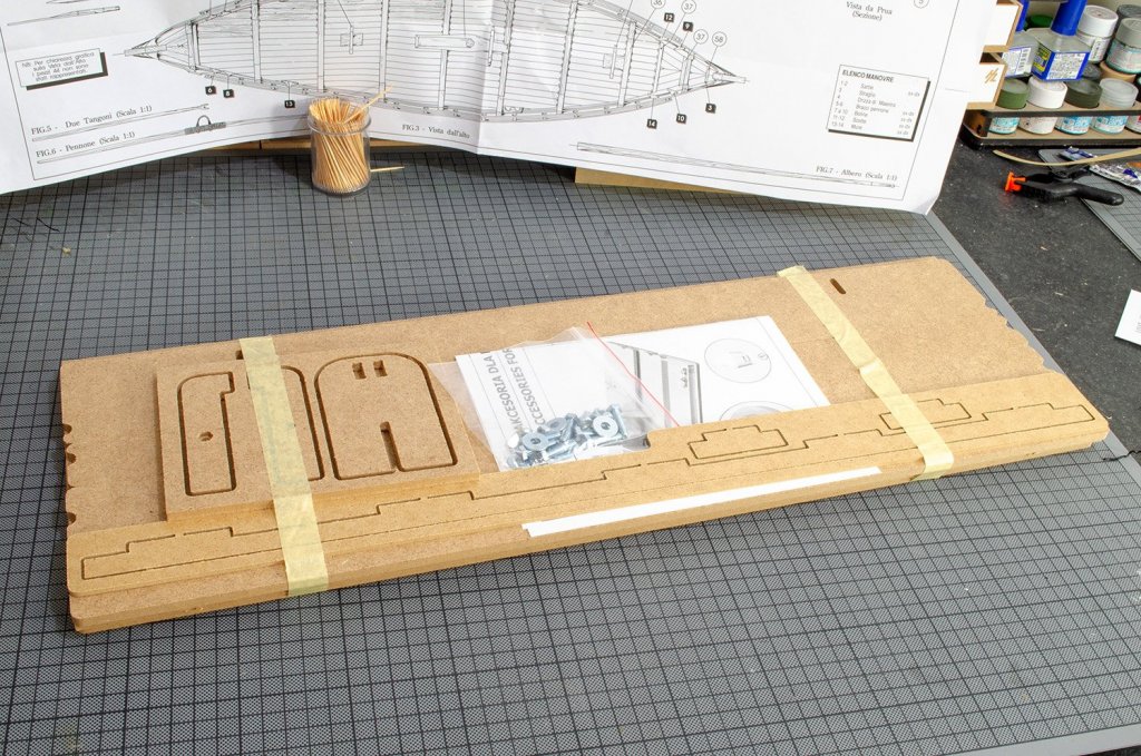
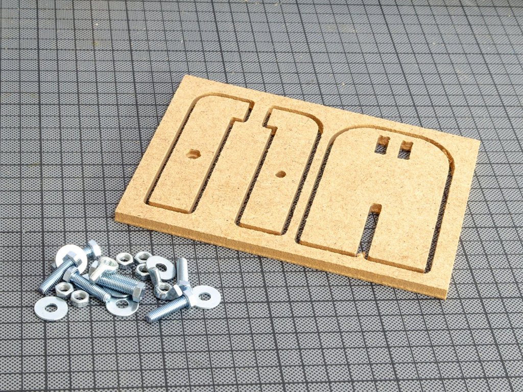
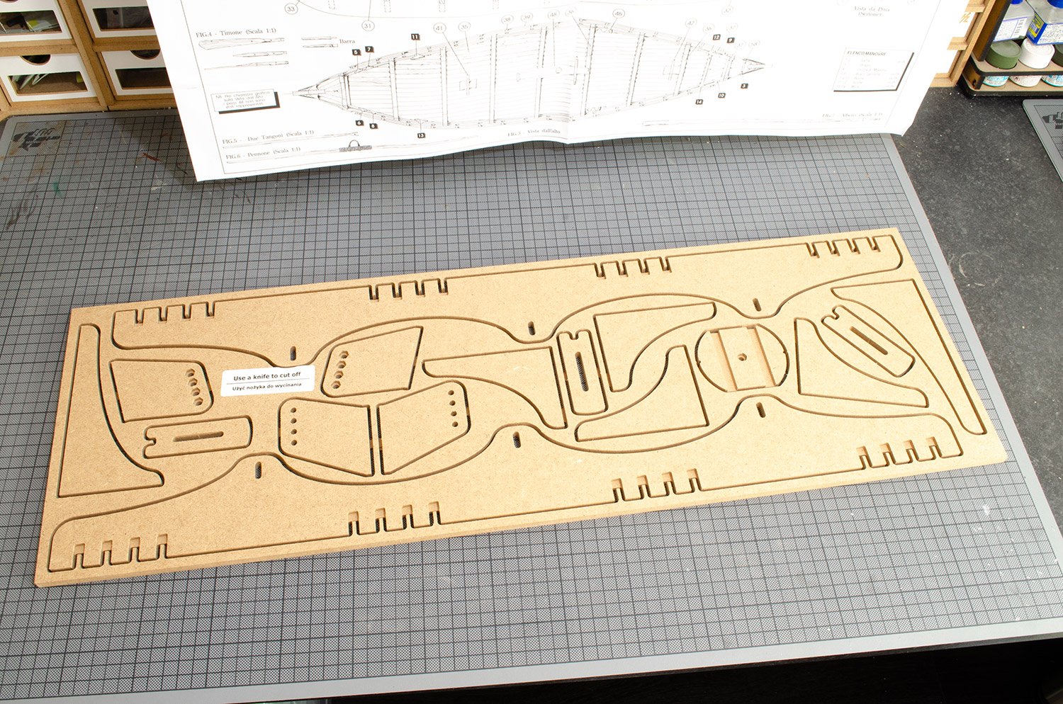
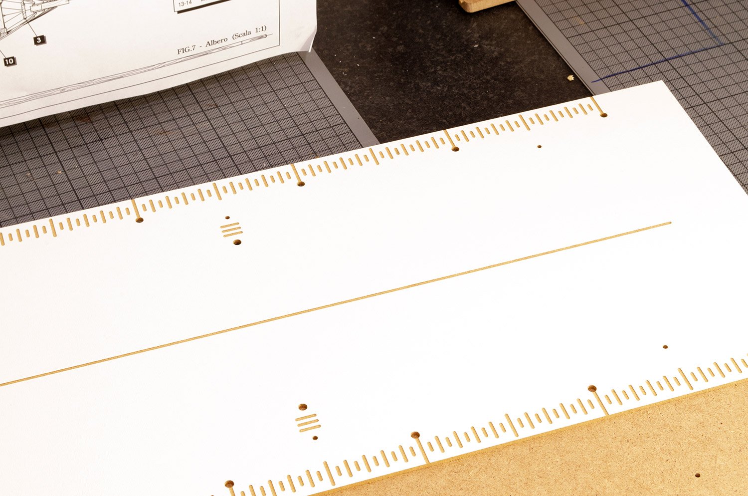
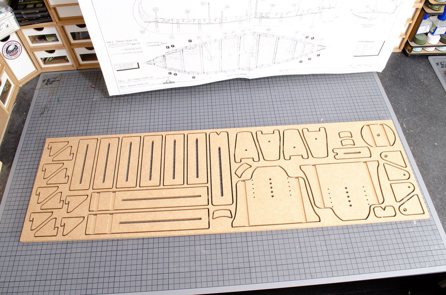
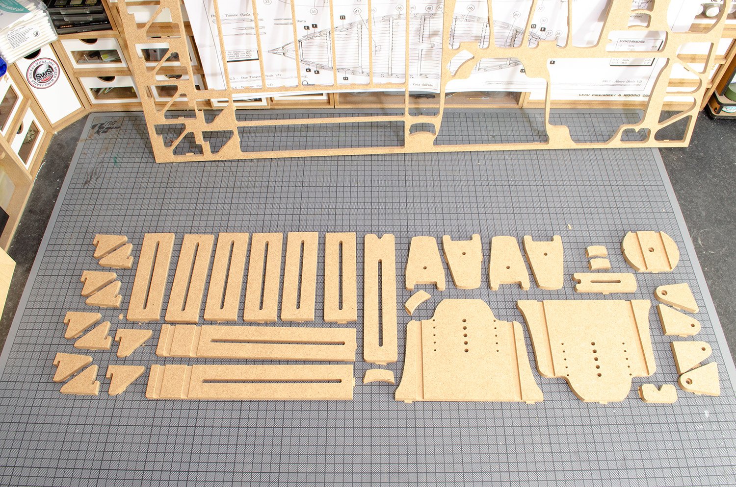
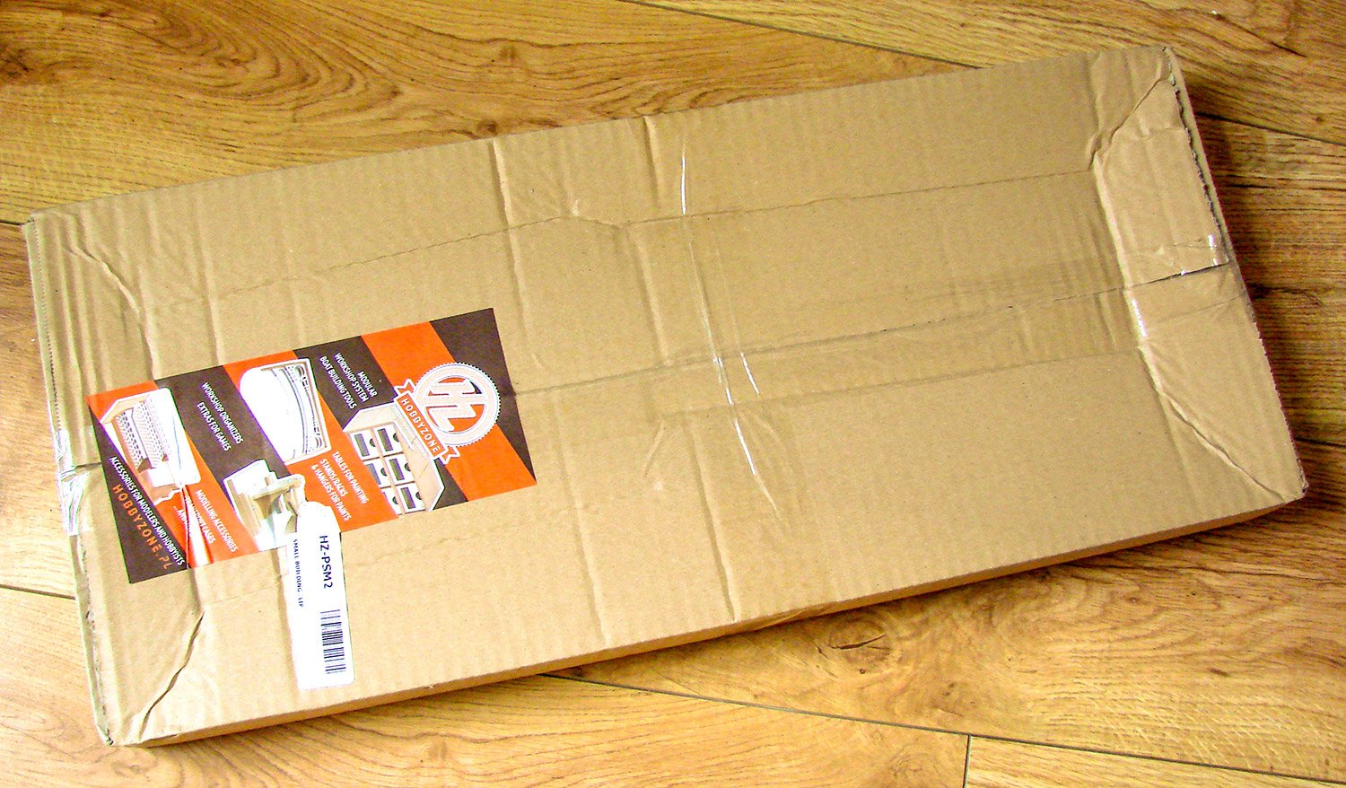
Packed into a card box, this HEAVY box has all parts within protected by many layers of bubblewrap. Construction is from MDF, with some parts being faced in plastic and engraved with the CNC router for measurements etc. A hefty hardware bag is also included. All you will need to assemble the Professional Building Slip is:
- Wood glue
- Craft knife
- Clamps
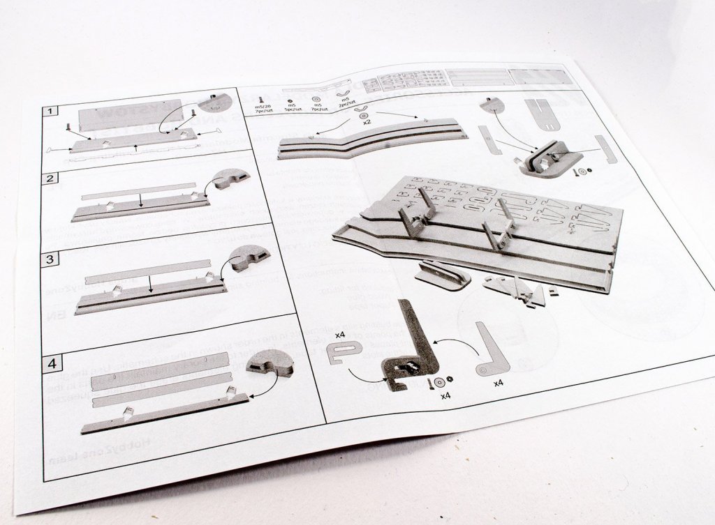
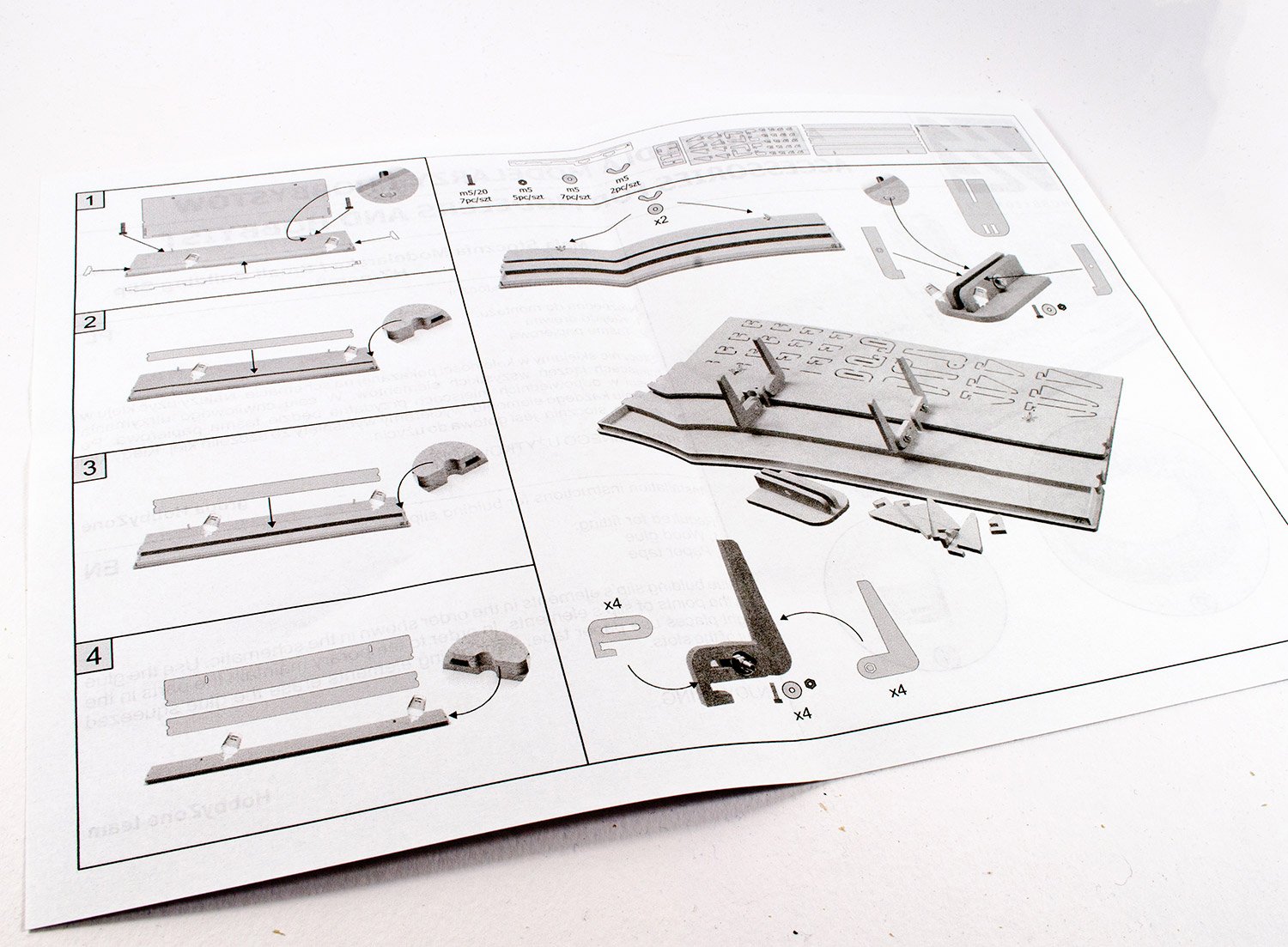
Instructions are provided on a single sheet of paper, along with an amendment slip stating the use for some included nails. We'll mention this later in the build.
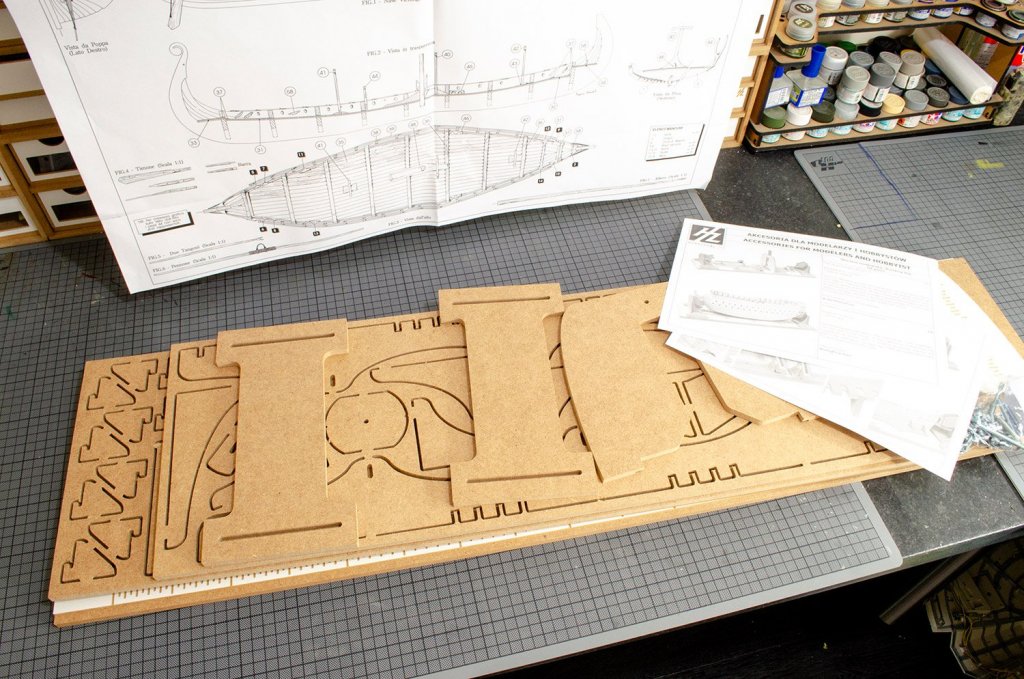
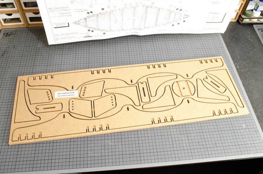
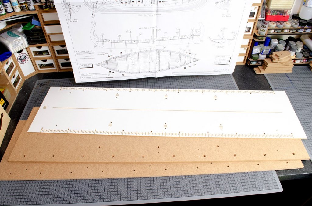
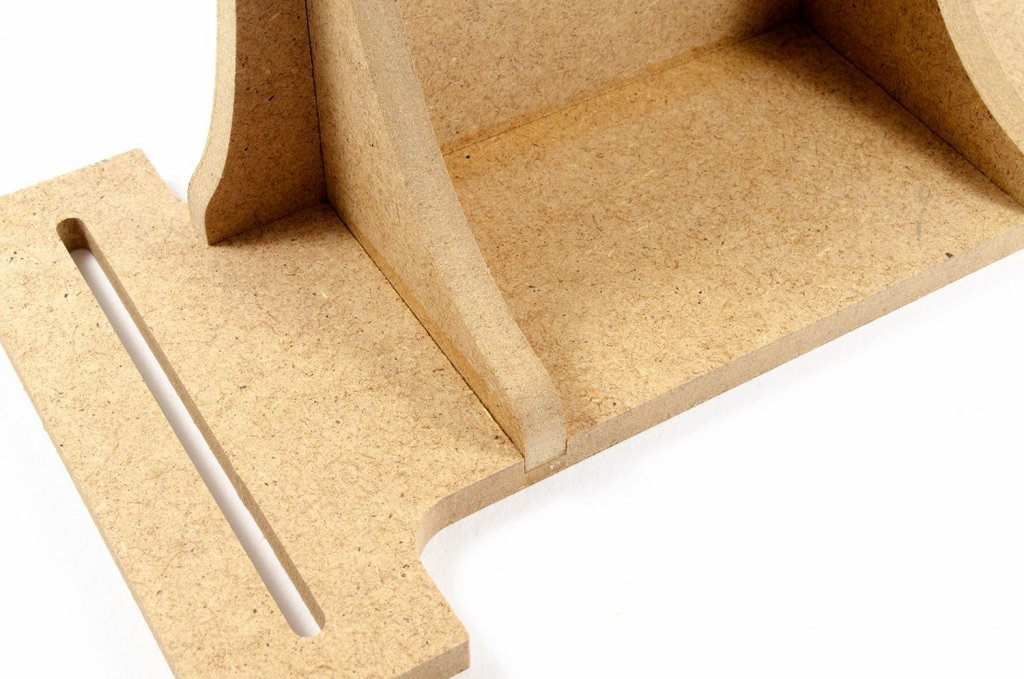
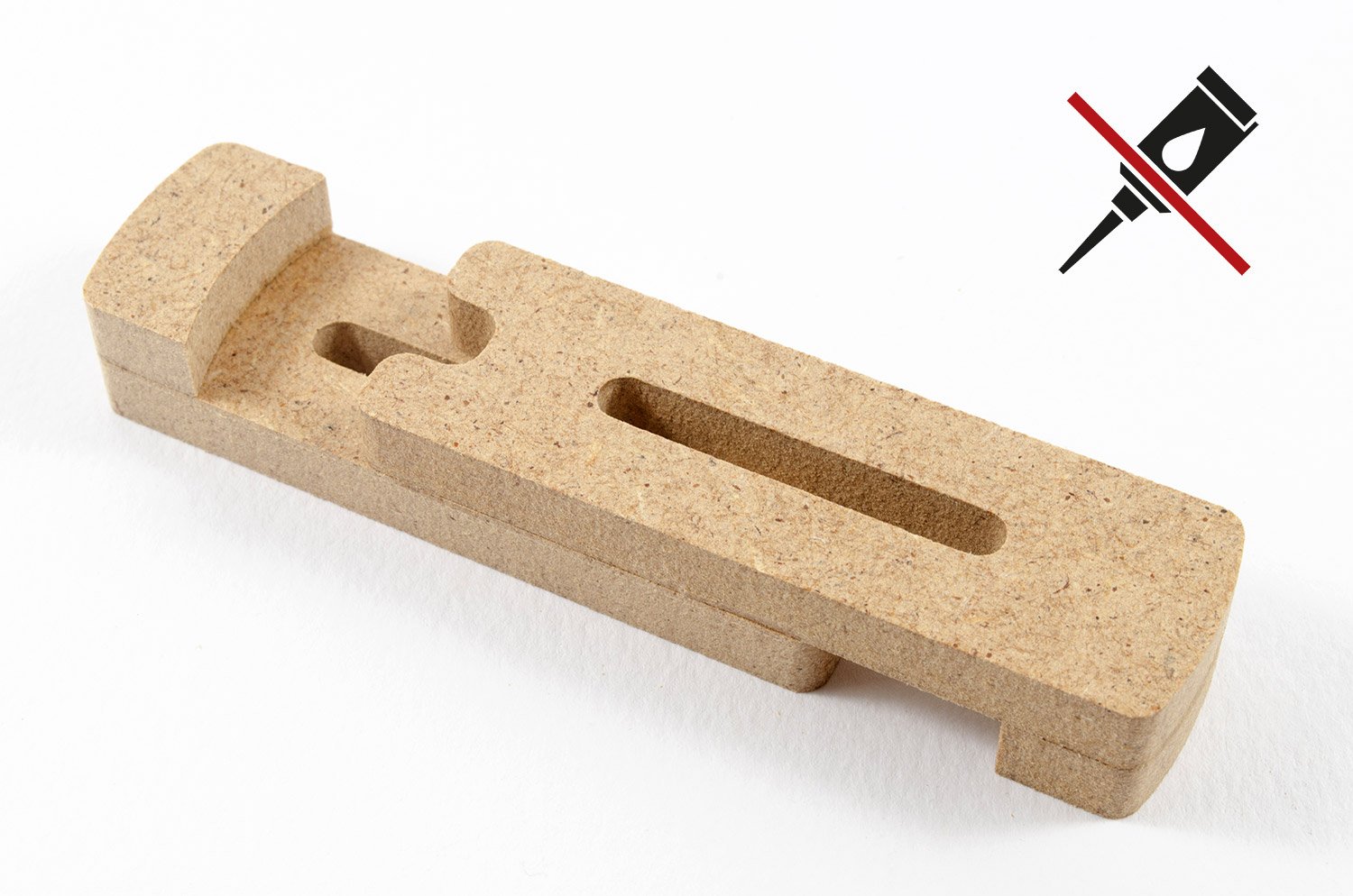
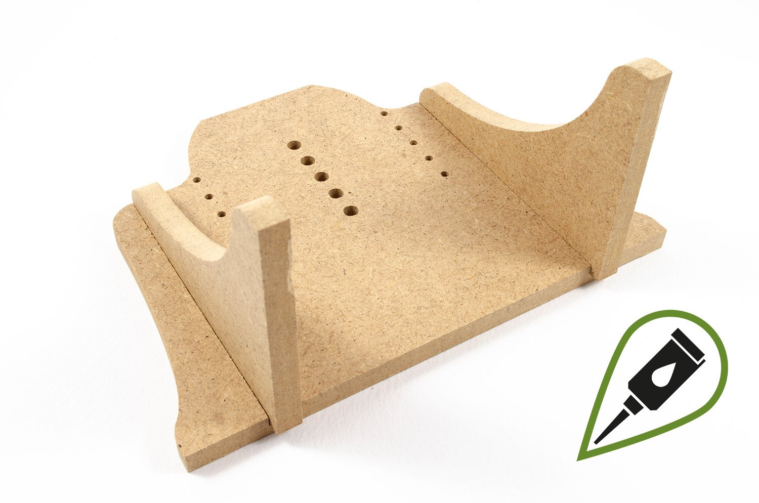
CONSTRUCTING THE PROFESSIONAL BUILDING SLIP
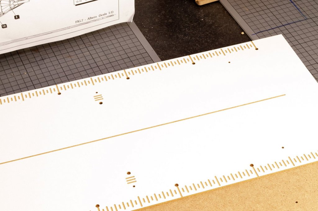
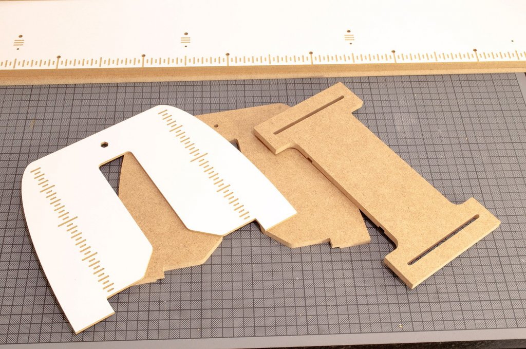
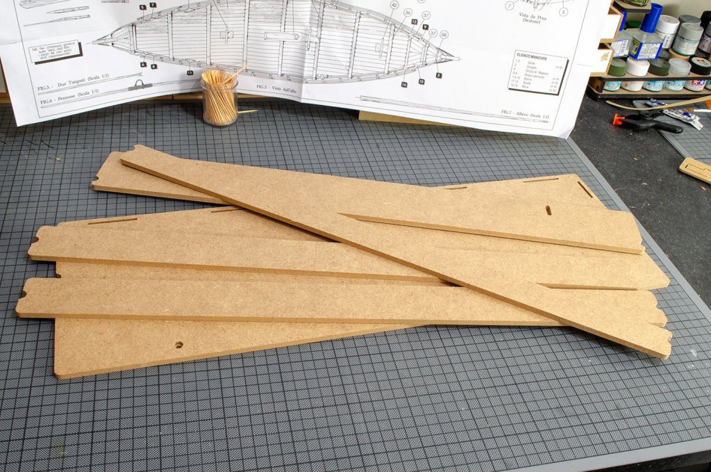
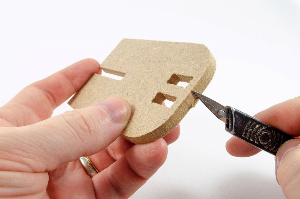
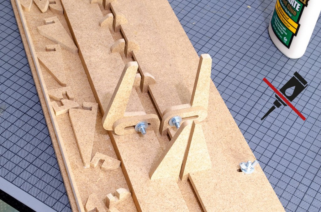
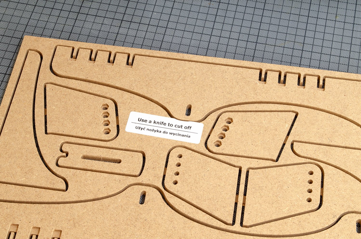
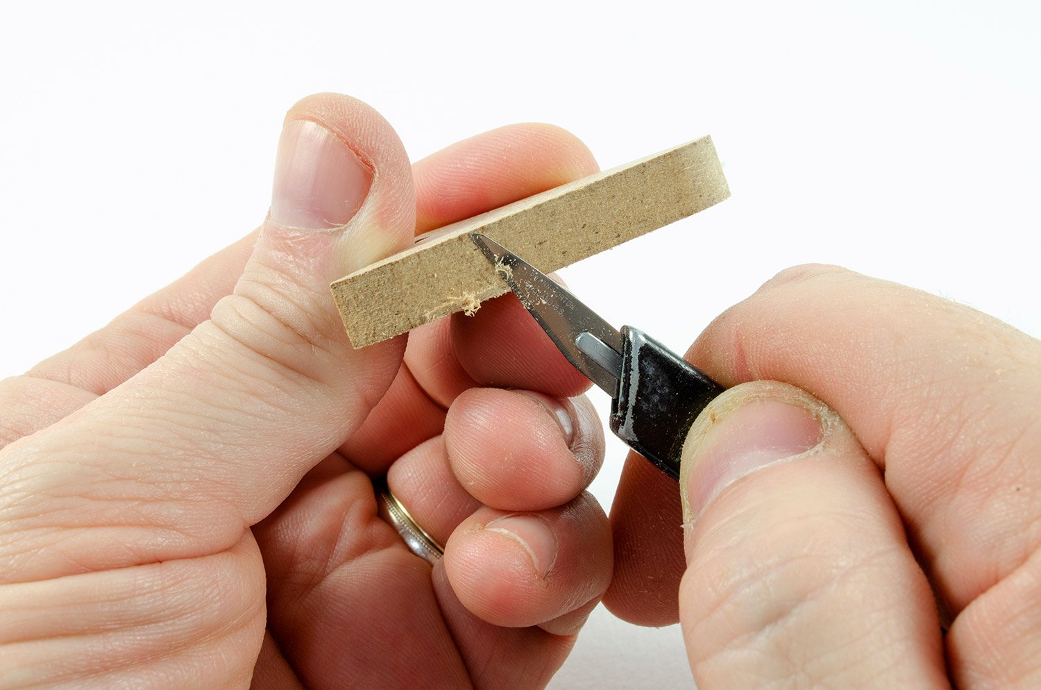
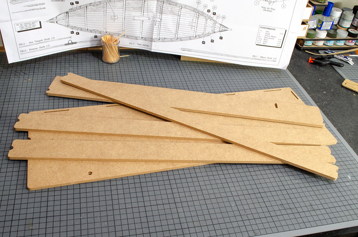
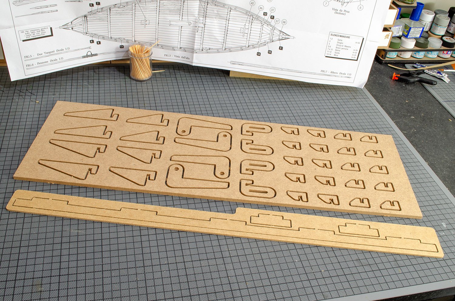
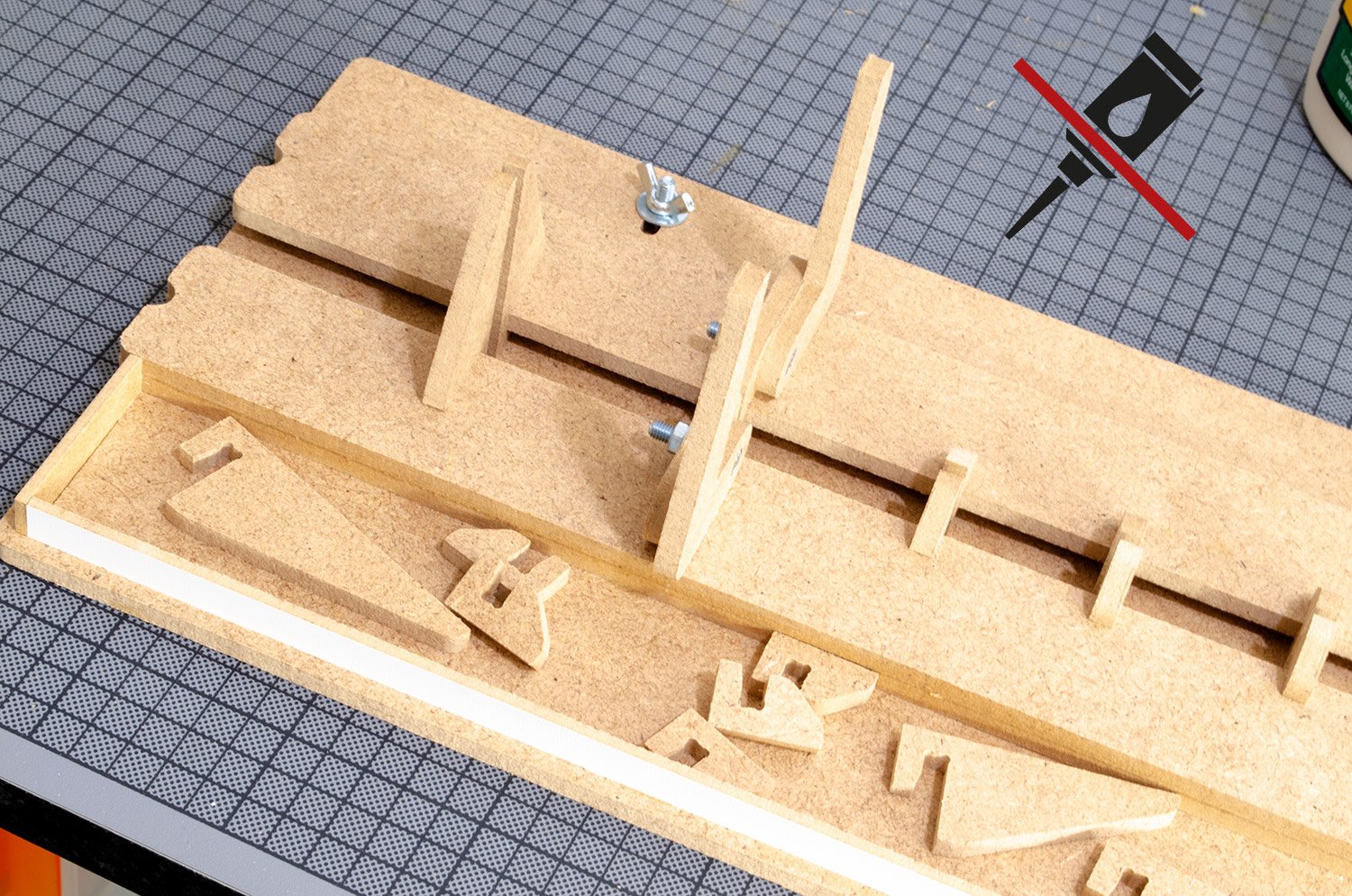
1. Before we can start to assemble this project, all parts need to be released from the CNC-routed sheets. A couple of shallow tags are all that connect the parts to their sheets, and these can simply be cut through with a regular craft knife.


2. Once all parts are released, remove any traces of the MDF tags that held them onto the frames. A craft knife is all that is required for this.

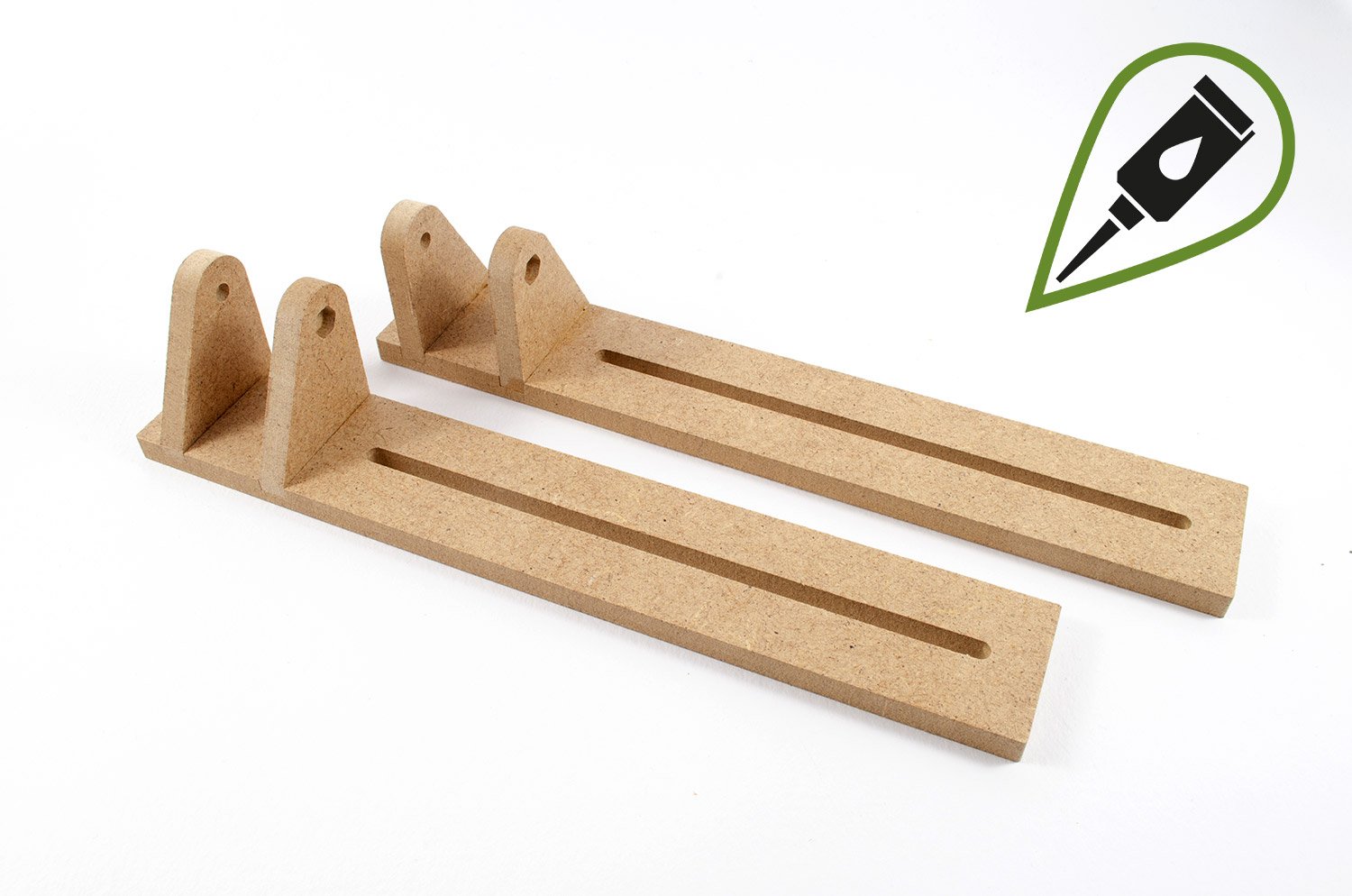
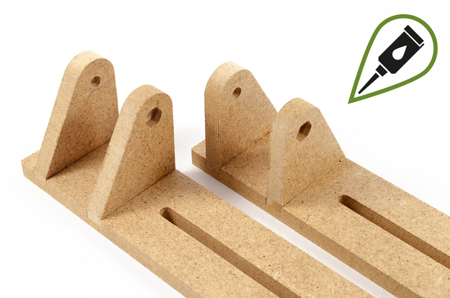
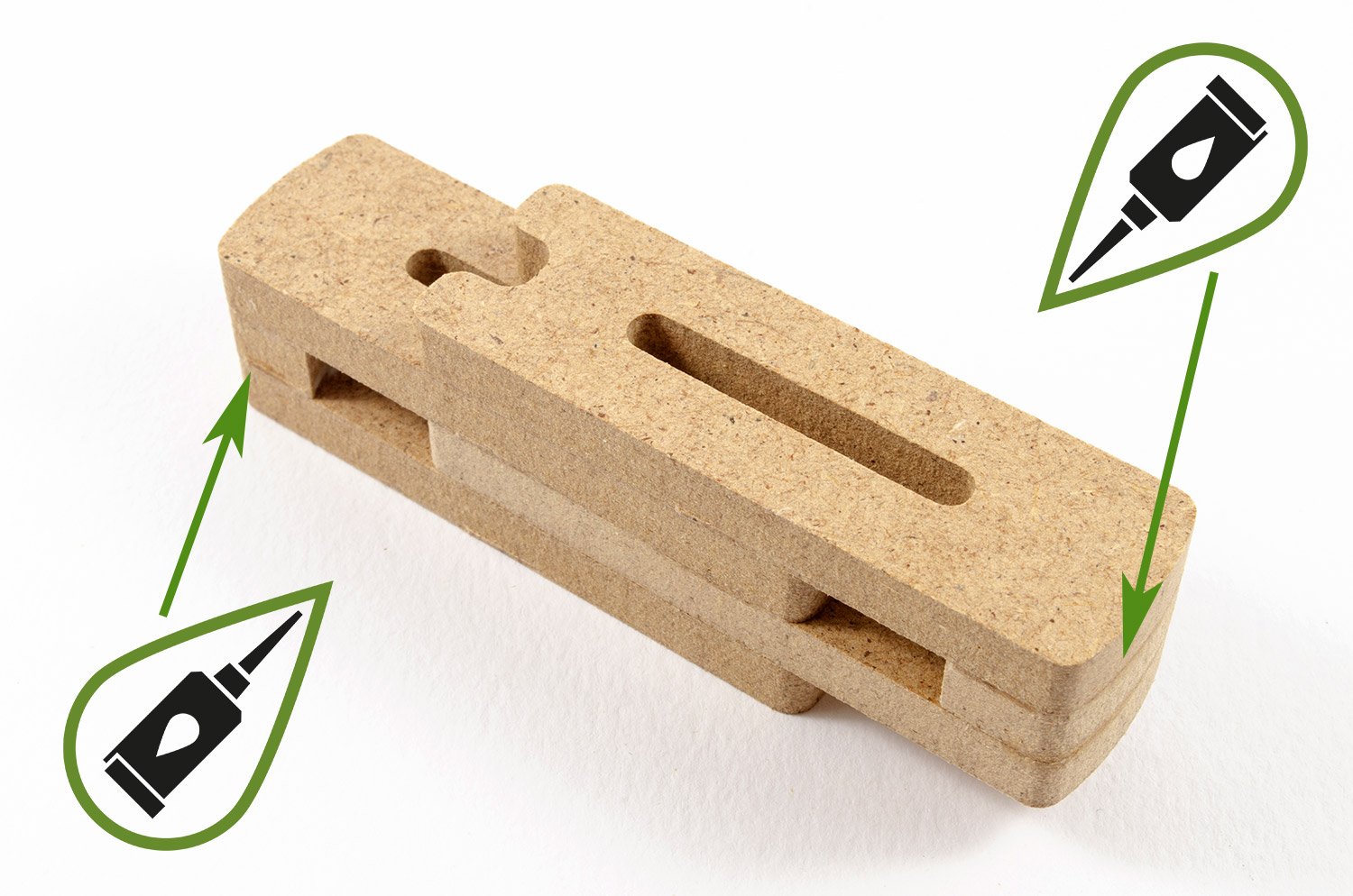
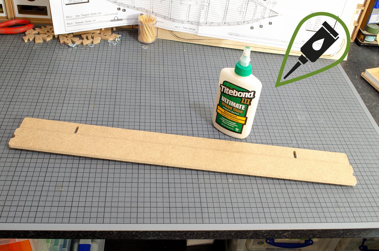
3. I now construct the guide bars that sit either side of the slip, using Titebond III glue to secure. Please note the orientation of the vertical parts, and the hex nut head position. These items are mirrored.

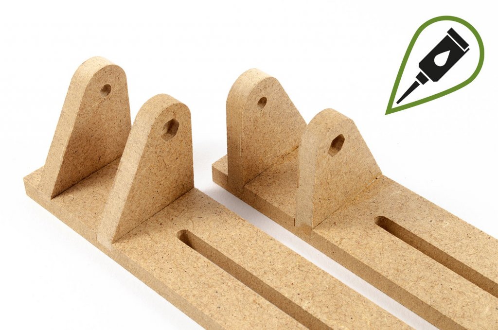
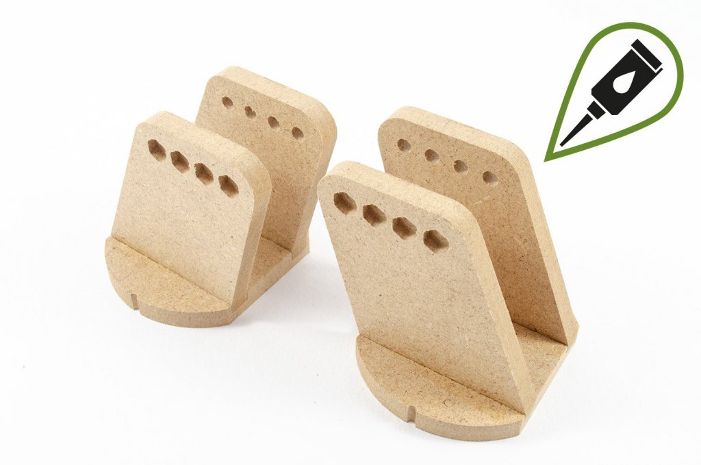
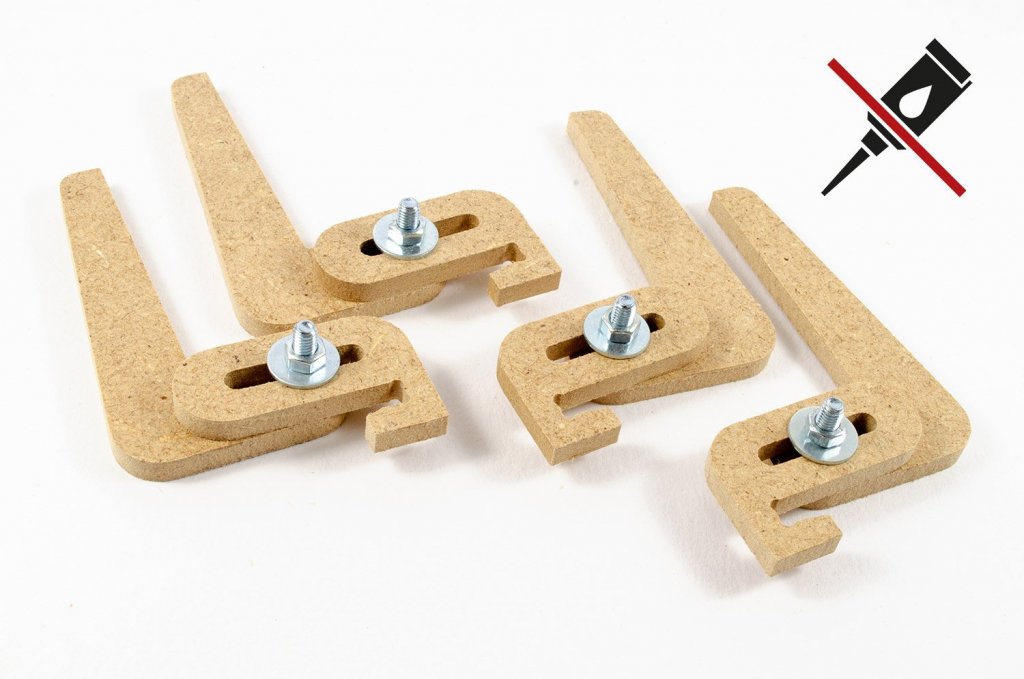
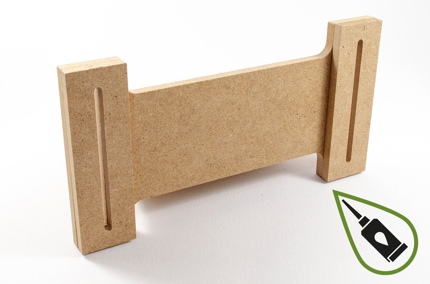
4. Each of these guide bars will hold a clamp that will grip the various formers/bulkheads of your model. To begin their construction, I glue the following items together.
5. When these had set, I sat them on top of each other. DO NOT GLUE!

6. NOW, I may glue the other halves of the clamps into place. Sitting the two sections together merely ensures that the clamp faces are parallel to each other...nothing more.

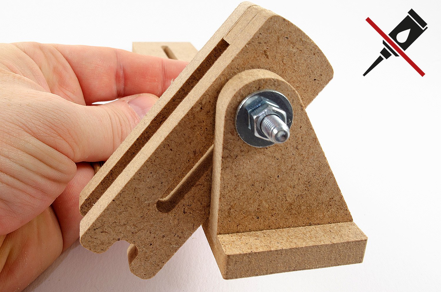
7. With everything fully dry, the clamps are fitted to the guide bars that I previously made, using the nuts, bolts and washers in the hardware pack. Again, not the orientation of the clamps in the guide bars, and that their positions are mirrored.

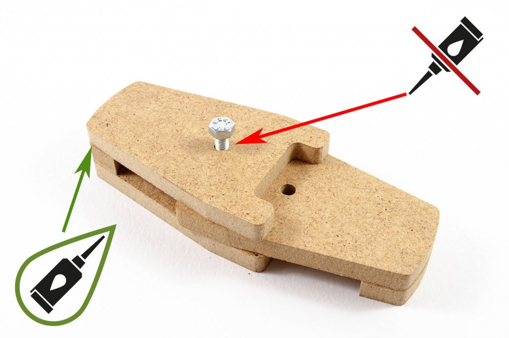
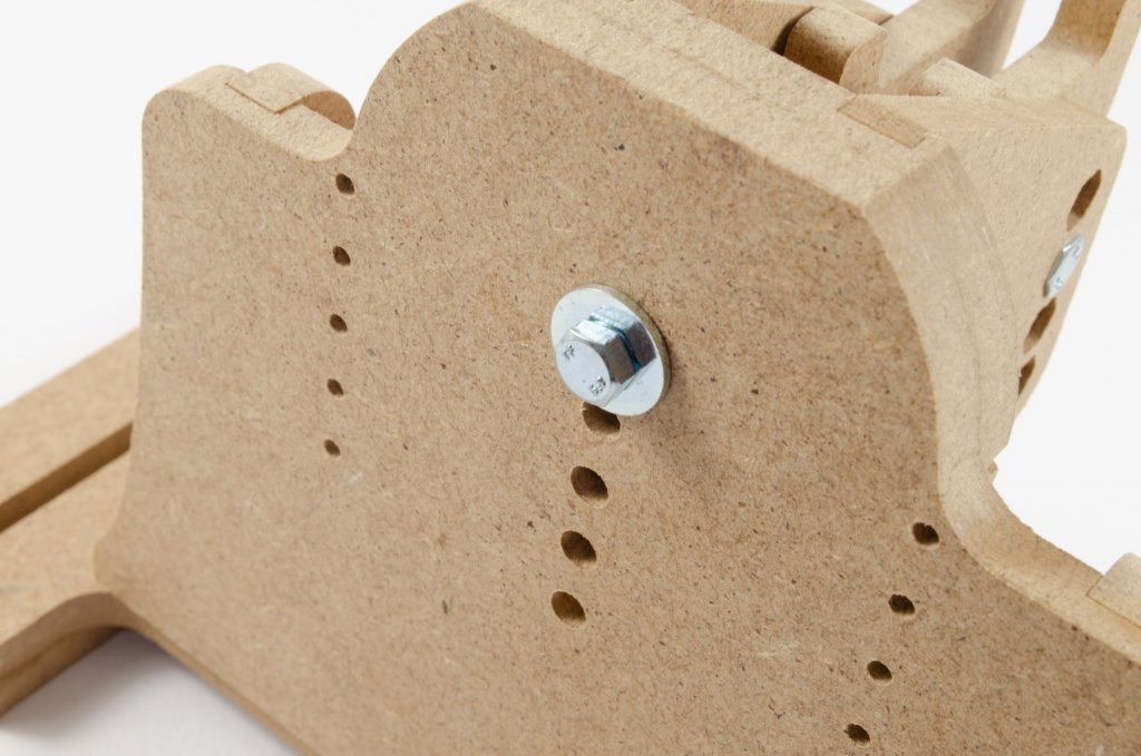
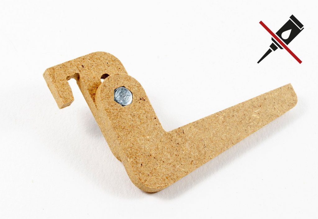
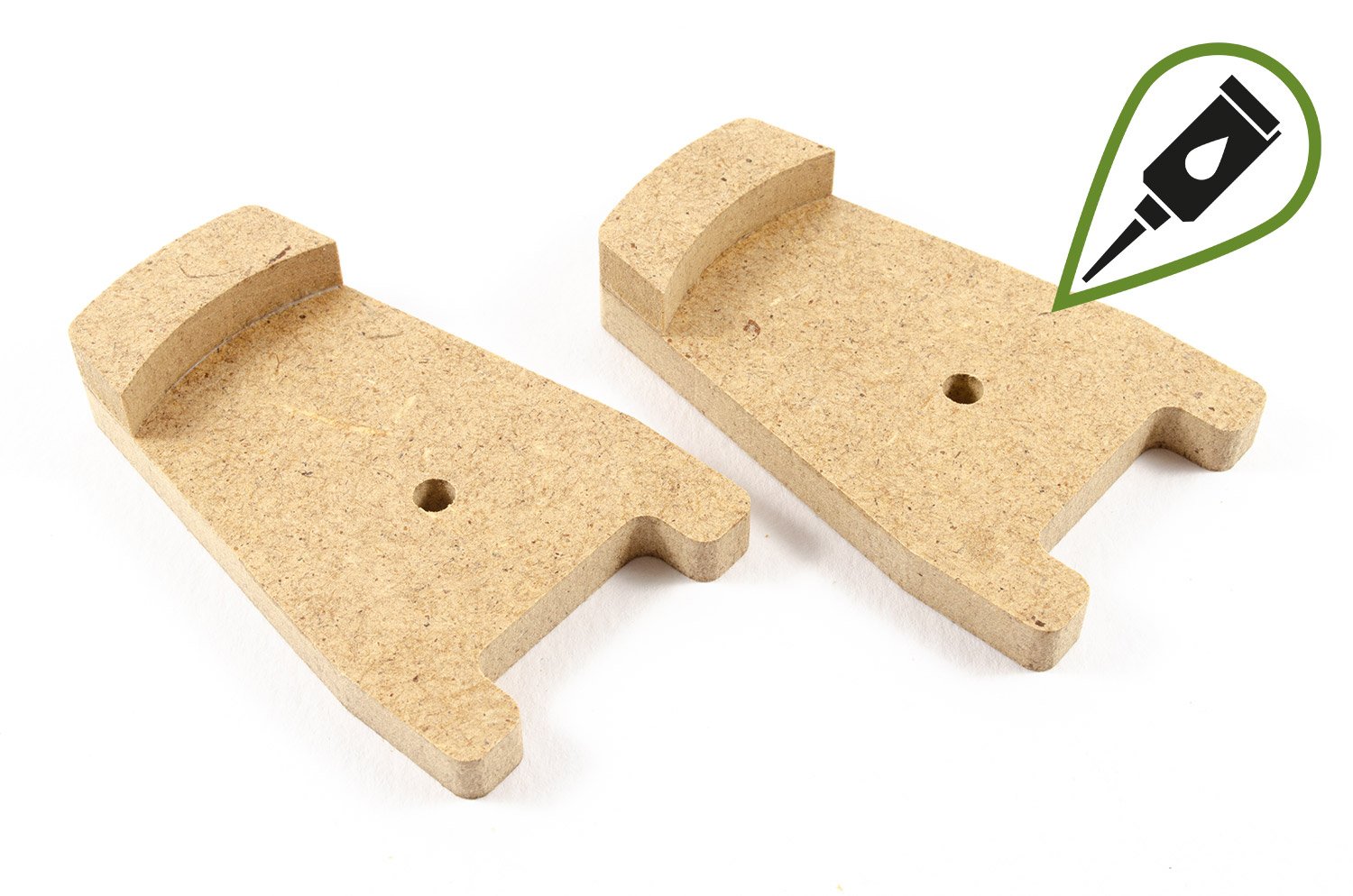
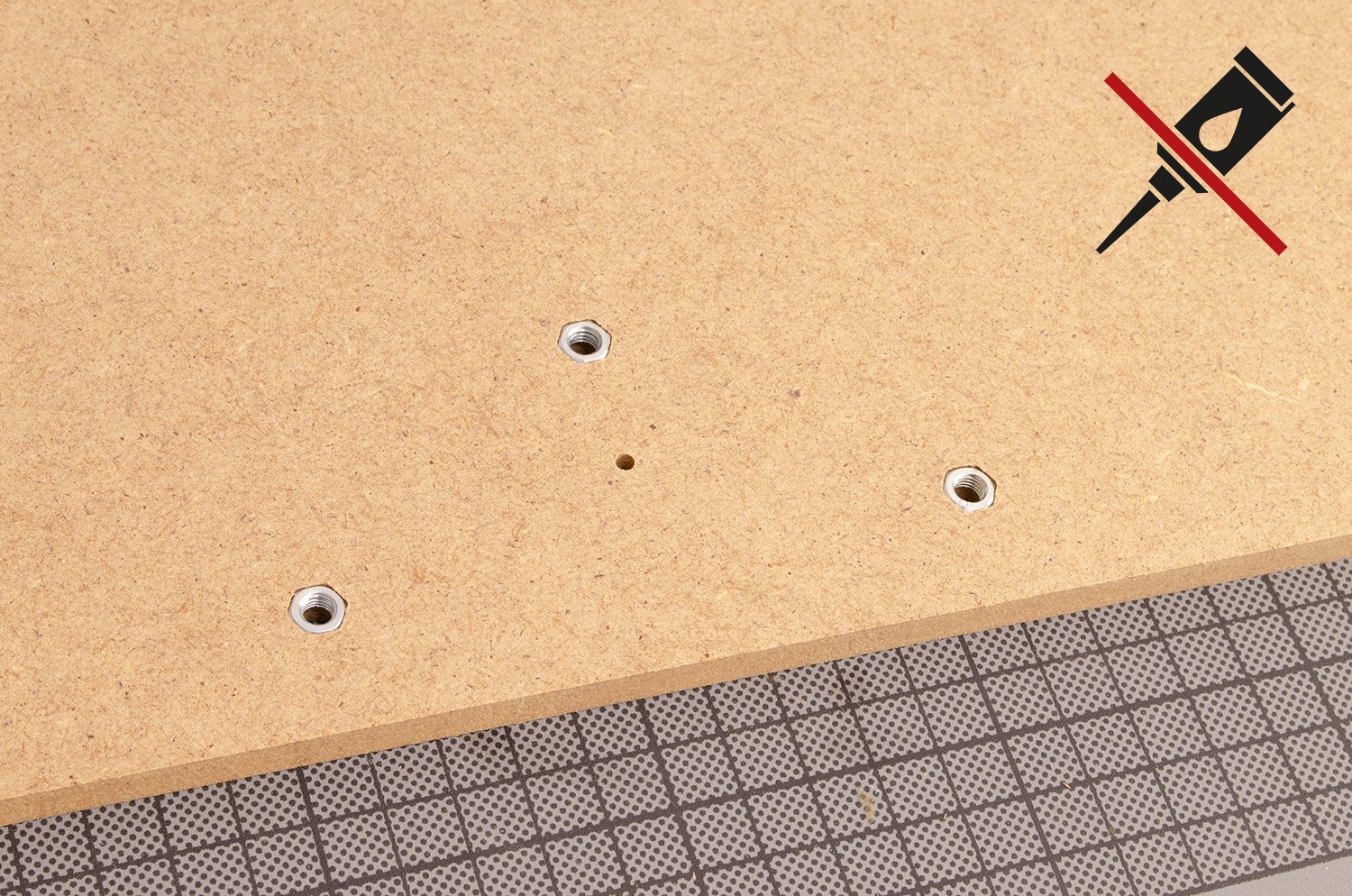
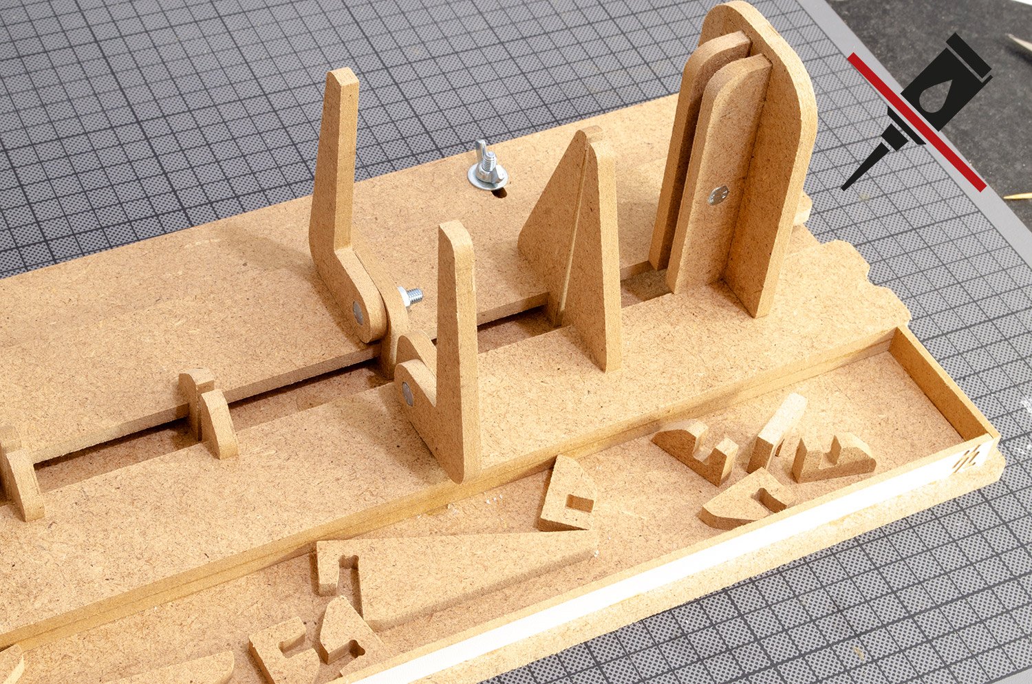
8. Now I will construct the keel clamp holders that secure to the vertical platforms at each side of the Professional Building Slip. Here, we just push the two nuts firmly into position on the backplates.
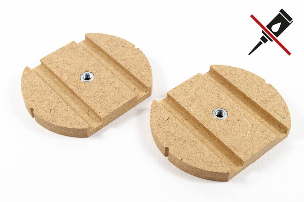
9. Using wood glue, attach the keel clamp holder faces to the backplates. Please note the orientation with regard to the hex-head positions, and ensure that everything is square.
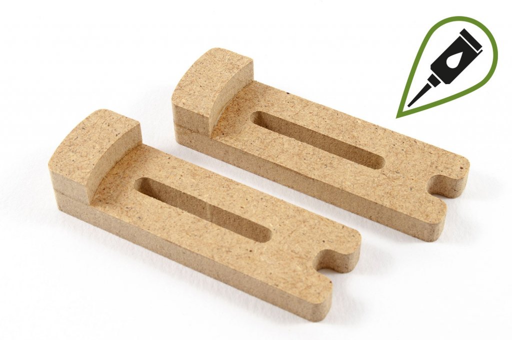
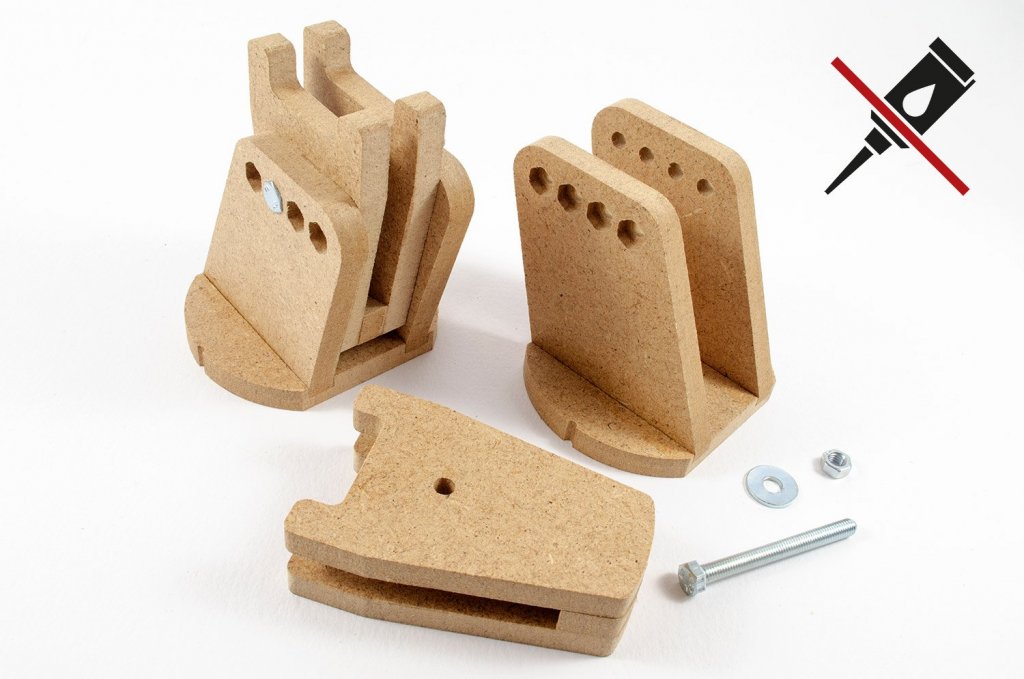
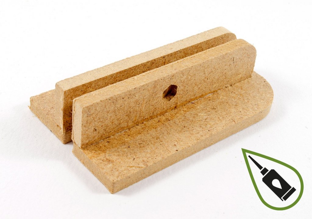
10. Now we can construct the keel clamps, in exactly the same way that we made them for the guide bars in the earlier stages. Firstly, glue the parts you see together, using wood glue.

11. Glue the opposite side to the two clamps, and use a bolt to ensure that the holes are aligned. Remember, these two keel clamps in the photo are only sat on top of each other to ensure that the jaws are equidistant. Do not glue them together, of course!
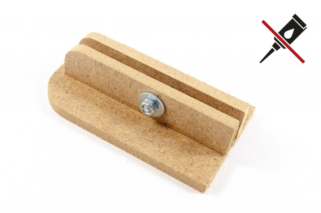
12. When all parts are set, fit the keel clamps to the clamp holders, using the nuts, bolts and washers. Please note that the positions of the bolts can be changed to suit the model you are building.
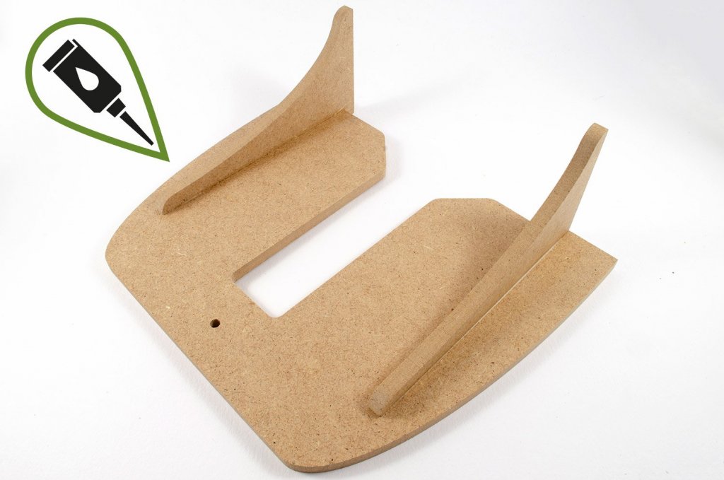
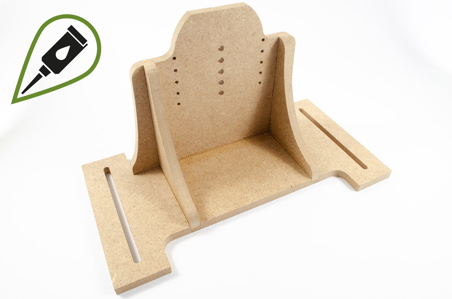
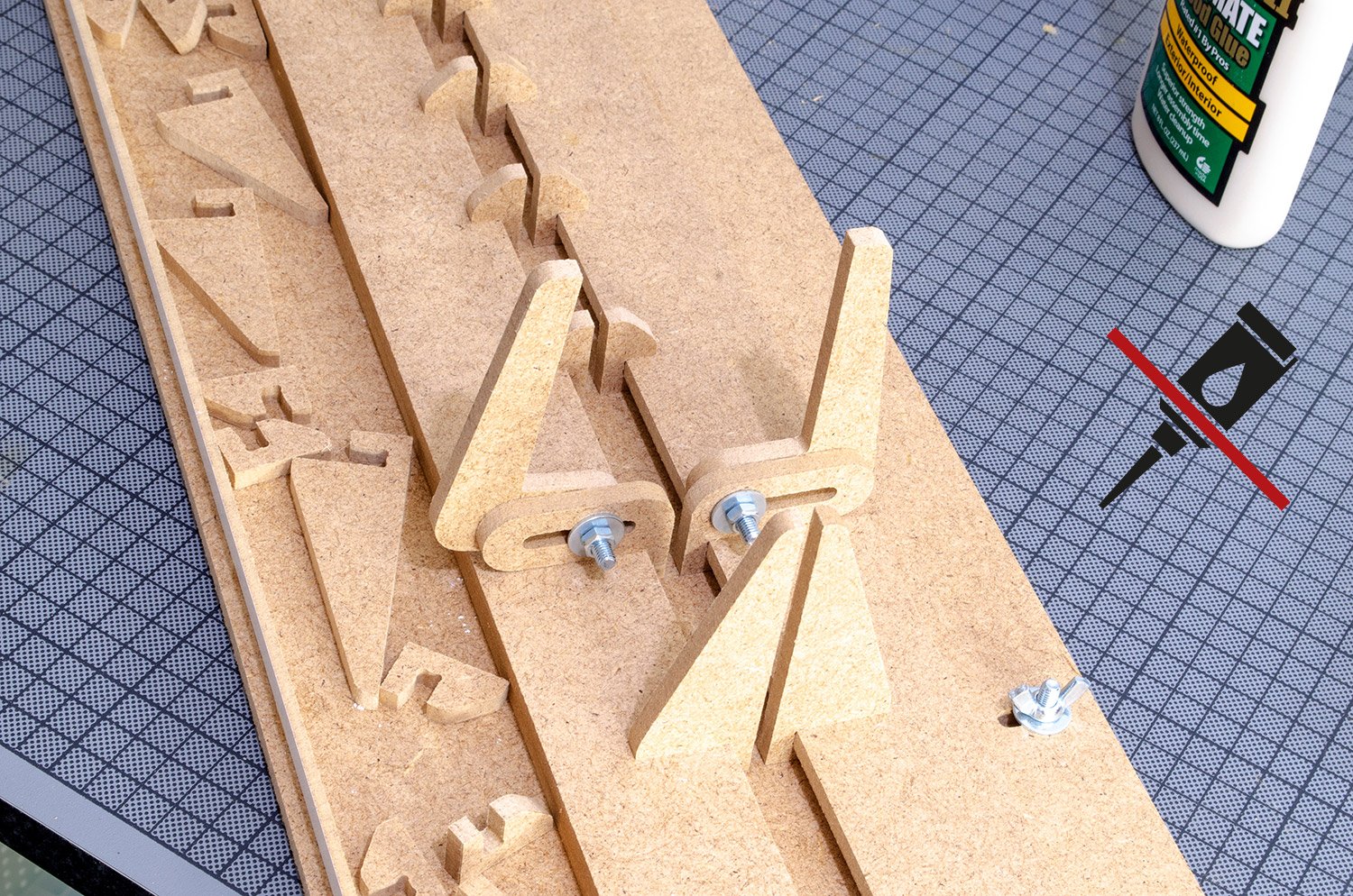
13. Each of the keel clamps we have just built, is secured to a moveable guide that sit at either side of the Professional Building Slip. To build the guides, I first glue the two supports in position on each of the guide faces.

14. Now, NOTING ORIENTATION of the baseplate, each in turn is glued to the vertical face and left to thoroughly set.

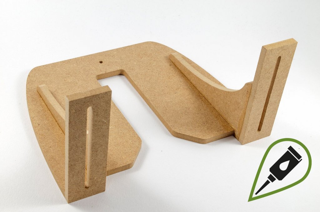
15. Glue the feet to the underside of each of the moveable guides.

16. Using the supplied nuts and bolts, fasten the keep clamps to the moveable guides.
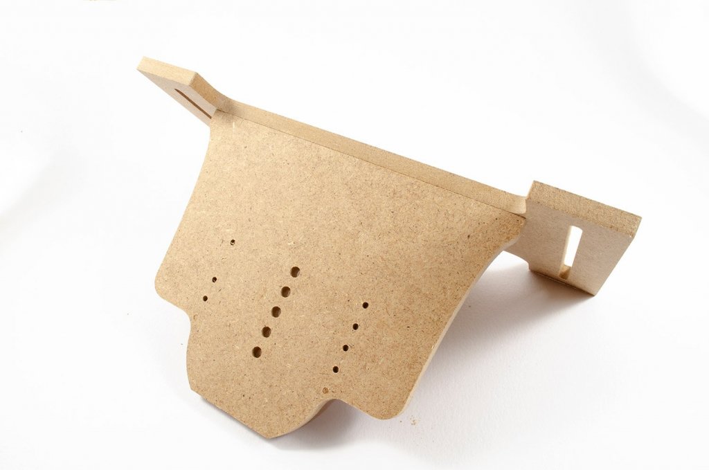
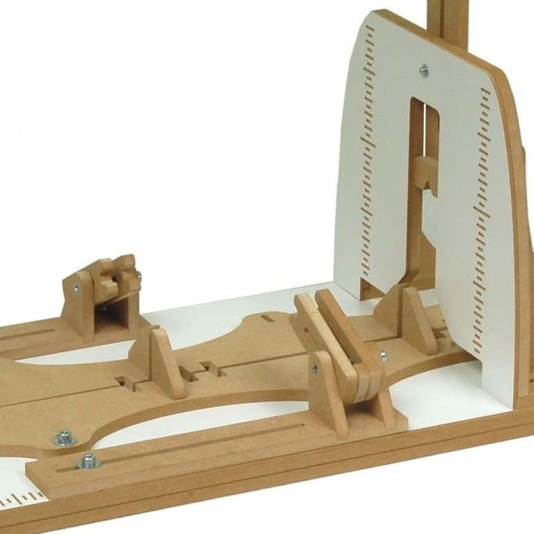
17. We can now build the vertical face which helps us to ensure the model's bulkheads and frames are vertical and even in height on both sides. Firstly, glue the supports to the vertical face.
18. Now glue the feet.
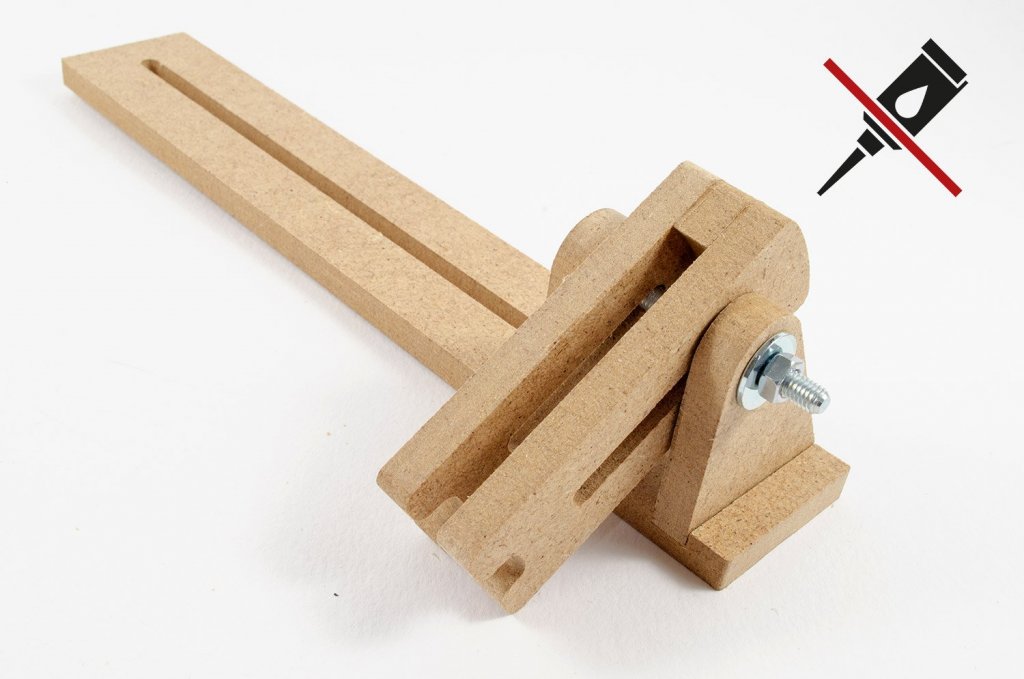
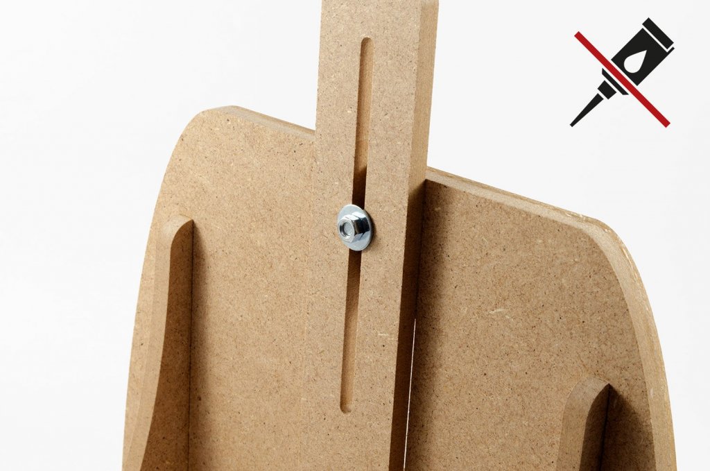
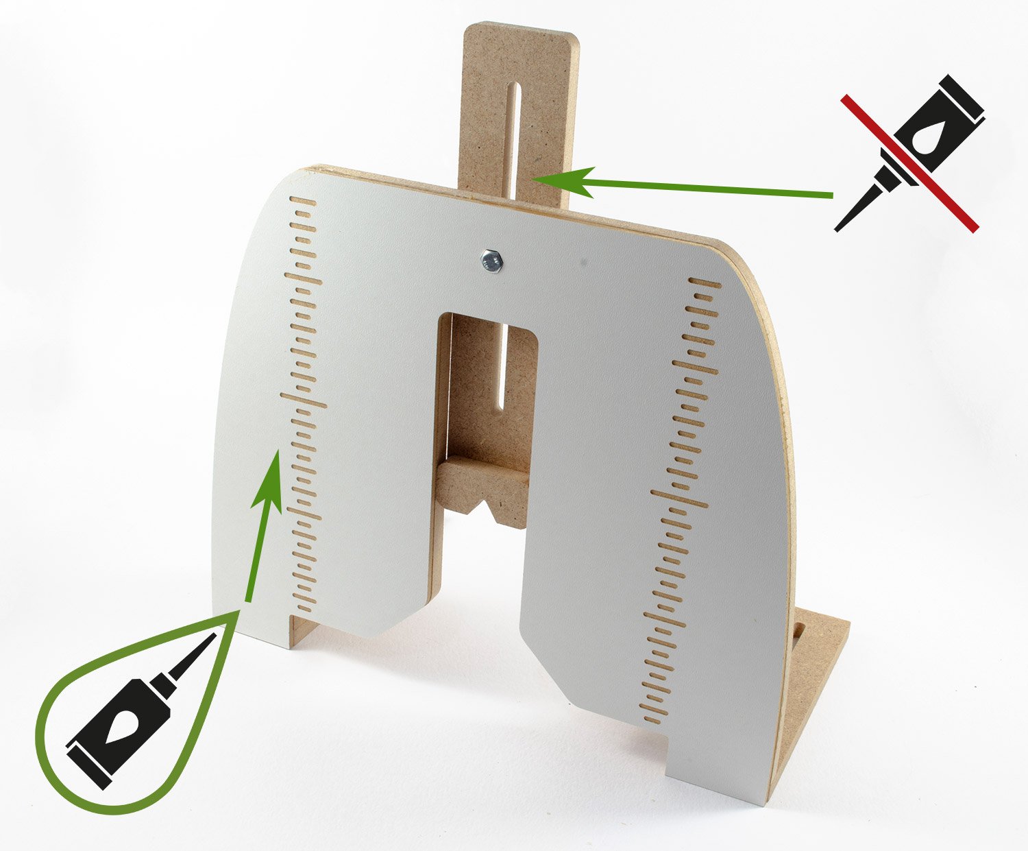
19. At this point, I decide to glue the parts together for the guide which slides up and down this vertical plate.

20. Now I can bring this guide together with the main assembly and fit it with the nut and bolt, so it may be adjusted. I also glue the main white face to the vertical guide plate.

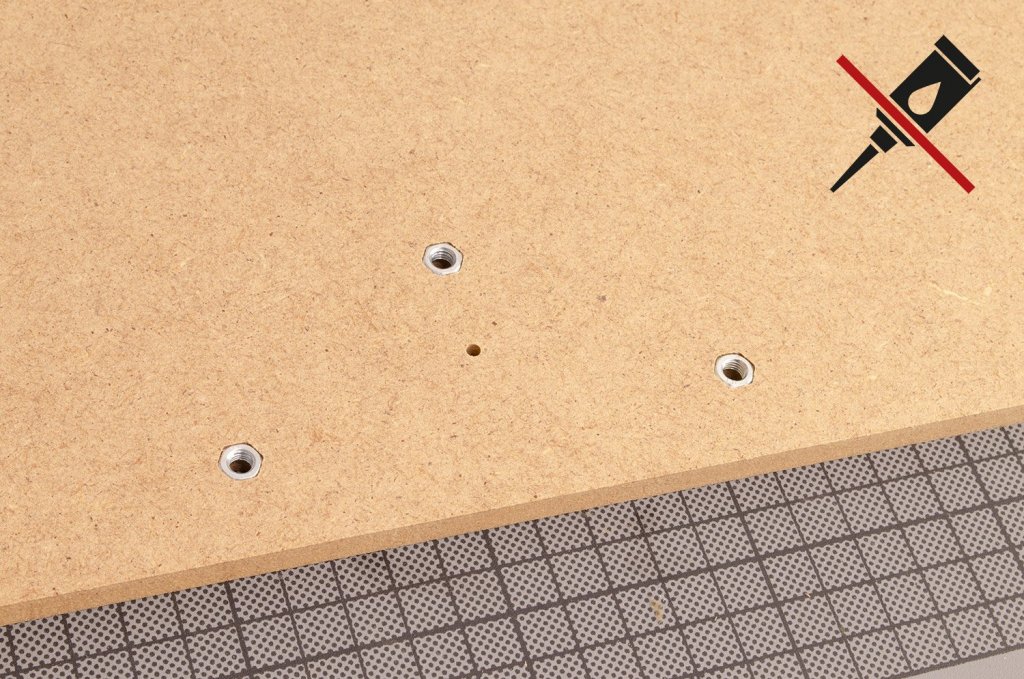
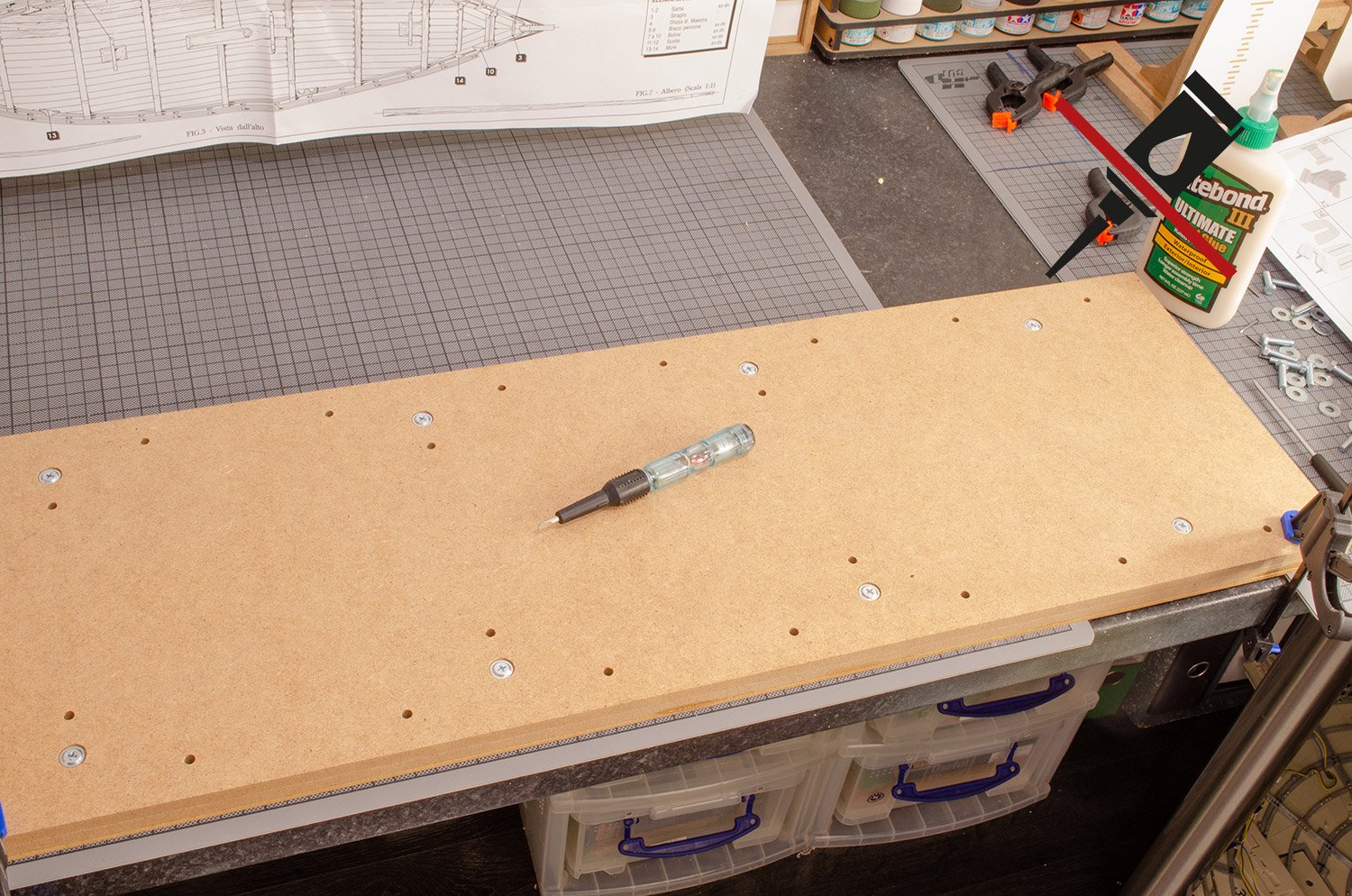
21. You need to clear some workbench space now as we start to assemble the baseboard. Start by pushing the nuts into the hex-head shaped holes.
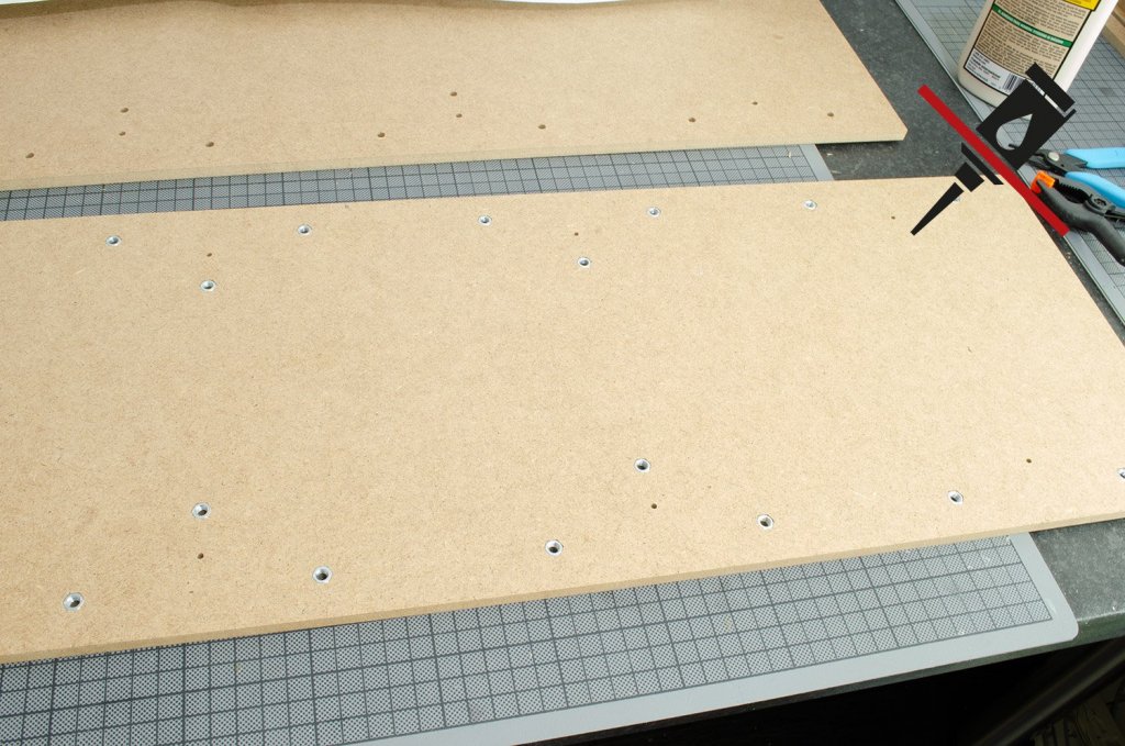
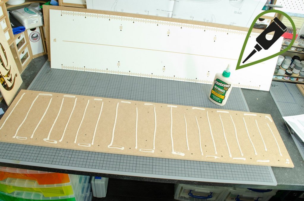
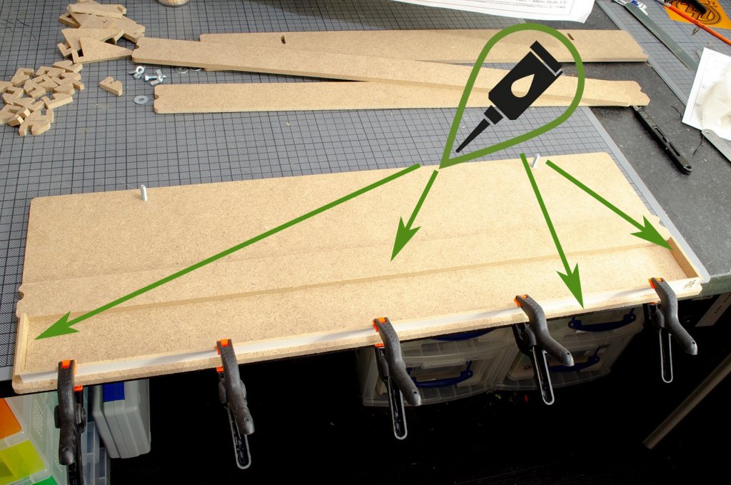
22. Turn over the baseboard so the nuts are UNDERNEATH, and then apply glue to the top side. Fit the white plastic-faced panel onto this and clamp together until FULLY SET!
23. Un-clamp the glued boards and flip it over so the white face in on the bottom. Now, sit the remaining board on top of this, with the screw head indents facing upwards. Using the supplied screws, fit the board into position.

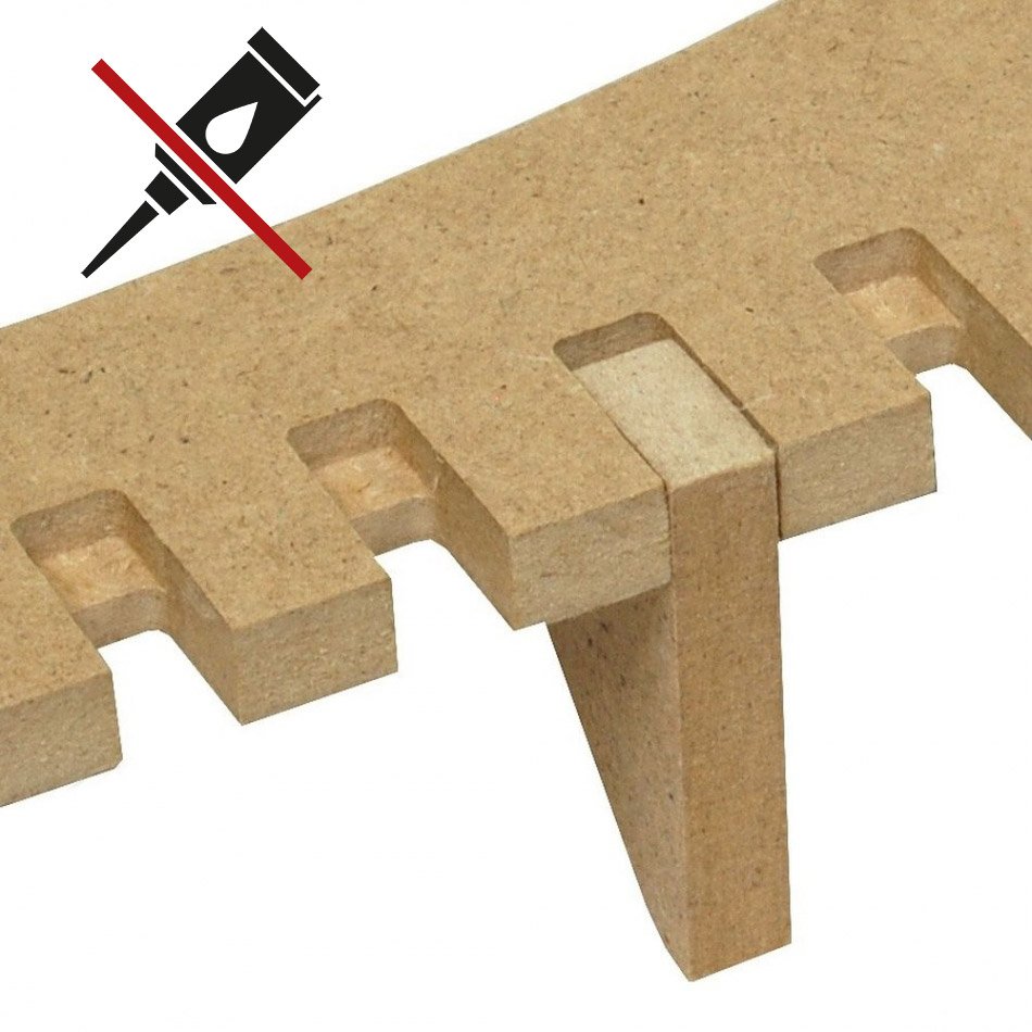
24.Using the supplied bolts and washers, fit the various assemblies to the baseboard, as thus. REMEMBER that the small edge clamps that you see fastened to the horizontal keel clamp halves are only PRESSED into position and they are NOT glued. This allows them to be repositioned to accommodate the positions of the frames/bulkheads of your model.


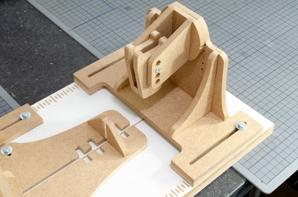

*******NOTE*******
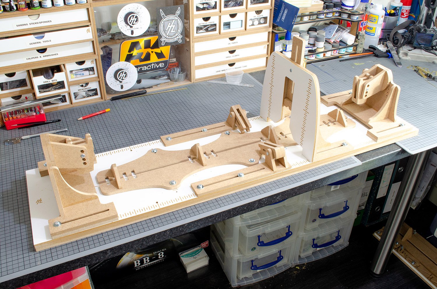
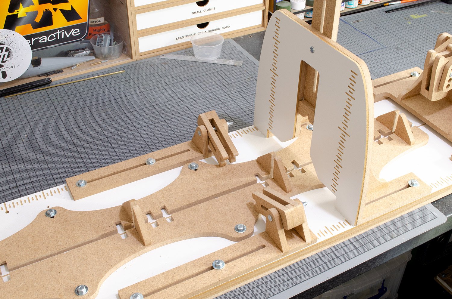
A small number of nails are in included in the pack and there is an amendment sheet to indicate their use. These can be driven through the back end of the various clamps to strengthen them. Remember that these parts will bend as you tighten them, but for me, I would prefer to mostly use thin strips of packing if the keel and bulkheads are significantly thinner than the clamps, as this will remove most of the stress from them.That's it...your Professional Building Slip is COMPLETE!
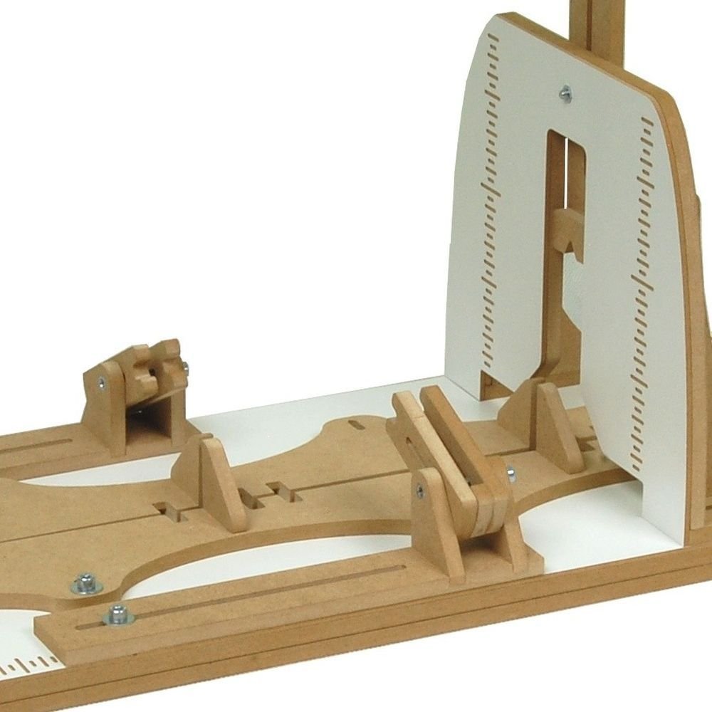
Here are some photos showing its use.
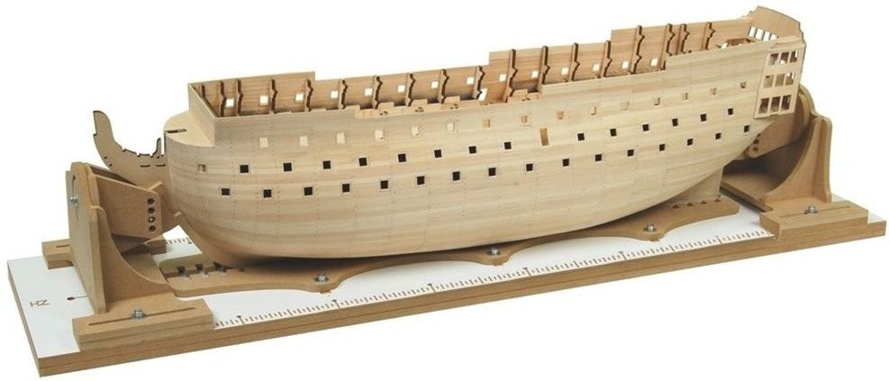
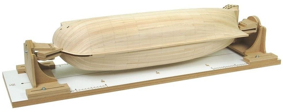
My sincere thanks to Hobbyzone for sending this out for review on Model Ship World. To purchase, click the link at the top of the article.

-
-
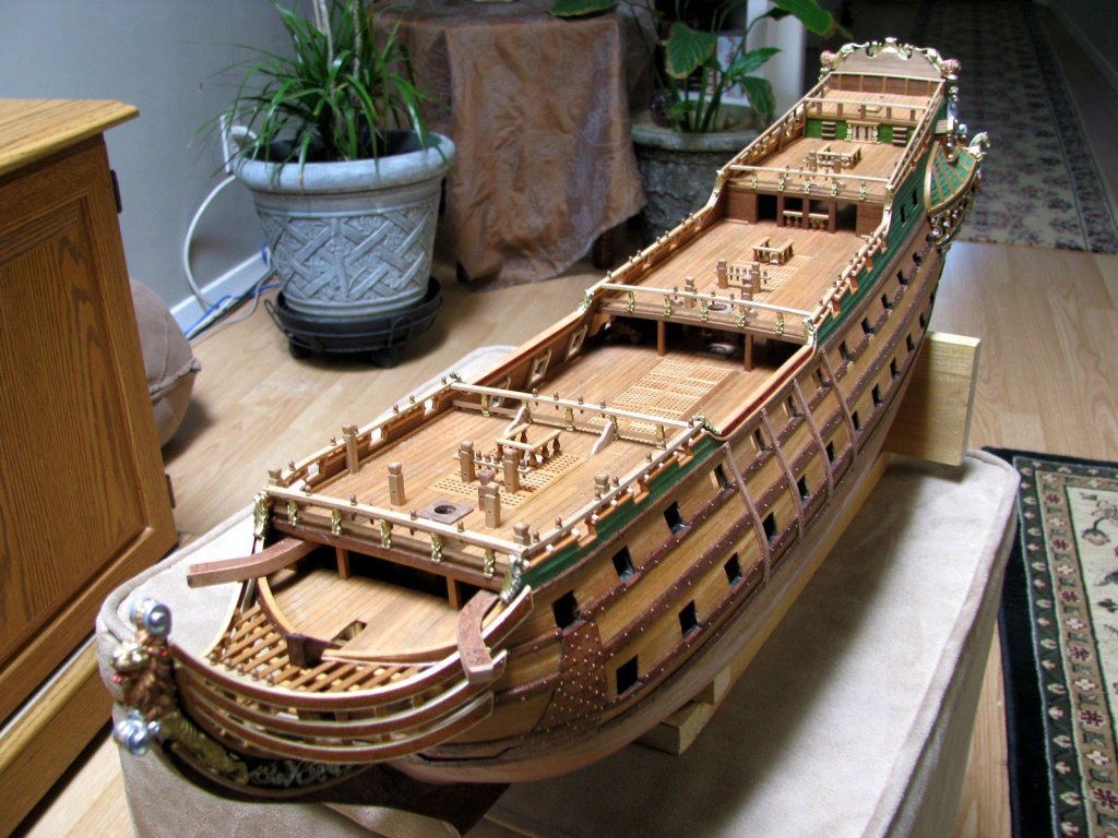
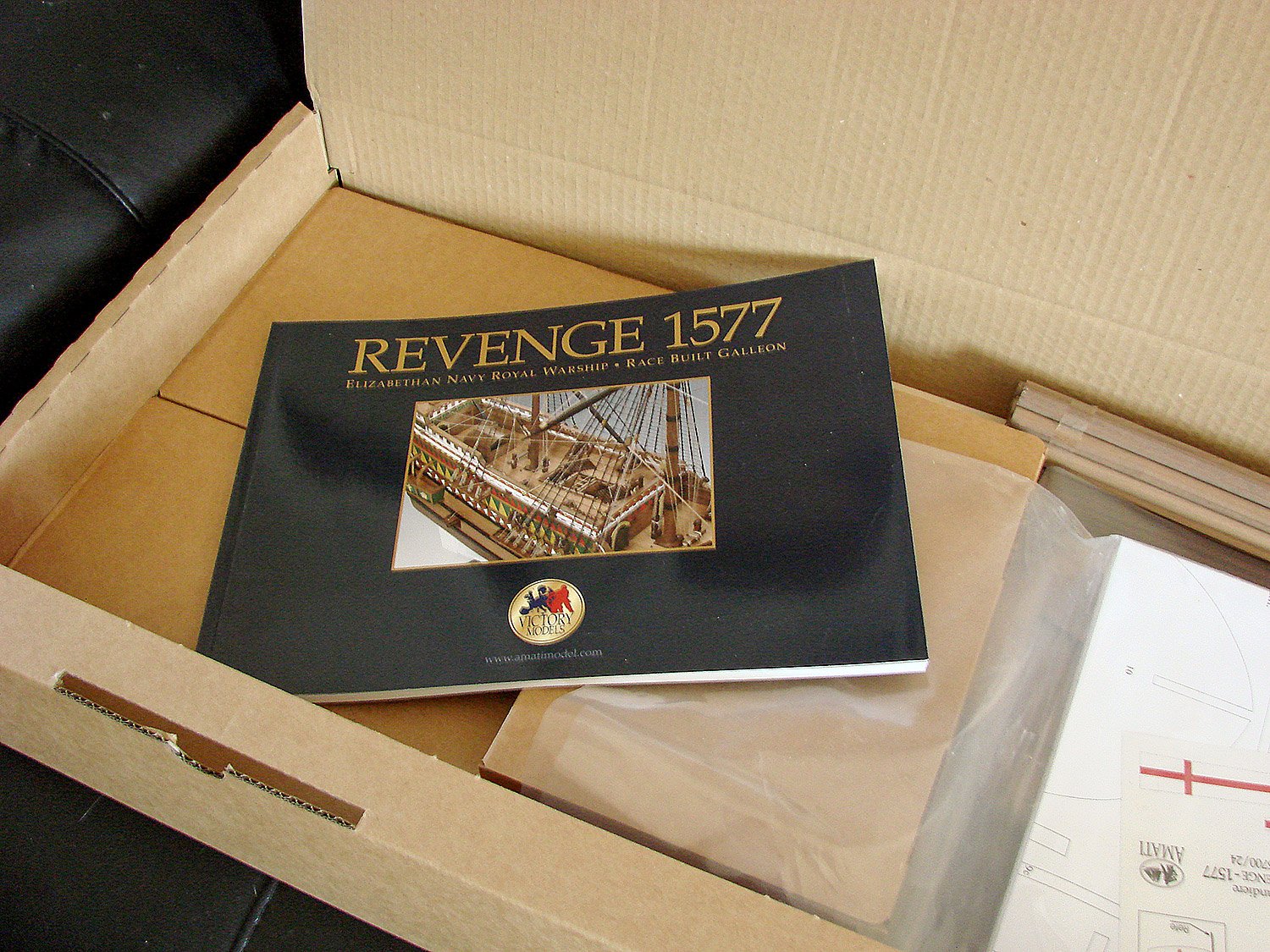
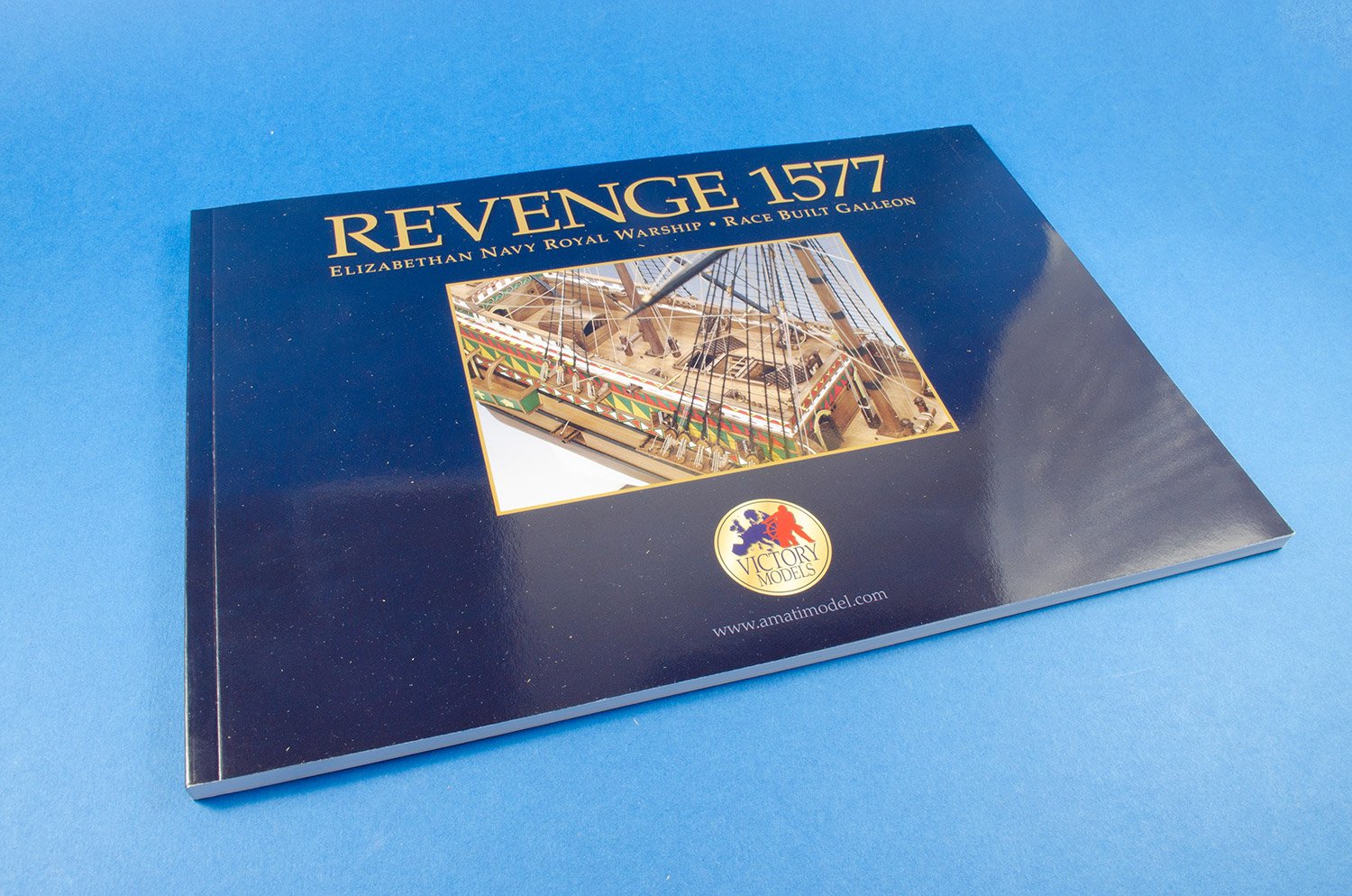
1:64 Revenge 1577 – Elizabethan Race Built Galleon
Amati/Victory Models
Catalogue # A1300/08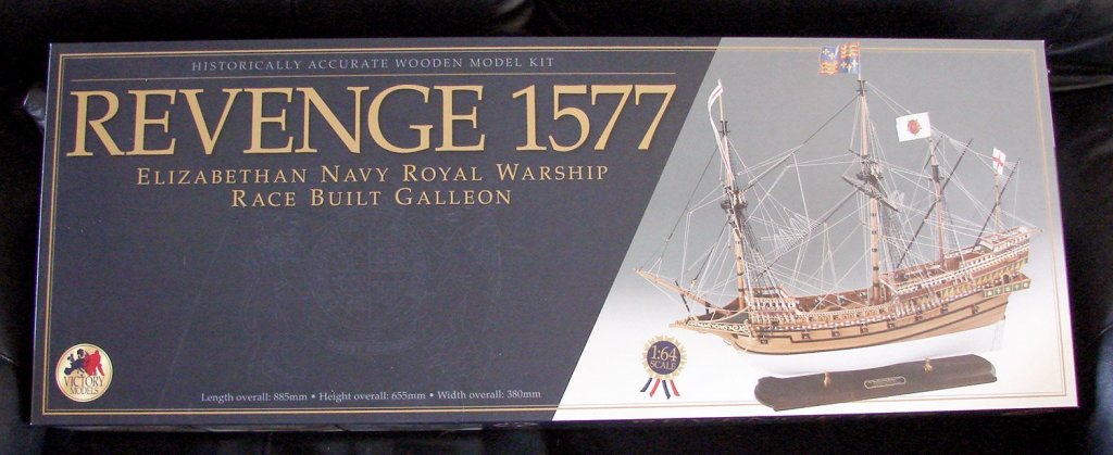
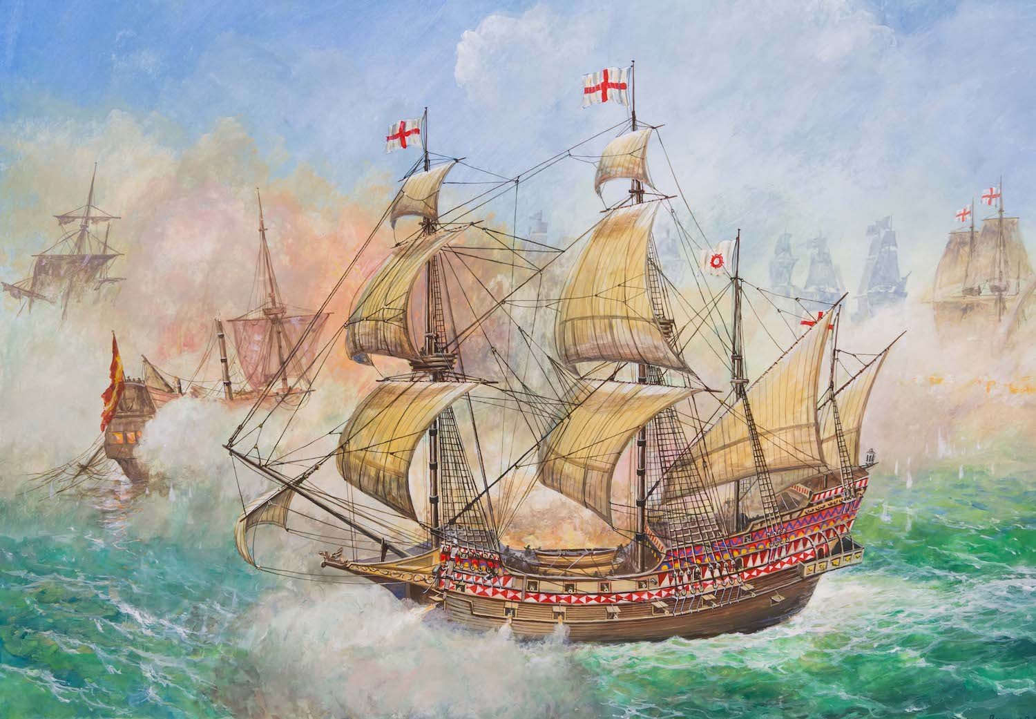
The Elizabethan Navy Royal warship Revenge was built at Deptford and launched in 1577. Revenge was a new type of warship, a ‘Race Built Galleon’. She was built following the direct ion of Sir John Hawkins and supervised, it is thought, by the master shipwright, Matthew Baker. Revenge was about 500 tonnes and carried a crew of around 250 men. Contrary to popular belief, the new race-built galleons were not dwarfed by the Spanish galleons but were of equal or sometimes larger size. It is very easy to see the lines of Revenge as a precursor to the Prince Royal of 1610, the Sovereign of the Seas of 1637, or even the Prince of 1670.
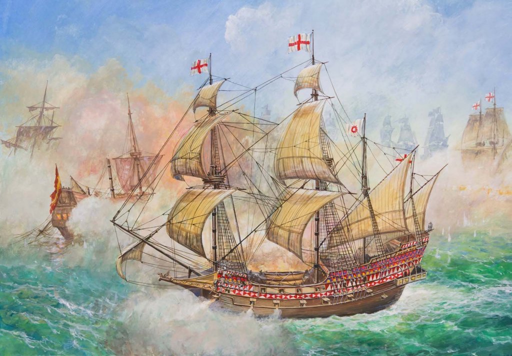
The armament of ships of this period varied greatly; guns might be added, removed or changed for many different types of reasons. Revenge was particularly heavily-armed during her last cruise. On this, she carried 20 heavy demi-cannon, culverins and demi-culverins on her gun deck, where the sailors slept. On her upper decks were more demi-culverins, sakers, and a variety of light weapons, including swivel-mounted breech-loaders, called ‘fowlers’ or ‘falcons’. She was considered the best all-round warship in the fleet, and in 1588 she served as the flagship of Sir Francis Drake, and was involved heavily throughout the Armada campaign. In 1591, Revenge and her captain, Sir Richard Grenville, both earned their place in history when the Revenge was overtaken by a Spanish fleet off the Azores. Sir Richard Grenville fought the Spanish fleet for 16 hours, crippling and sinking many Spanish ships before being forced to surrender.
The kit
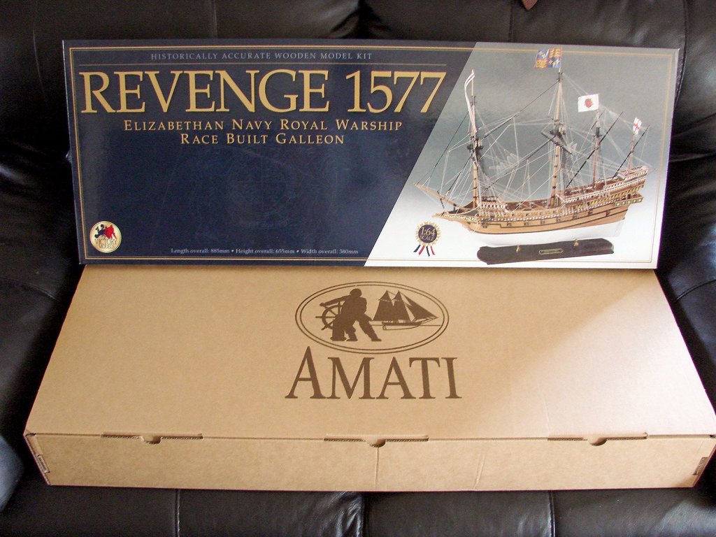
Revenge 1577 is an Amati/Victory Models joint venture, as was the HMS Vanguard 1787 that I reviewed recently. However, this particular kit was only released in 2015, having been designed by Chris Watton. Like Vanguard, Revenge is packaged into the same monster-sized box so will look pretty imposing when it arrives, plus it will really please your postman who will have to bring it to your door!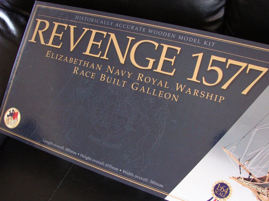
If you are remotely interested in this particular kit, you will have doubtless headed to Amati’s website for information on this release. That is given as thus:
- 20 sheets of plans
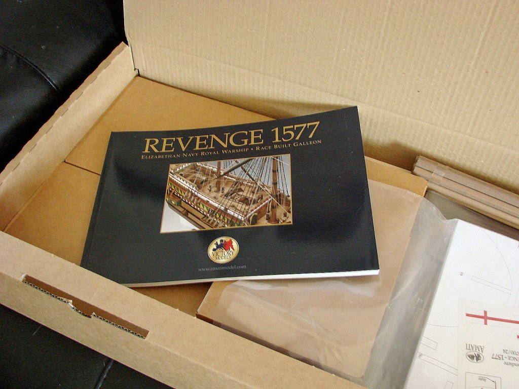
- 96 pages full colour building manual with step by step instructions
- Laser cut plywood, hardwood and MDF
- Double planked hull
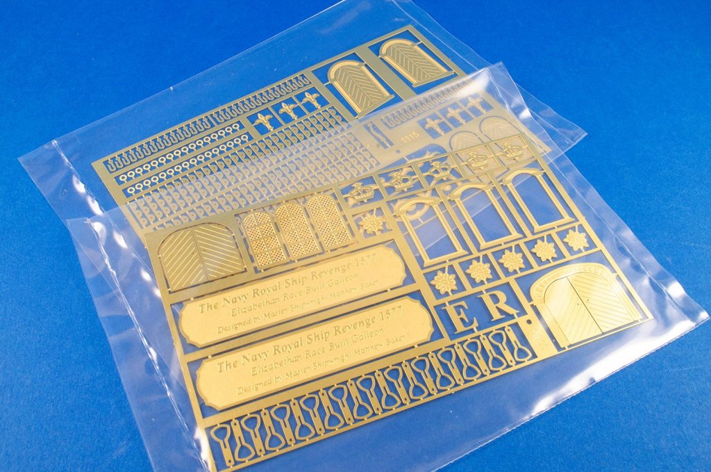
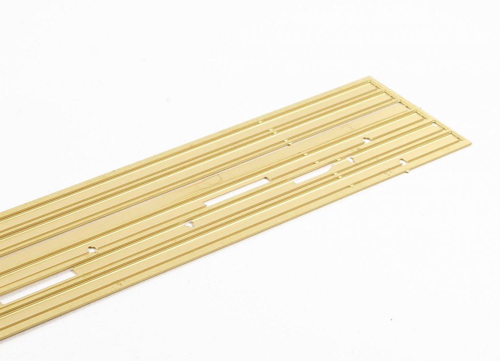
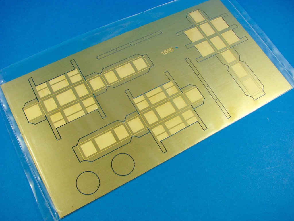
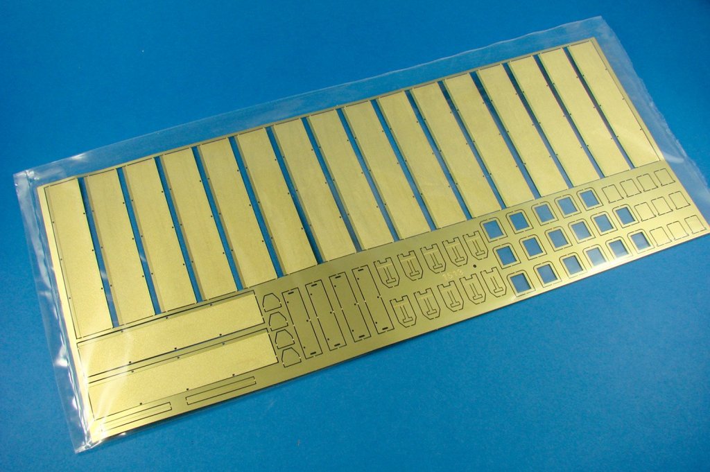
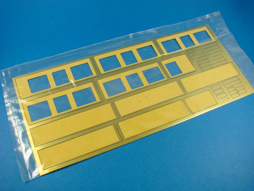
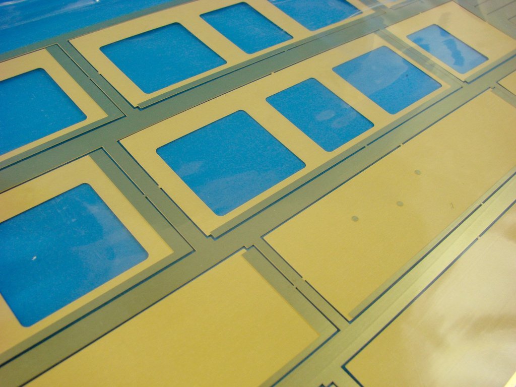
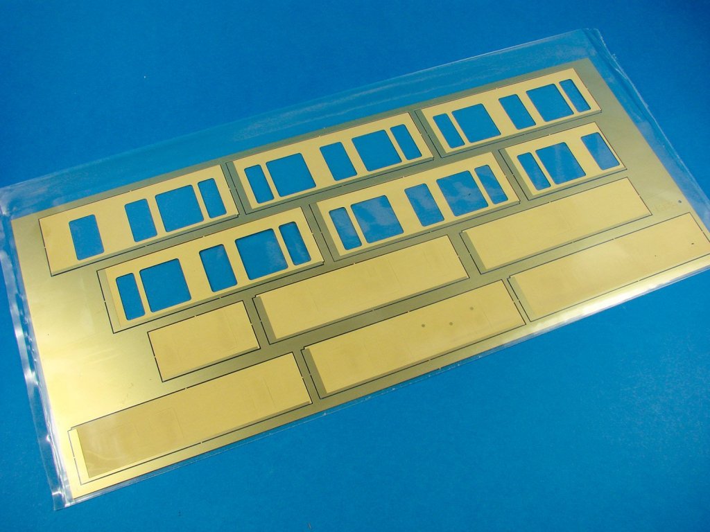
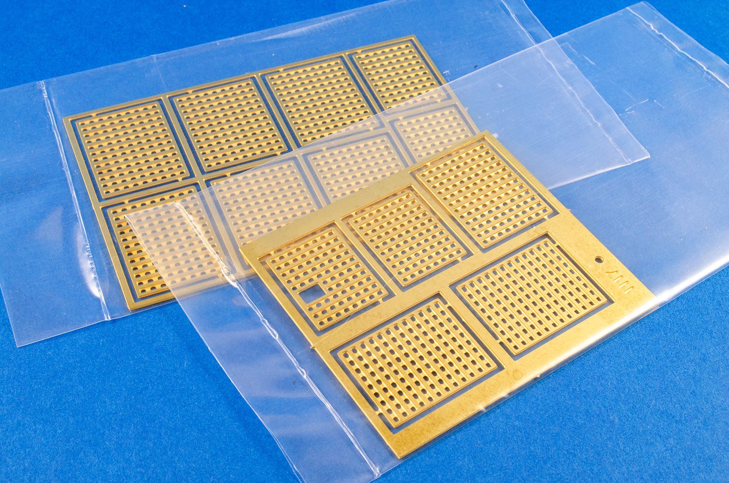
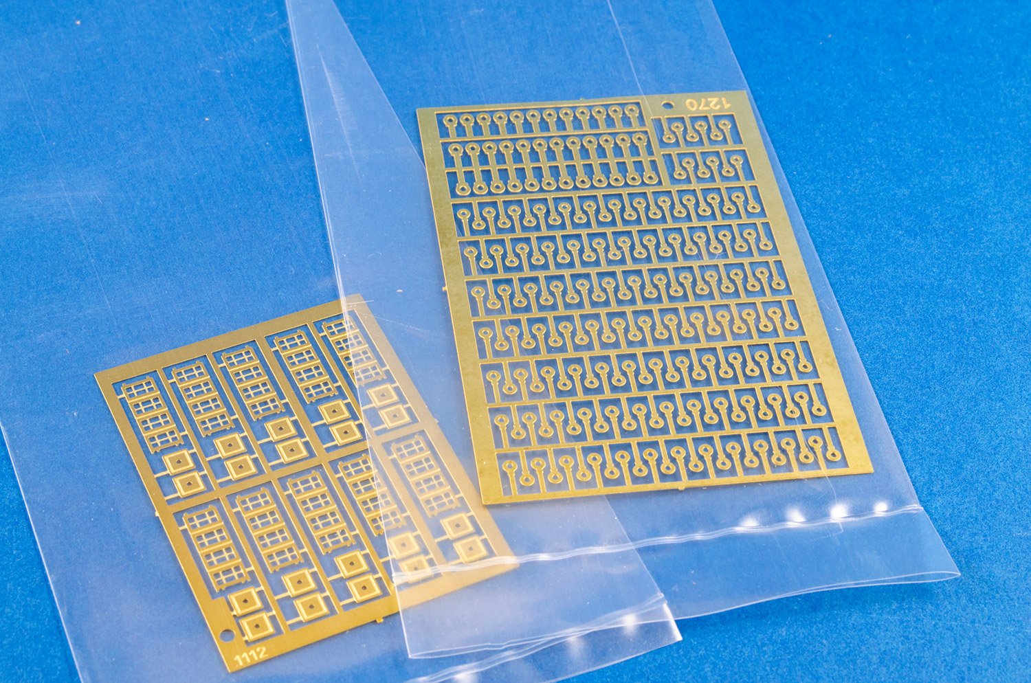
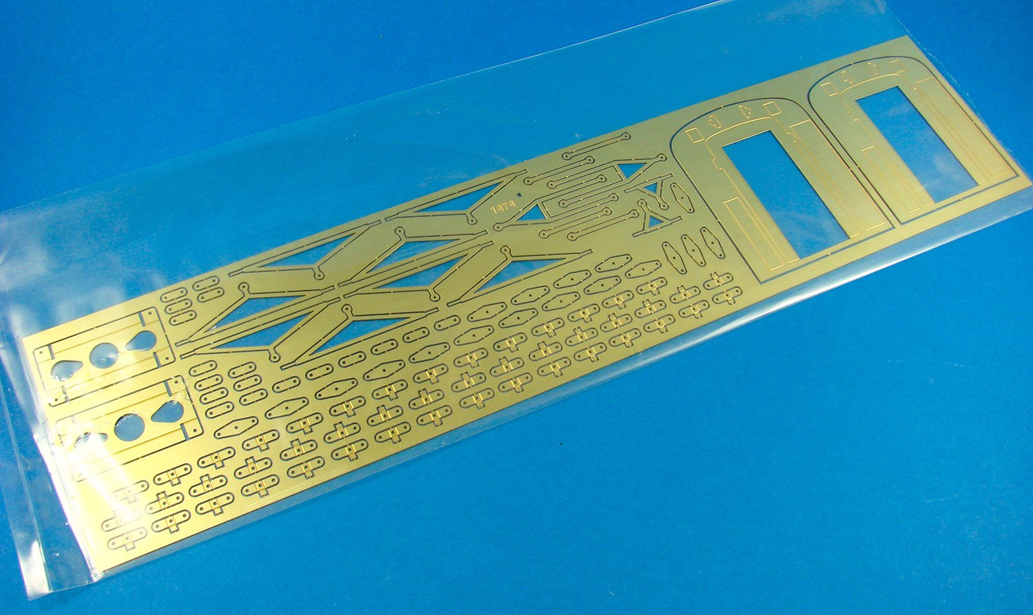
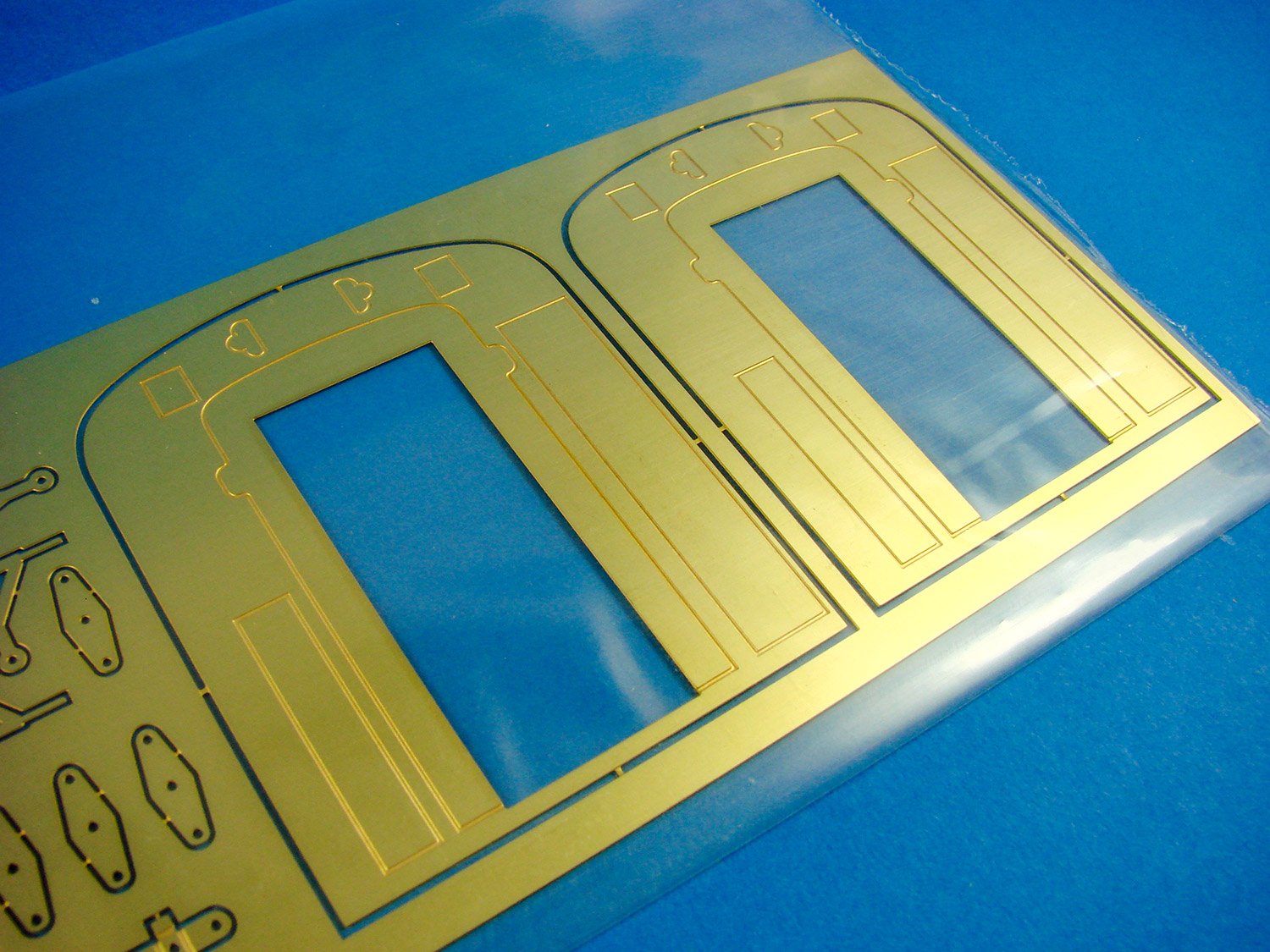
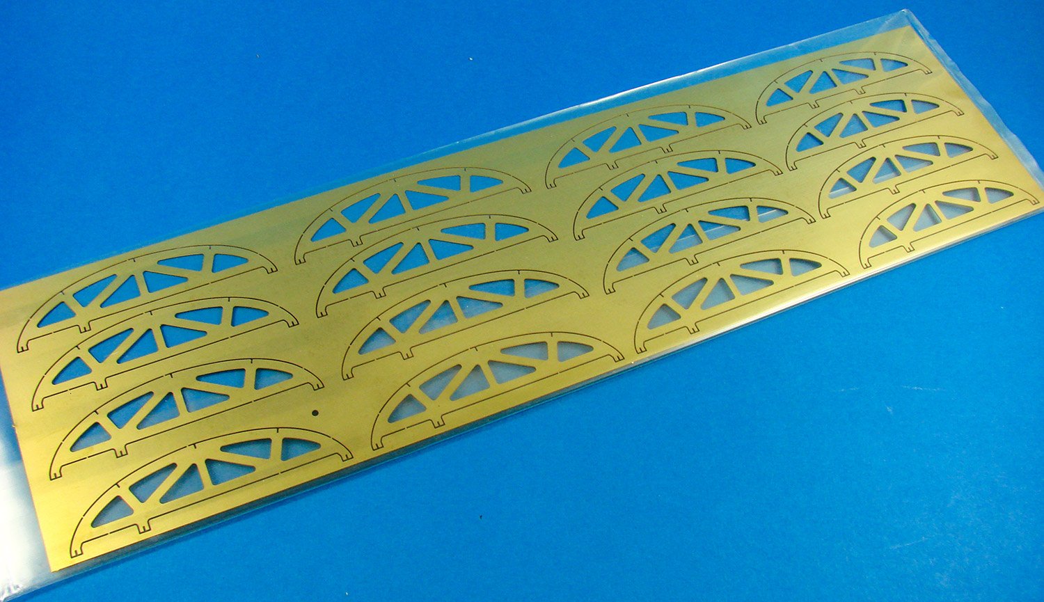
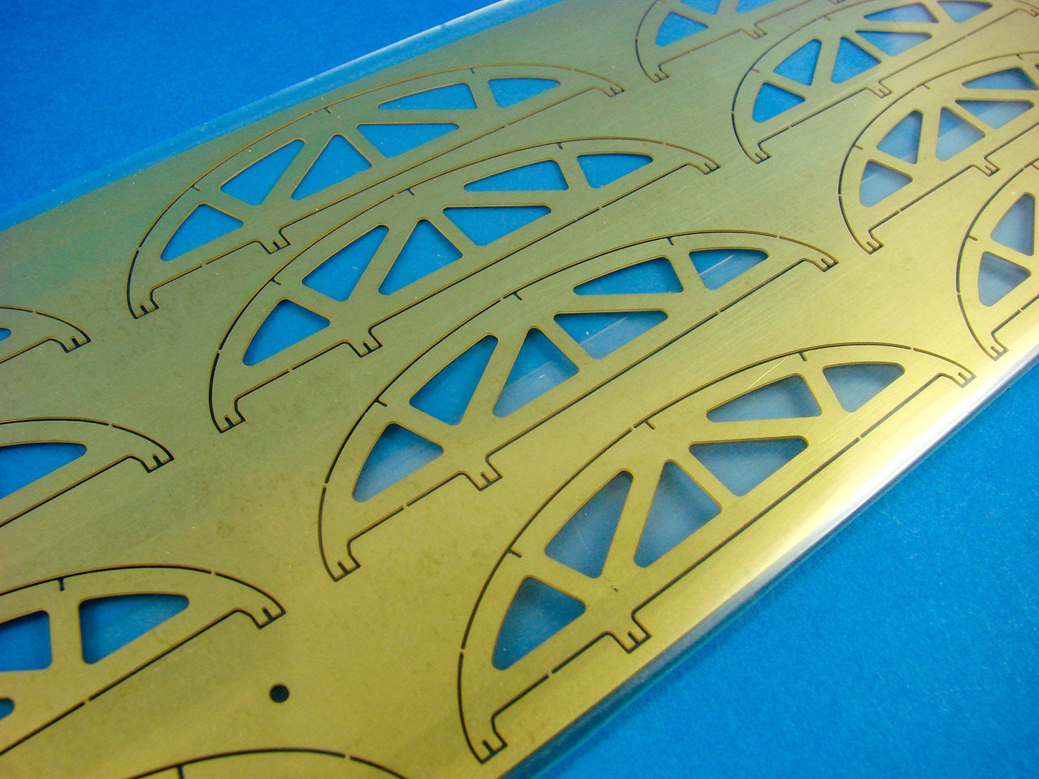
- Highly detailed photoetched brass parts
- Precious paper decorations
- Brass culverins and burnished metal casted cannons
…now it’s time to look deeper at this kit.
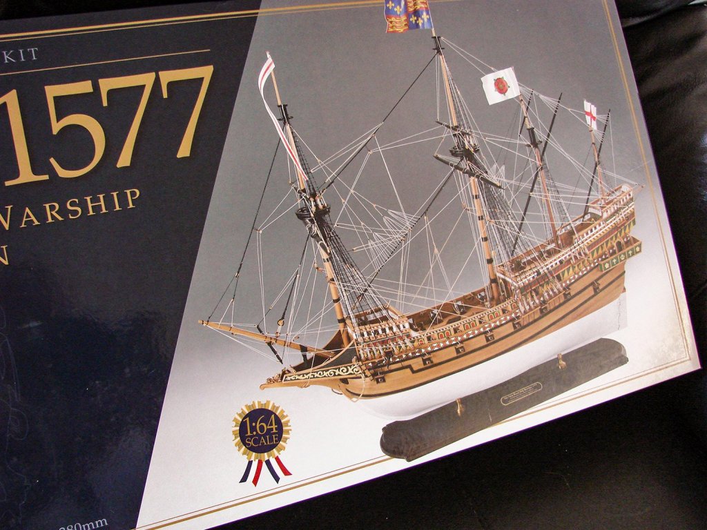
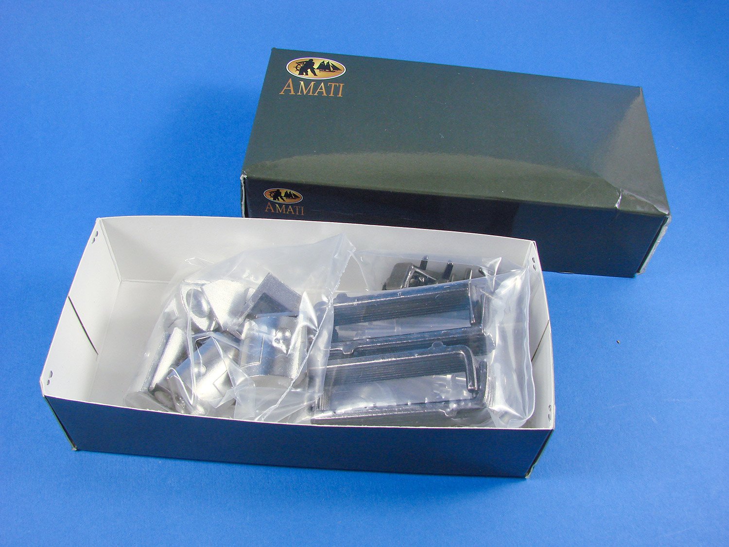
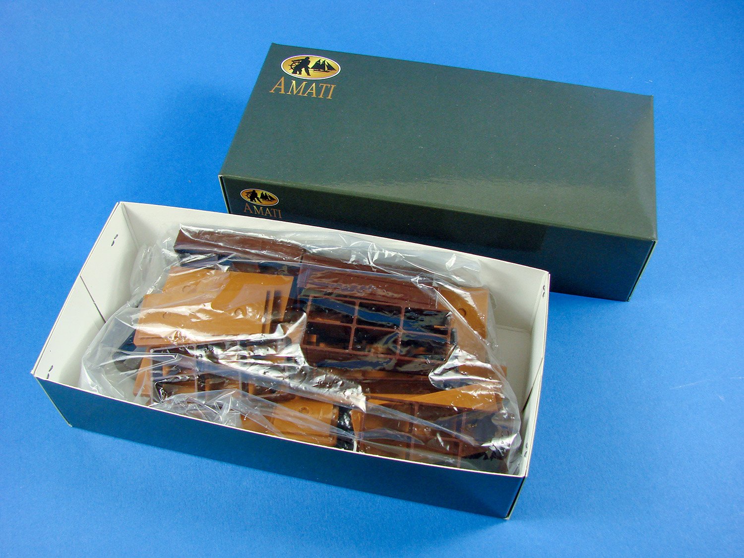
Amati’s artwork for the box is perhaps a little more restrained than that of Vanguard, but still looks equally as impressive, with images of the completed model on the sides of the box. It’s also a fairly weighty box too. When you lift off the lid, you’ll note that the lid is merely decorative, with a single-piece rigid corrugated card box underneath. The lid is secured via large tabs and lifts up to reveal contents. The box is designed to hold large weights within and is very robust. Inside, we have several packets of laser-cut MDF, ply and walnut, a heavy pack with 20 plan sheets, a full-colour perfect-bound instruction manual, bundles of strip wood and dowel, printed flag set, and three large boxes of fittings/components. Everything is packed so as to minimise any movement of items within, and indeed, my sample looked like it had just been packed at the factory.

Opening the first components box, we see a pack of sail cloth, just in case you wish to fit them to your model. I know the convention is to leave sails off, but at lease the option is provided for you here. The material is very pale and would benefit from some ageing using whatever your preferred method.
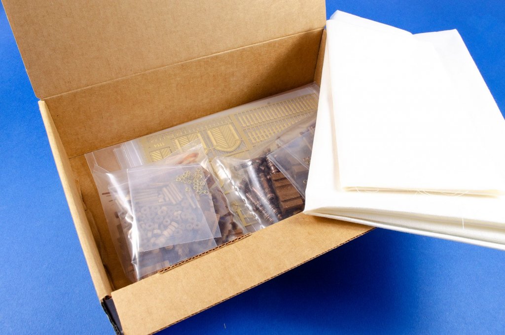
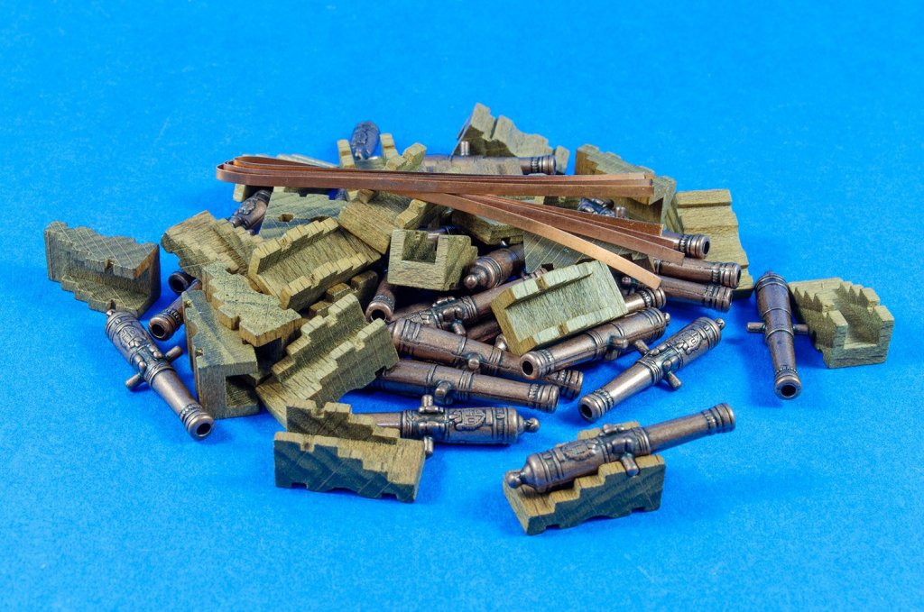
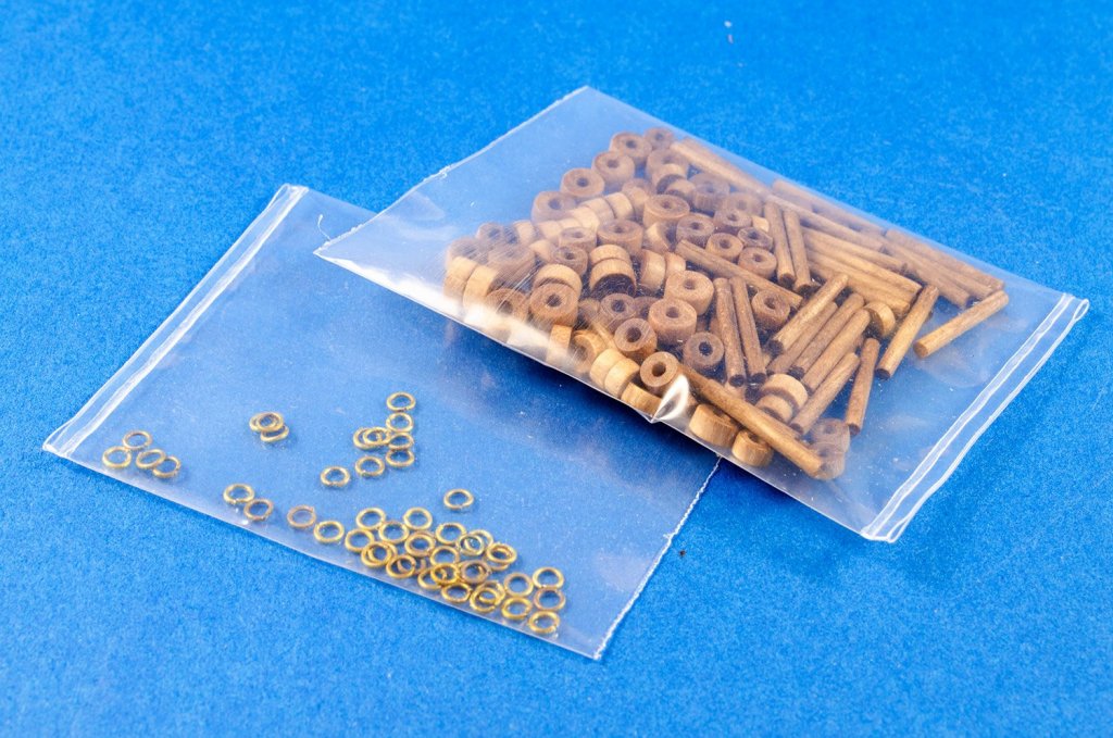
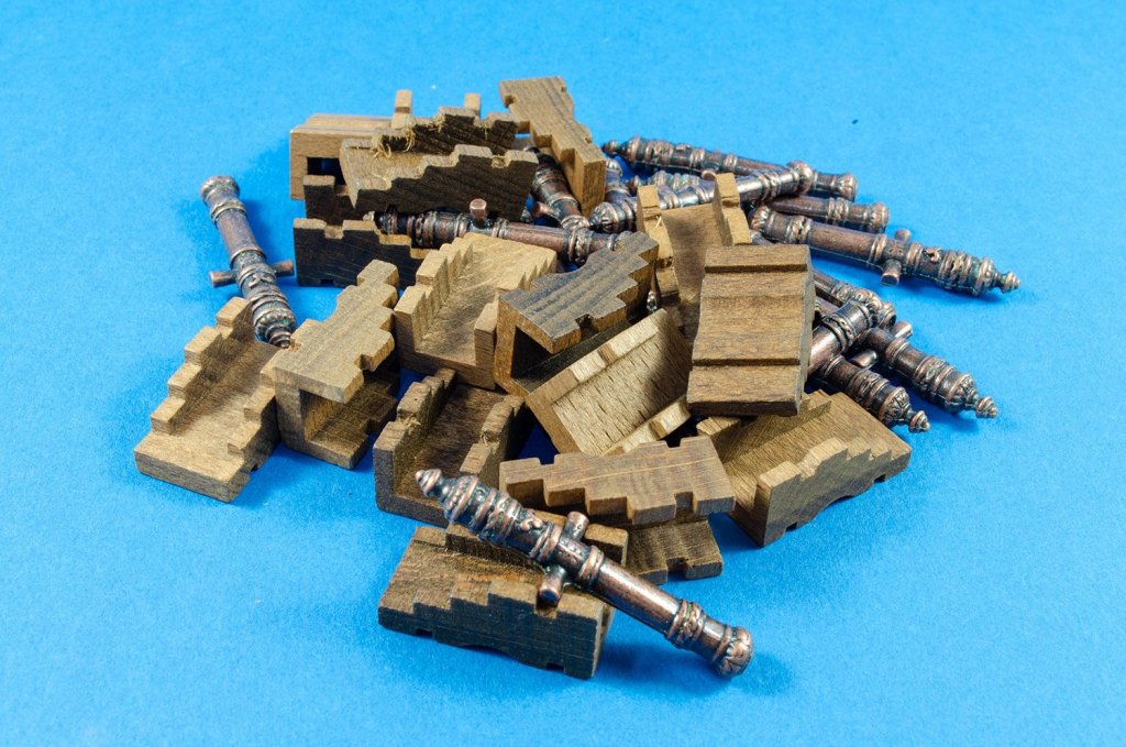
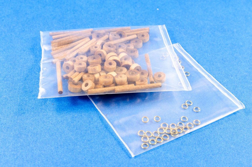
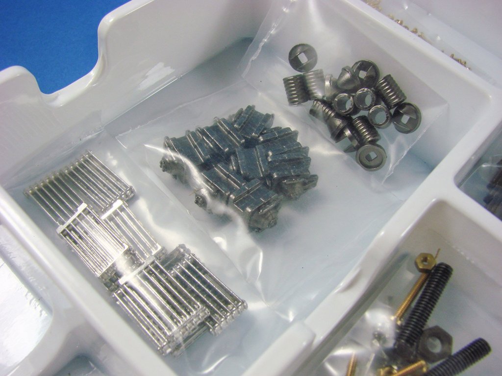
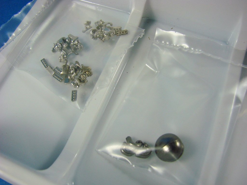
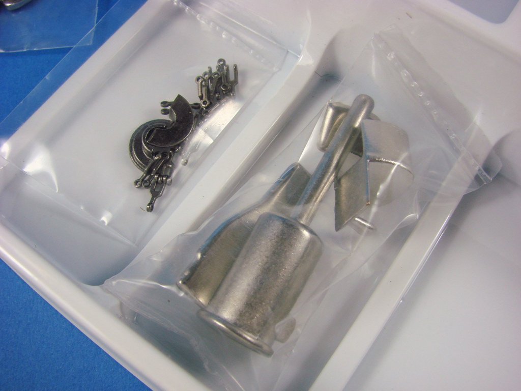
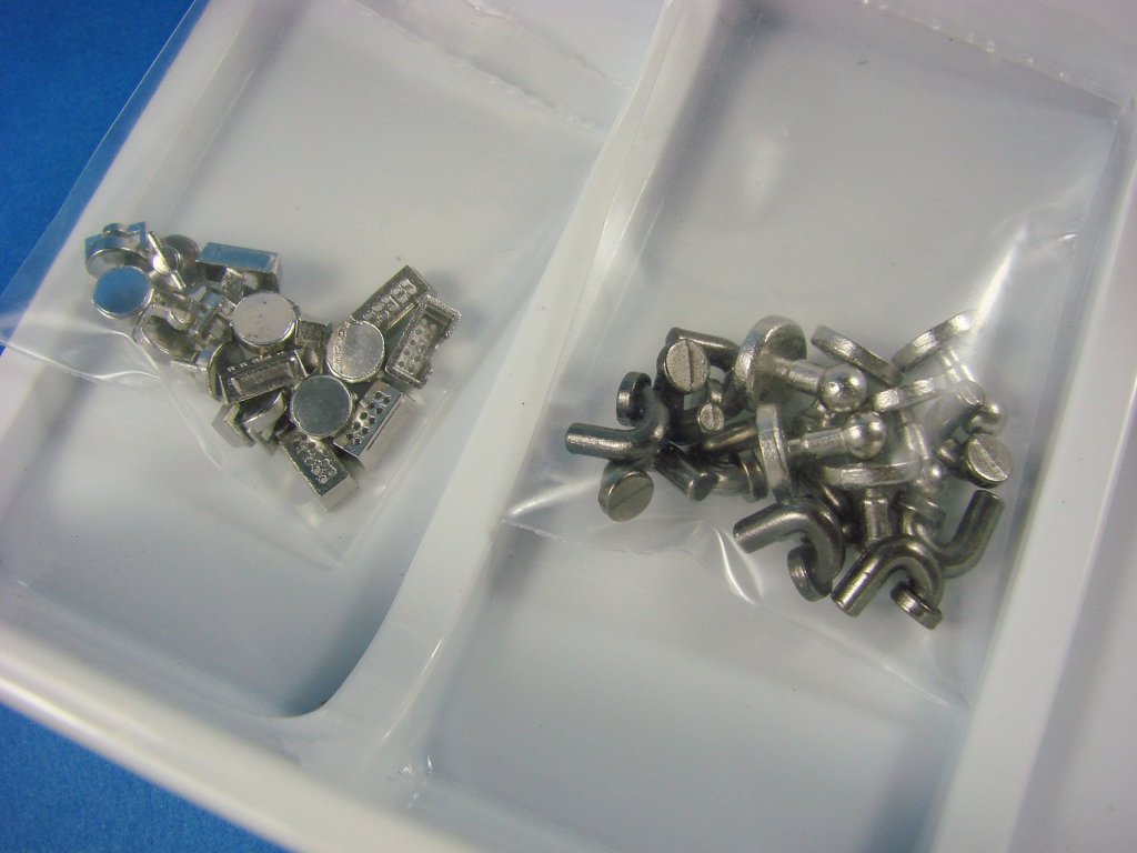
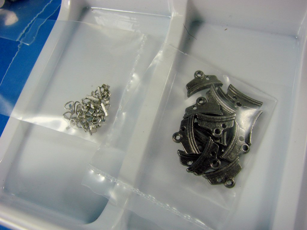
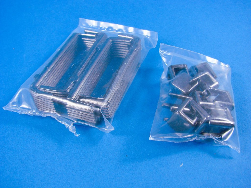
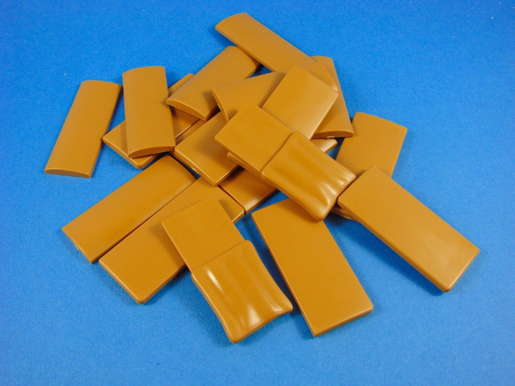
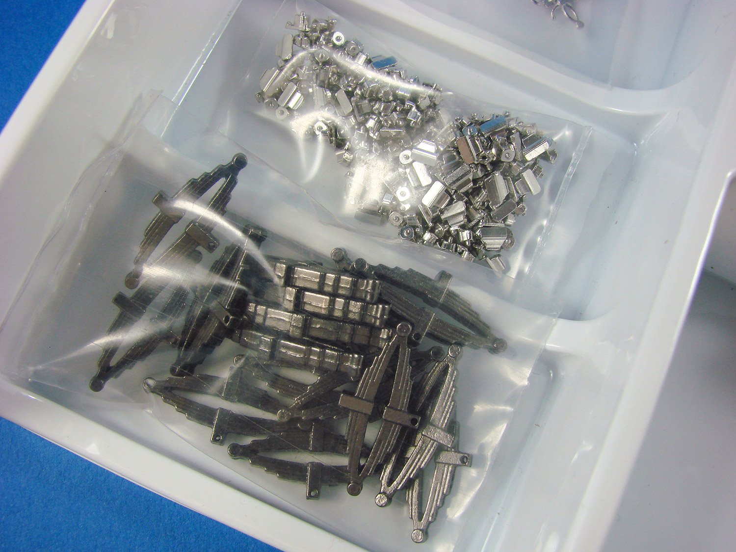
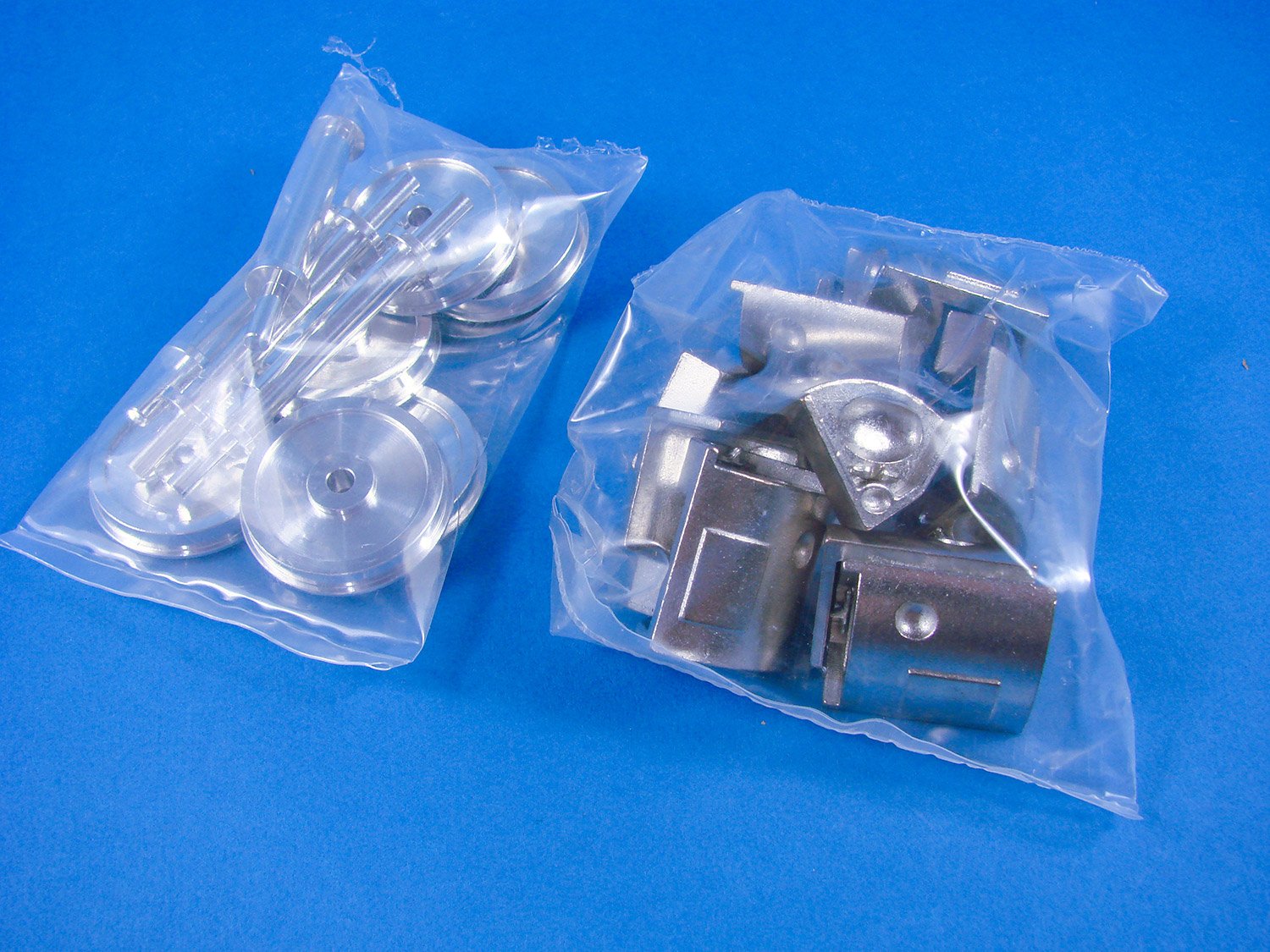
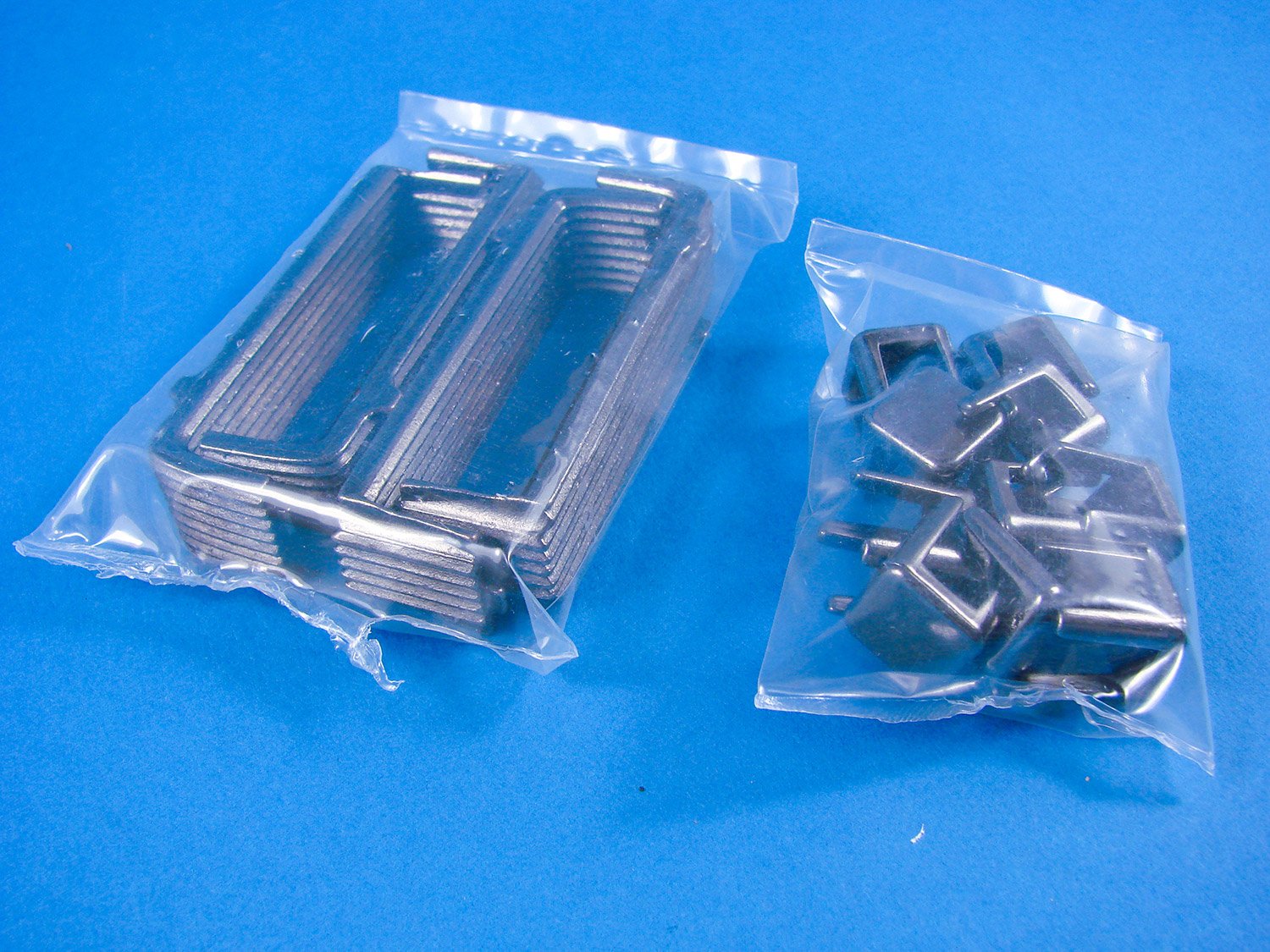
Two thick clear bags are now seen, and these include parts for the cannon, in two sizes. The main bags themselves contain some beautiful cast guns with decoration on them, and these have an antiqued finish. I would personally paint these in iron, and the embellishments should look excellent if you then buff them up. Unlike Vanguard, this kit provides wooden gun carriages, machined as a single piece. Again, I am more than happy with this inclusion, and they appear to be walnut. A long piece of thin, narrow copper sheet is included to make the straps from. Two further packs include the eyelets, plus wooden wheels and axles. Very happy with those.
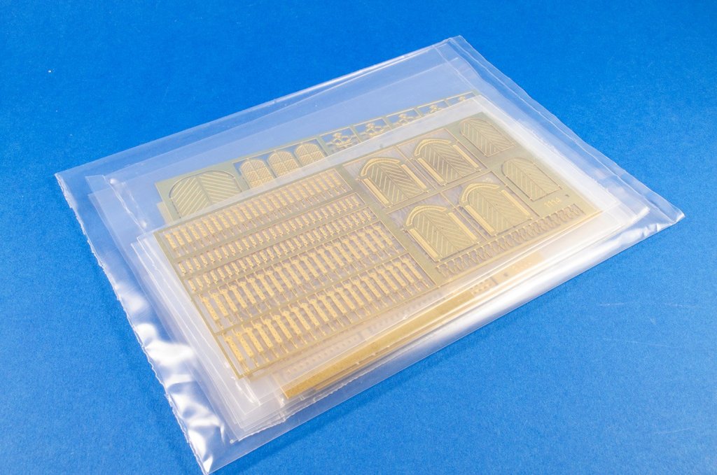
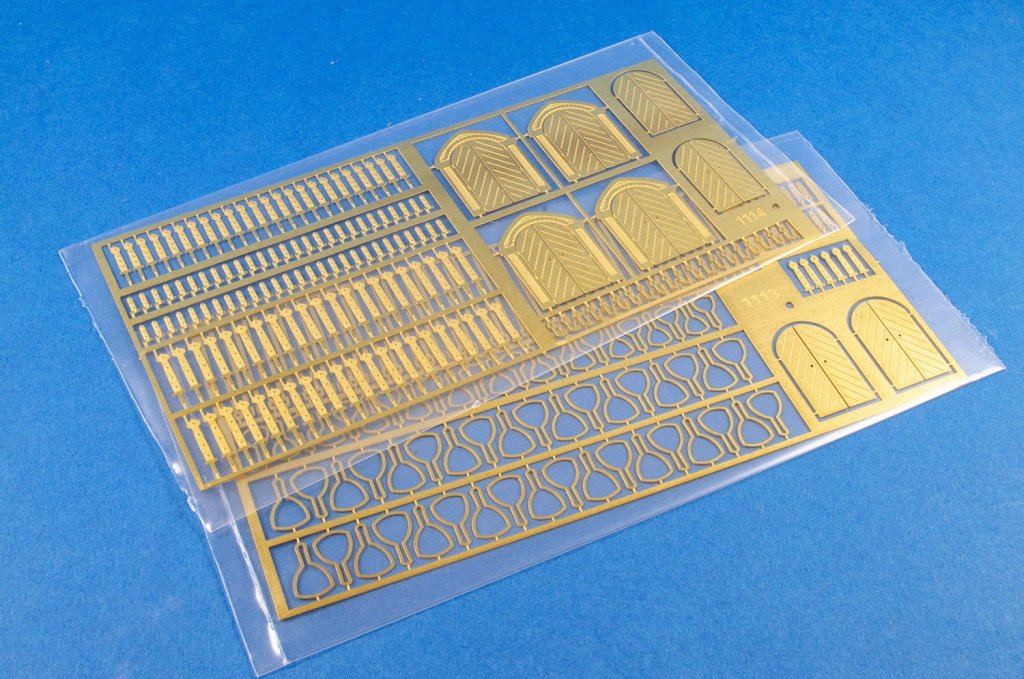
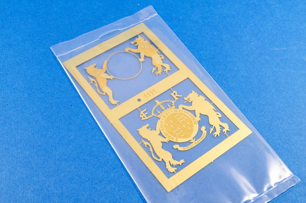
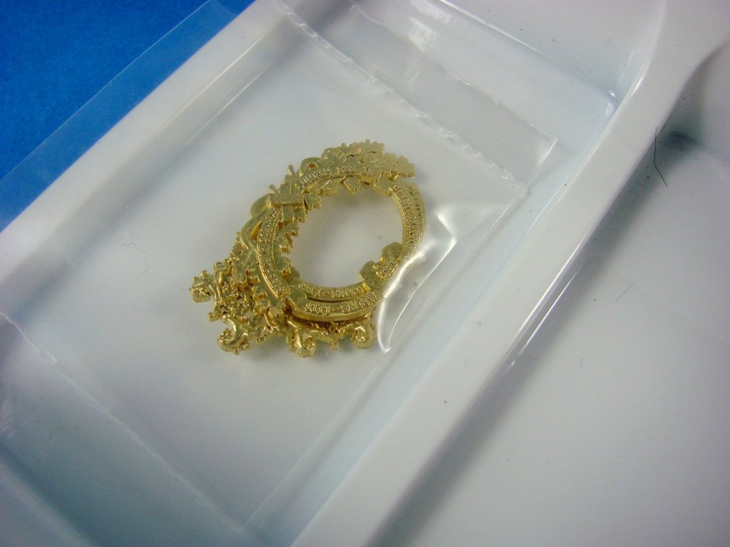
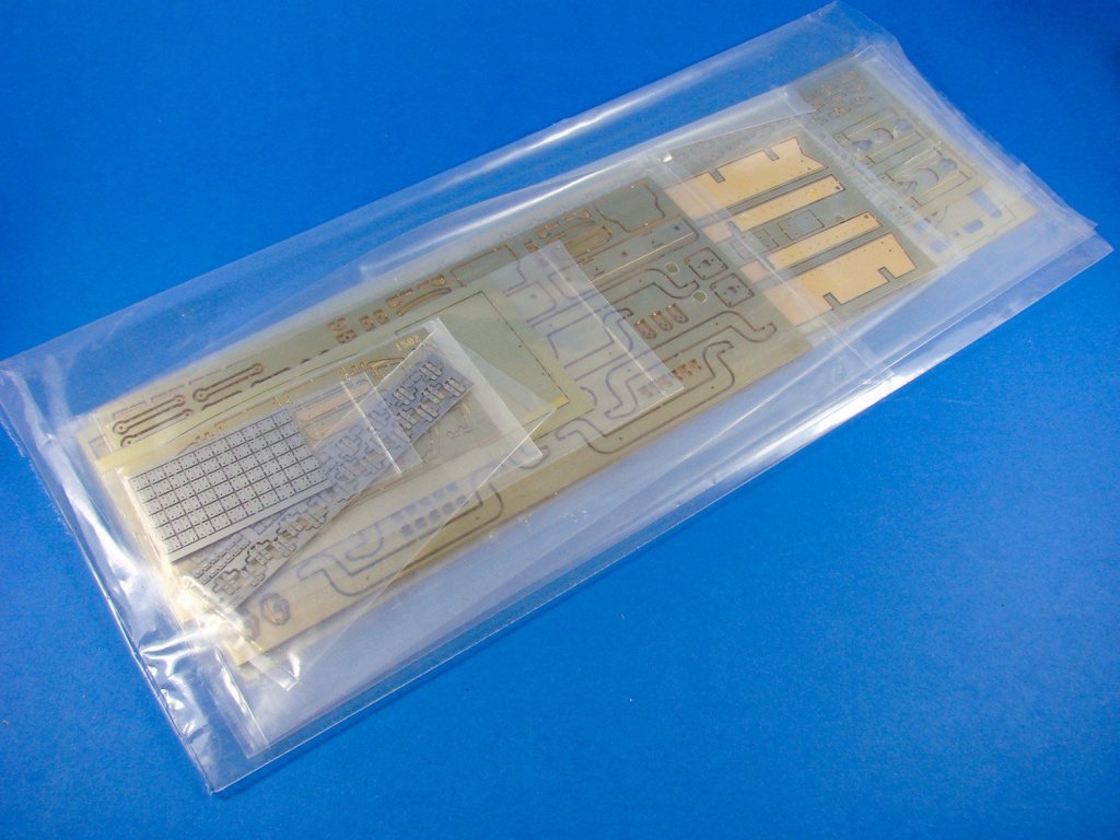
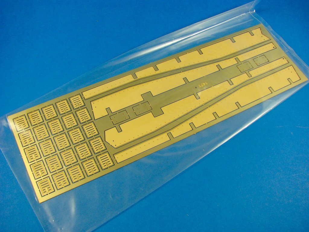
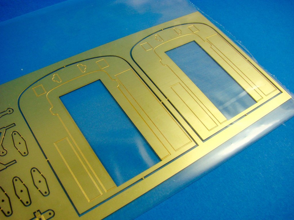
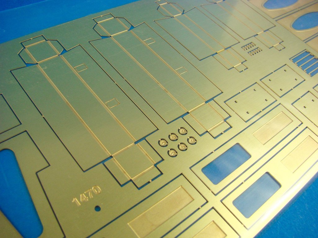
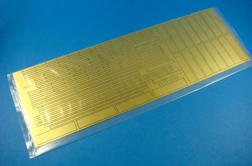
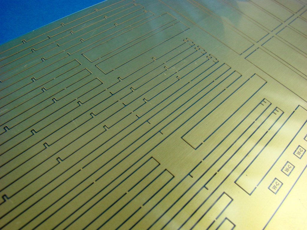
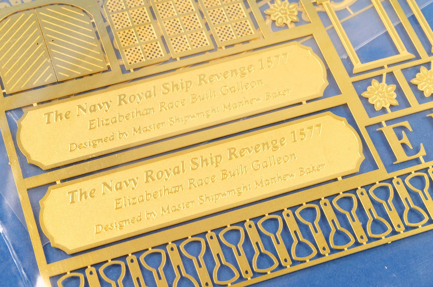
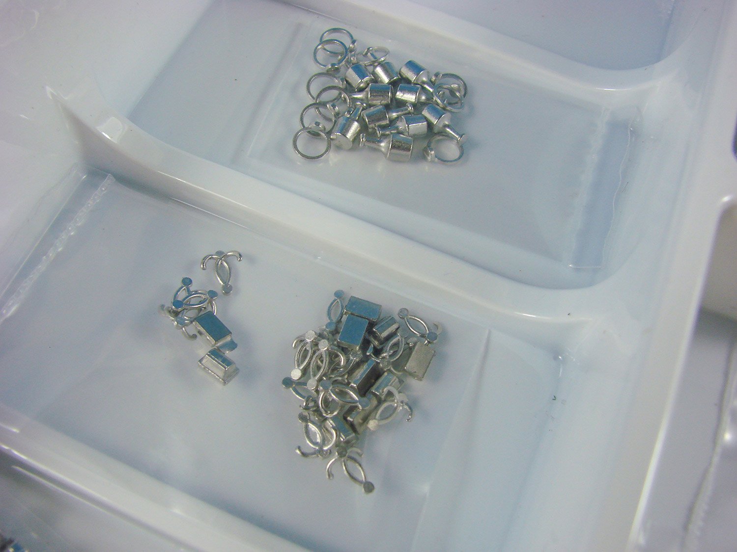
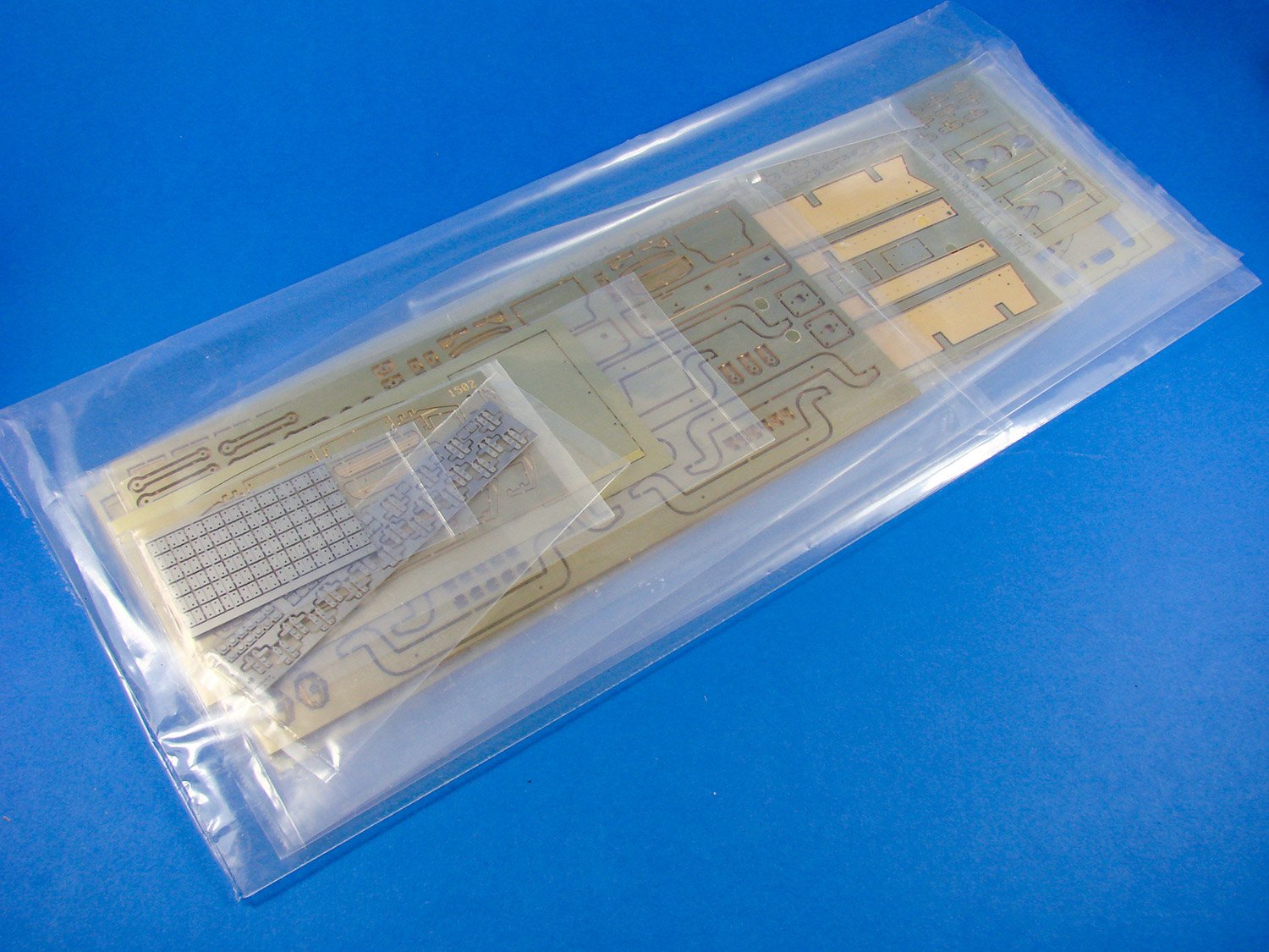
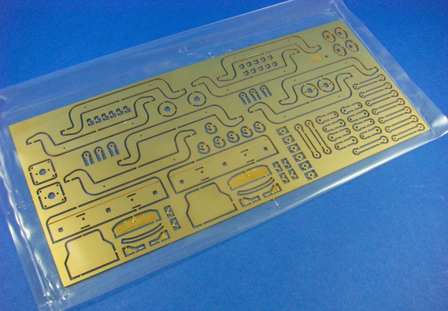
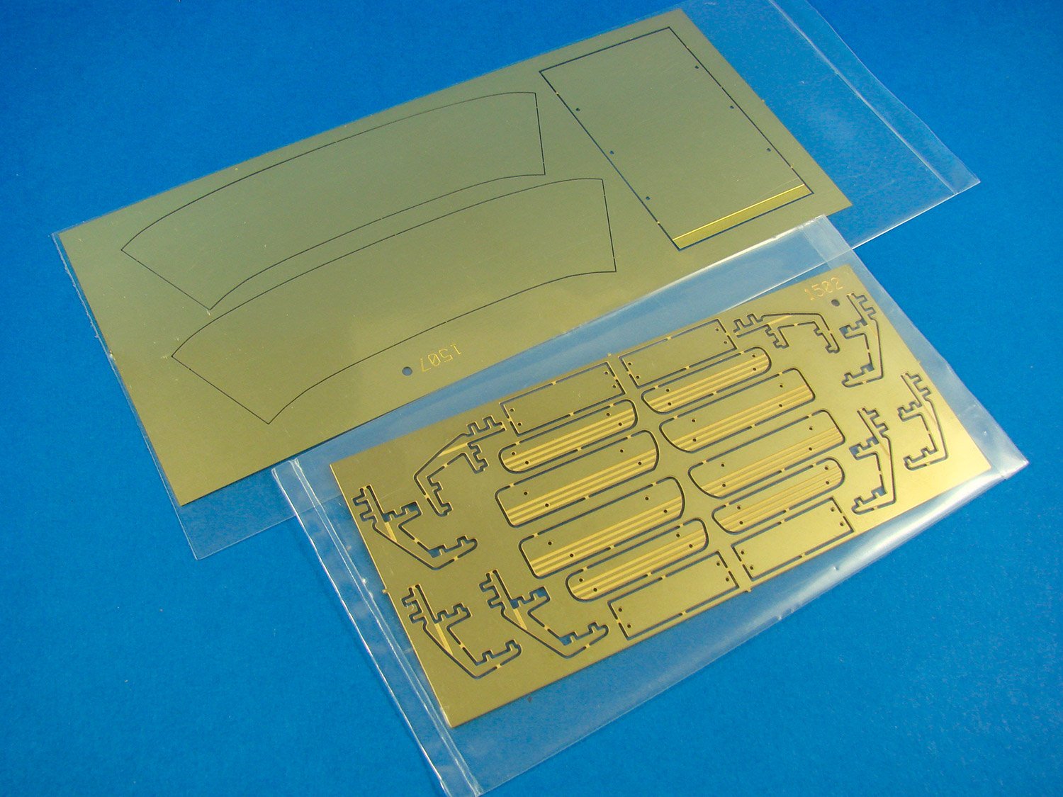
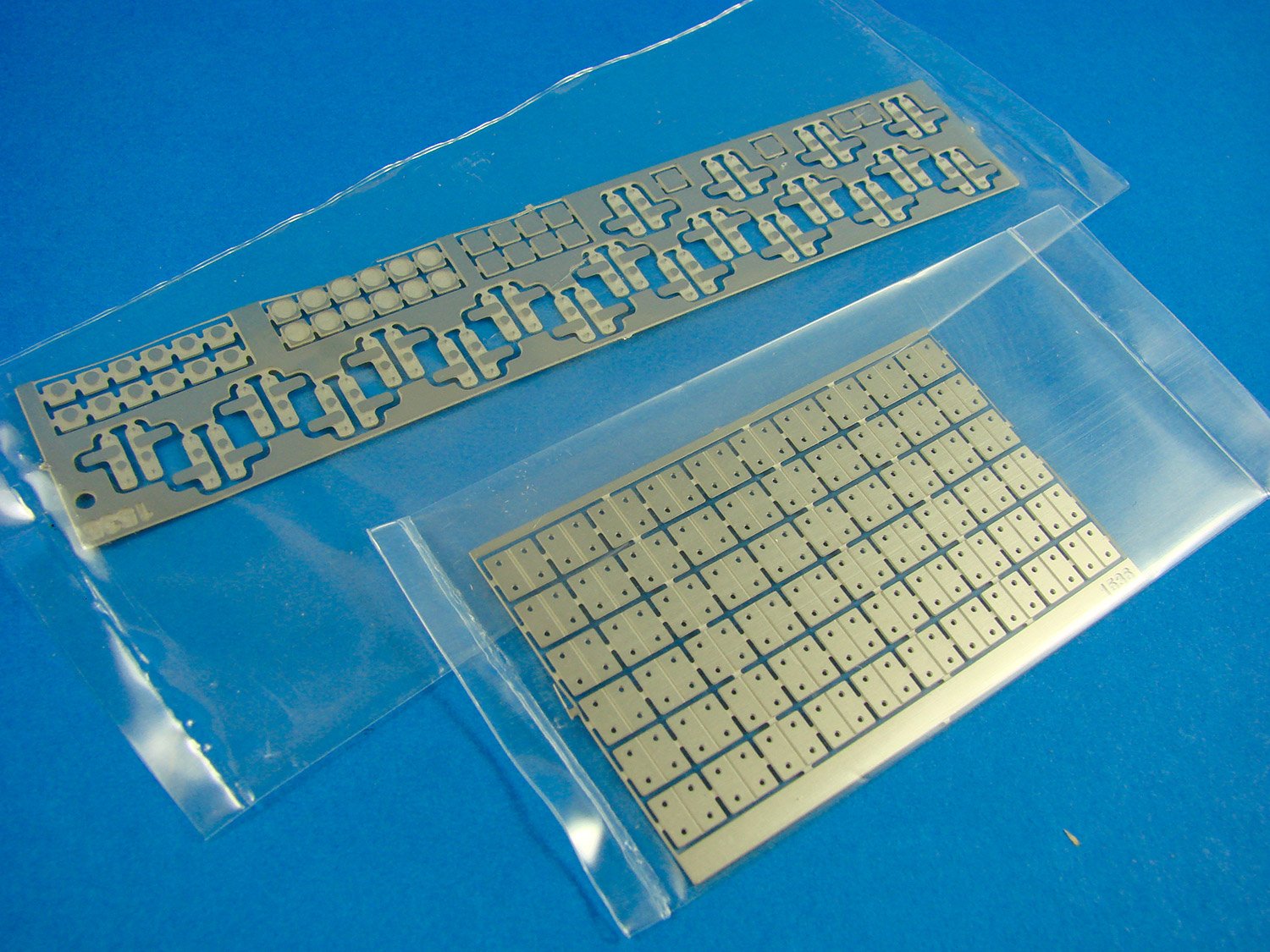
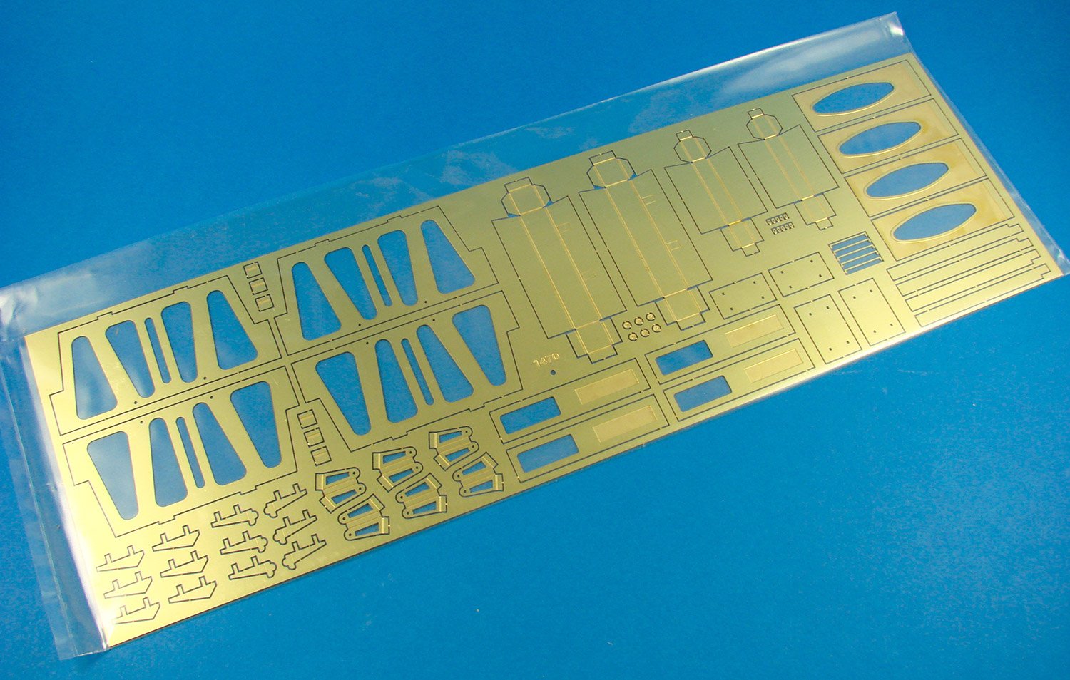
Underneath these bags lie a few clear sleeves of photo-etch parts. Here you’ll find parts for the chain plates and for deadeye securing, doors, grates (maybe they were cast iron on these ships?), and also the Royal crest that adorns the transom. This is built up from two layers of PE and will require some painting. Two name plates are also supplied for the base. You will need to paint the lower relief and then drawn the part over fine abrasive paper to remove anything on the upper relief.


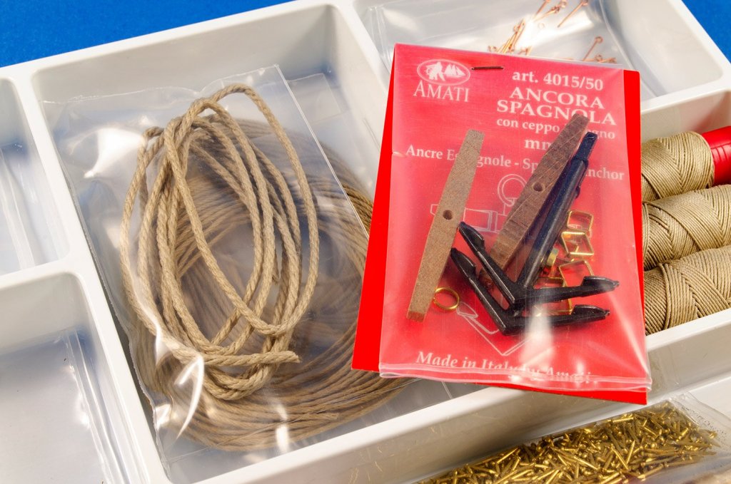
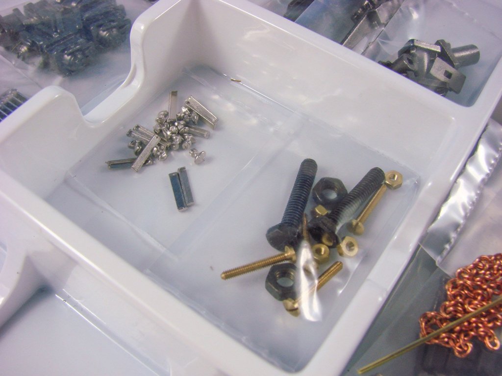
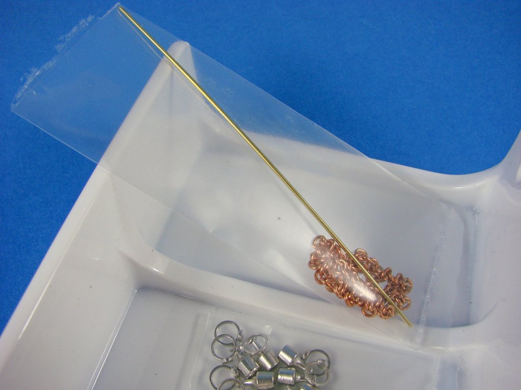
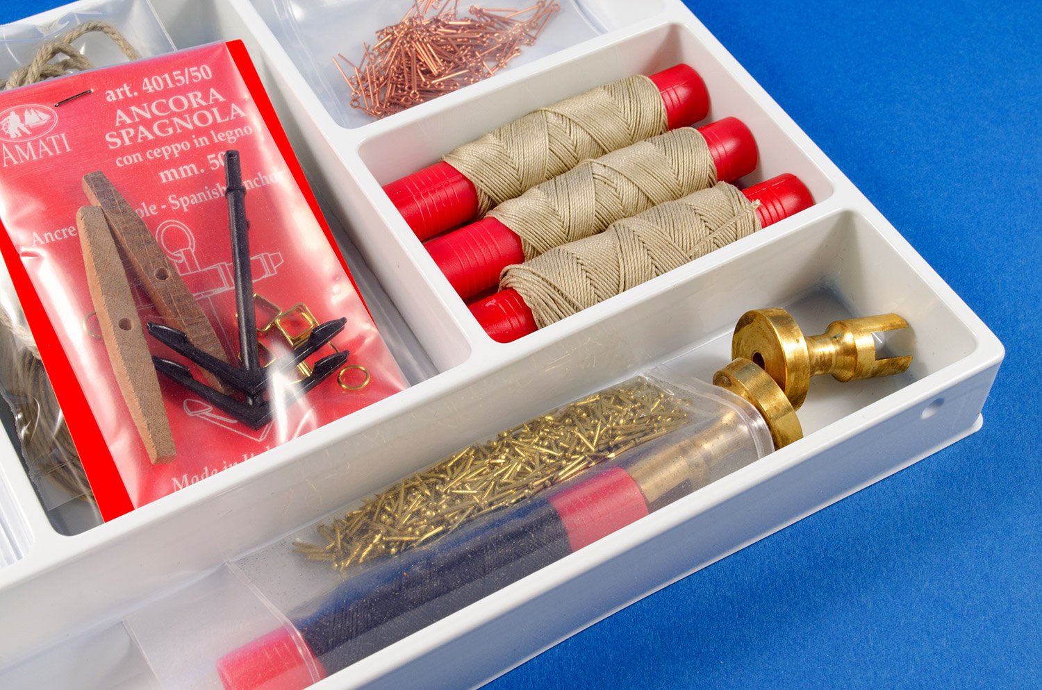
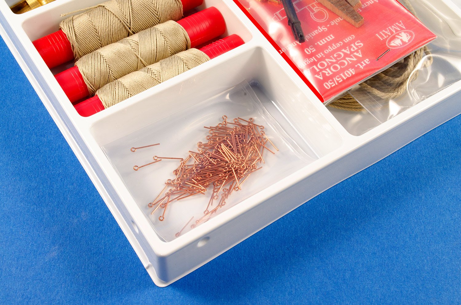
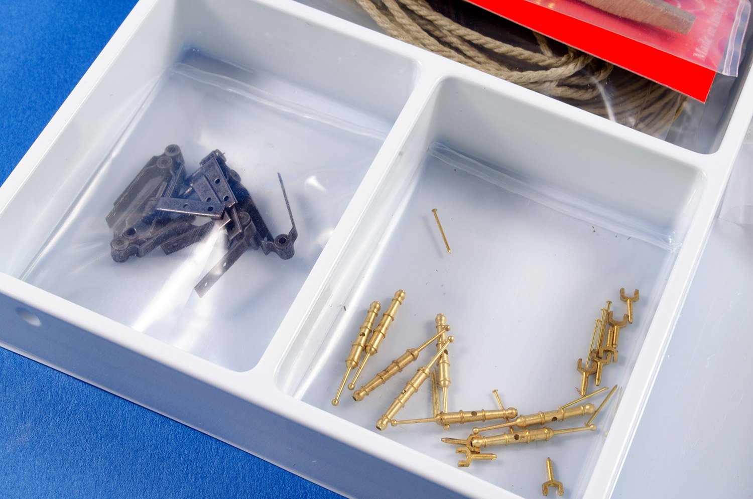
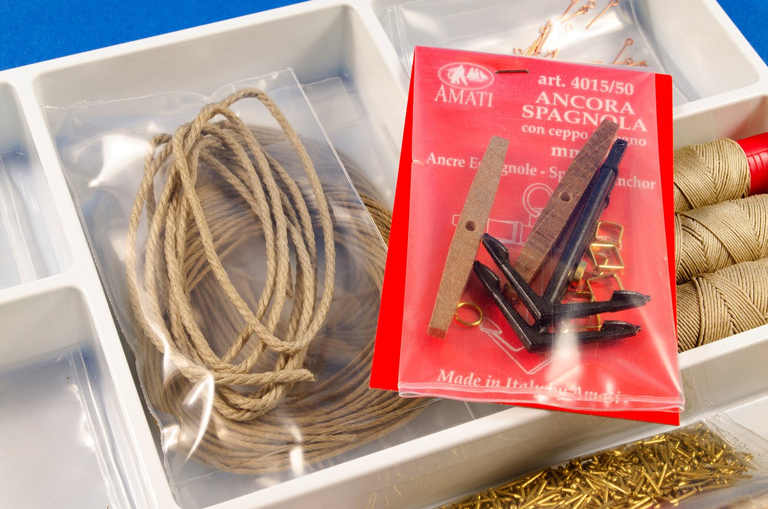
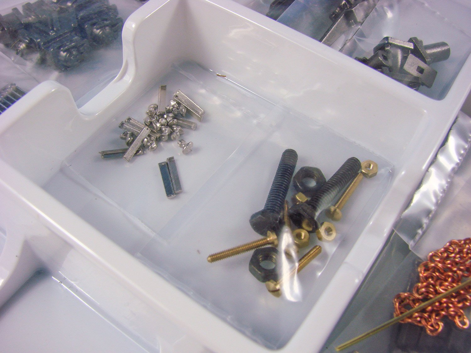
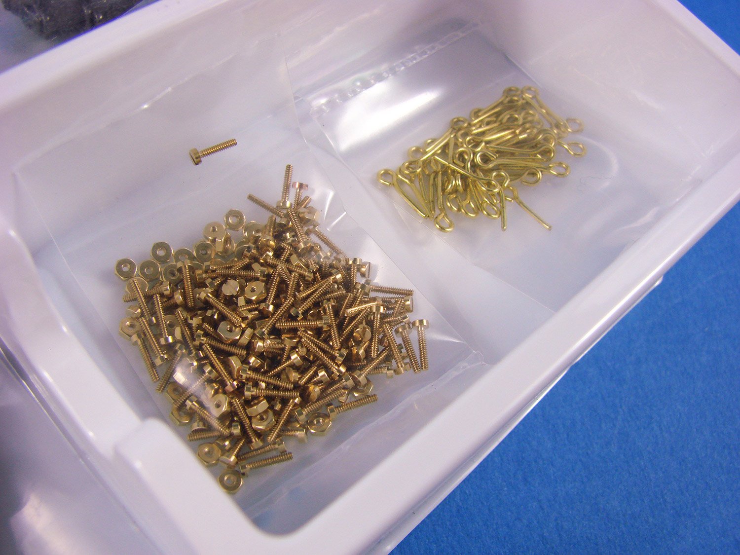
The second box contains rope, rigging cord, anchor set, culverins, pre-shaped rudder hinges, brass pedestals to mount the model to the base, brass pins, copper eyelets, etc.
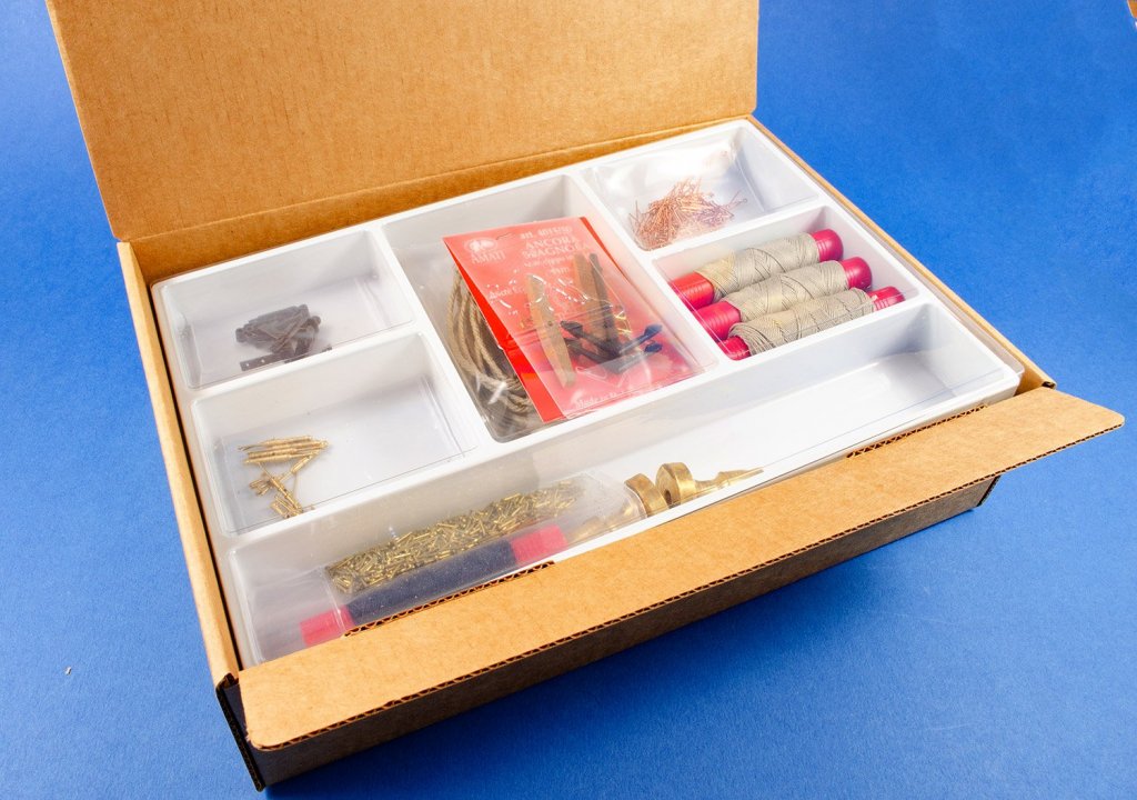


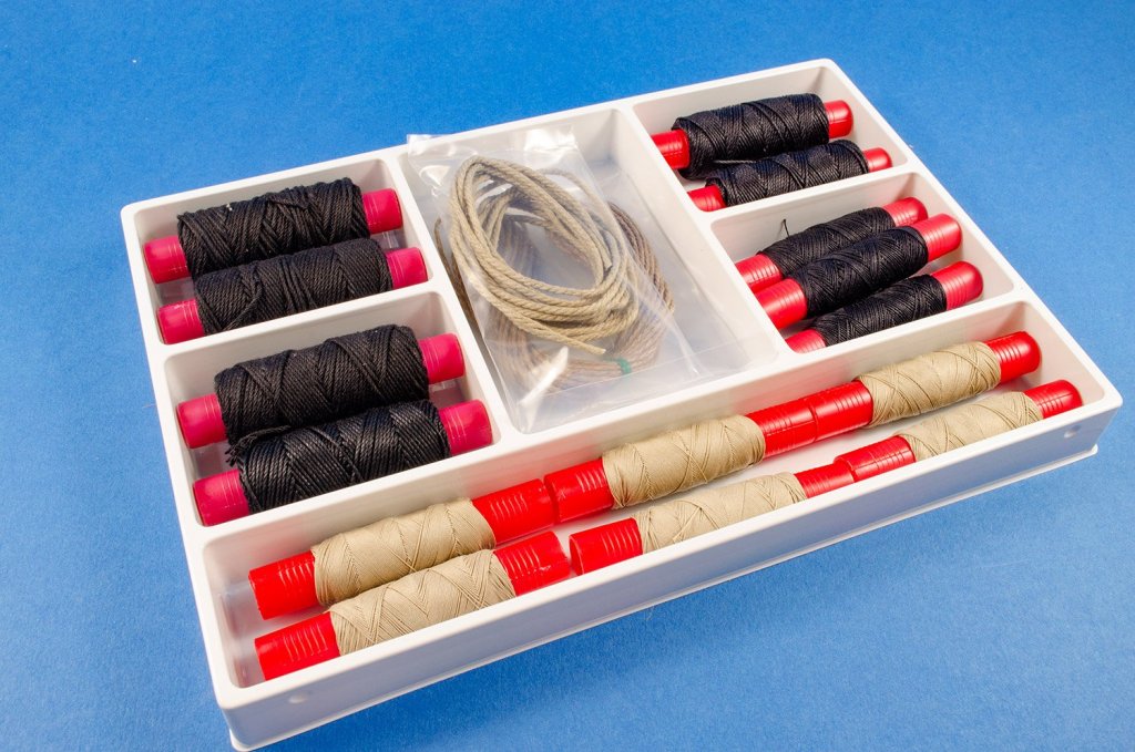
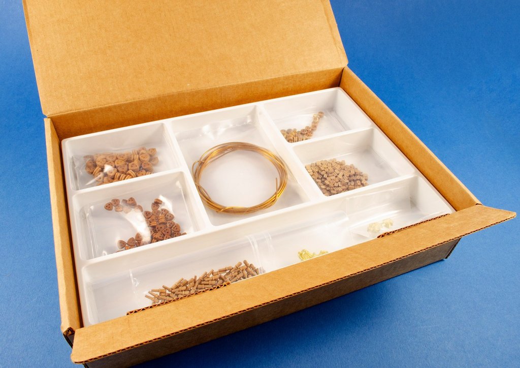
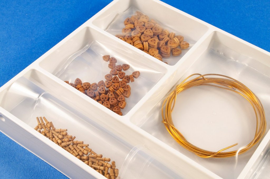
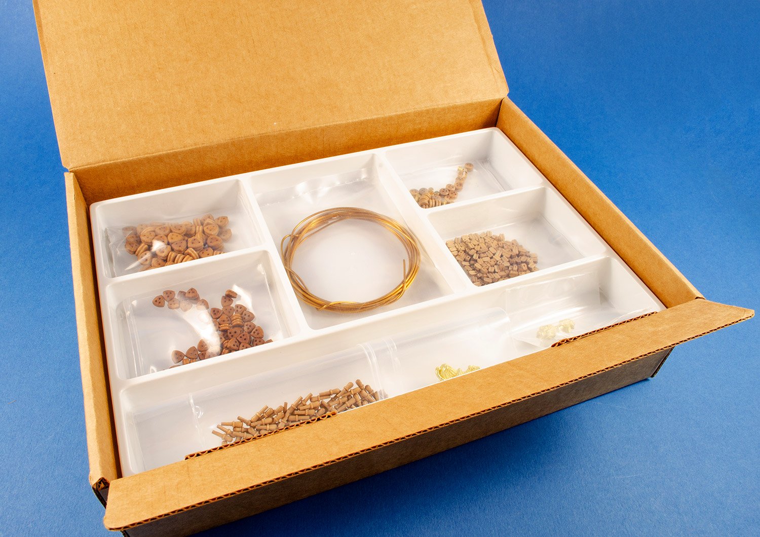
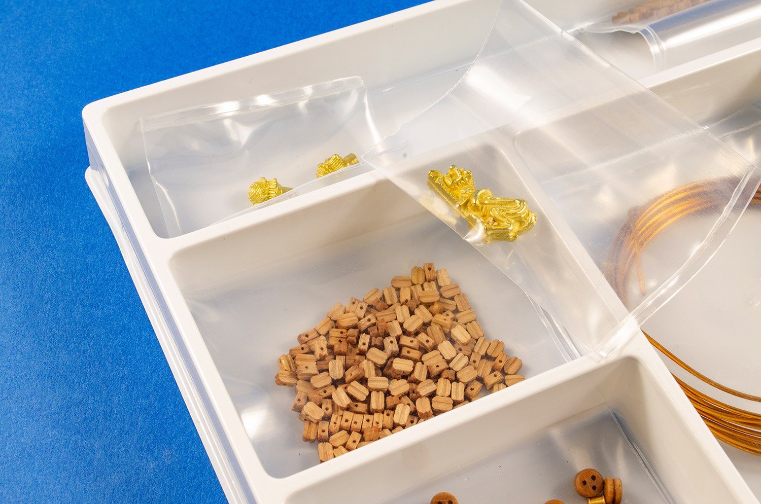
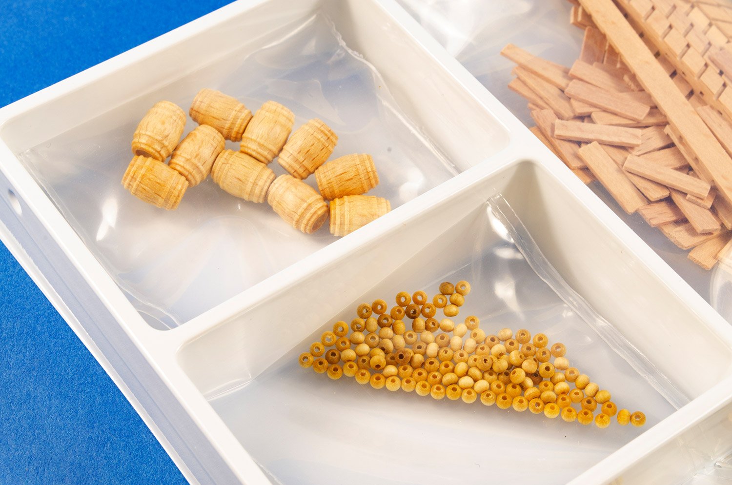
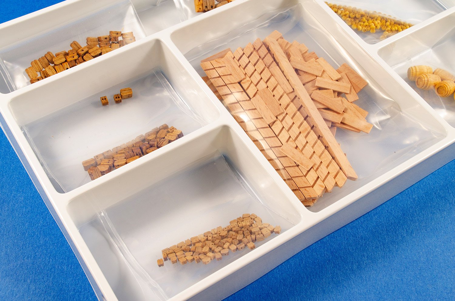
Our last box has more goodies for the rigging, such as various-sized deadeyes, blocks and belaying pins etc. You will also find here some brass wire, cast figurehead ornamentation, barrels, stair kit, and parrel beads. All components are securely bagged within their own compartments.

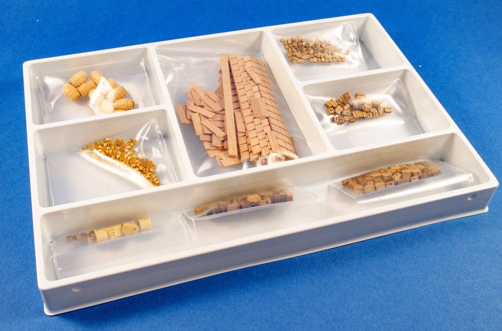

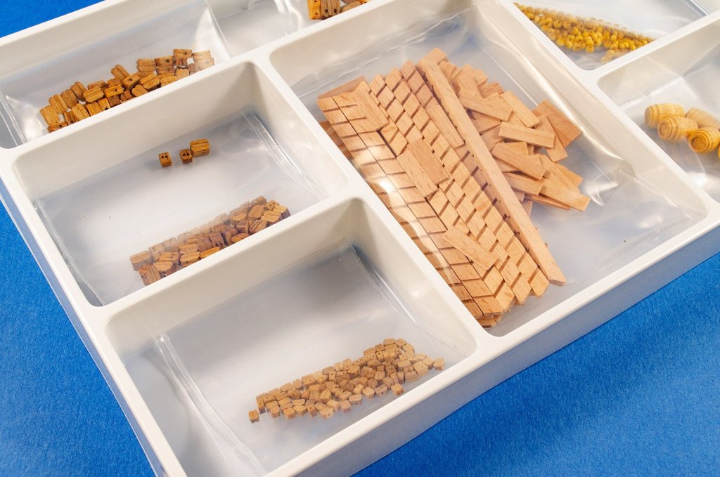
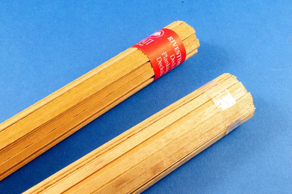
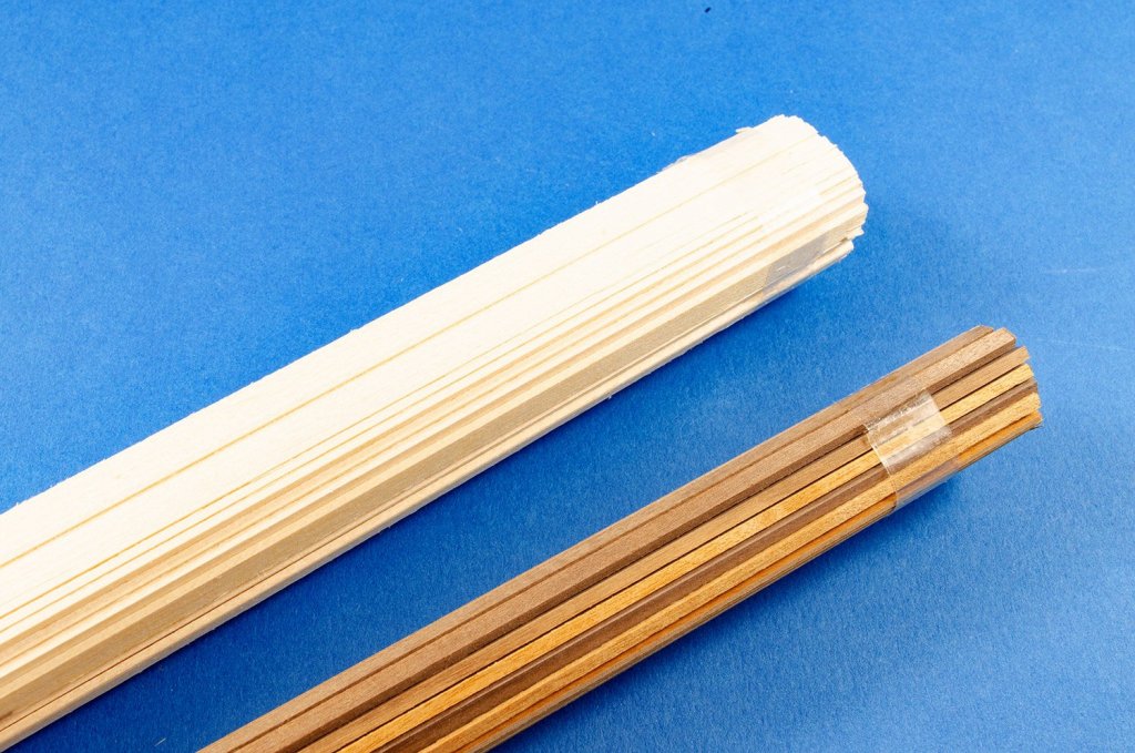
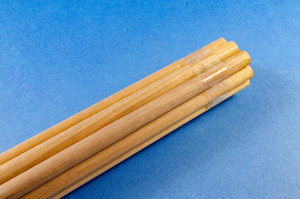
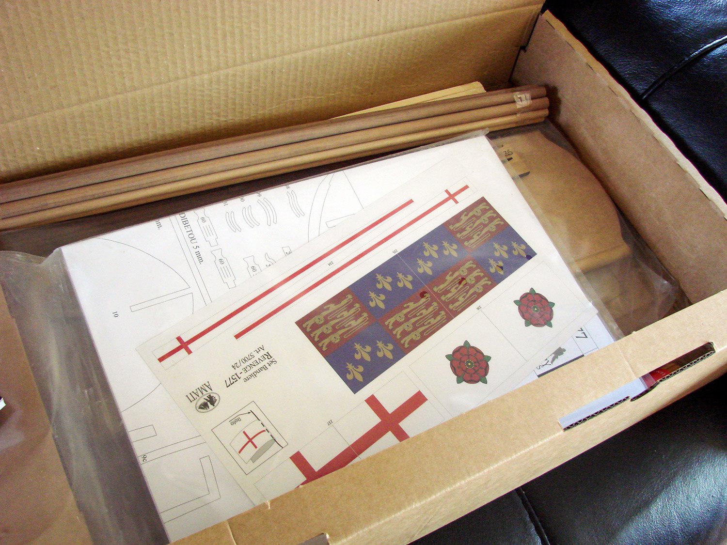
Amati include some nice timbers in their releases, and here we have bundles of strip wood for the double planked hull (lime for first plank), deck etc. The deck planking actually has a paper identifying tag. Dowel is of walnut, and again, quality is excellent.
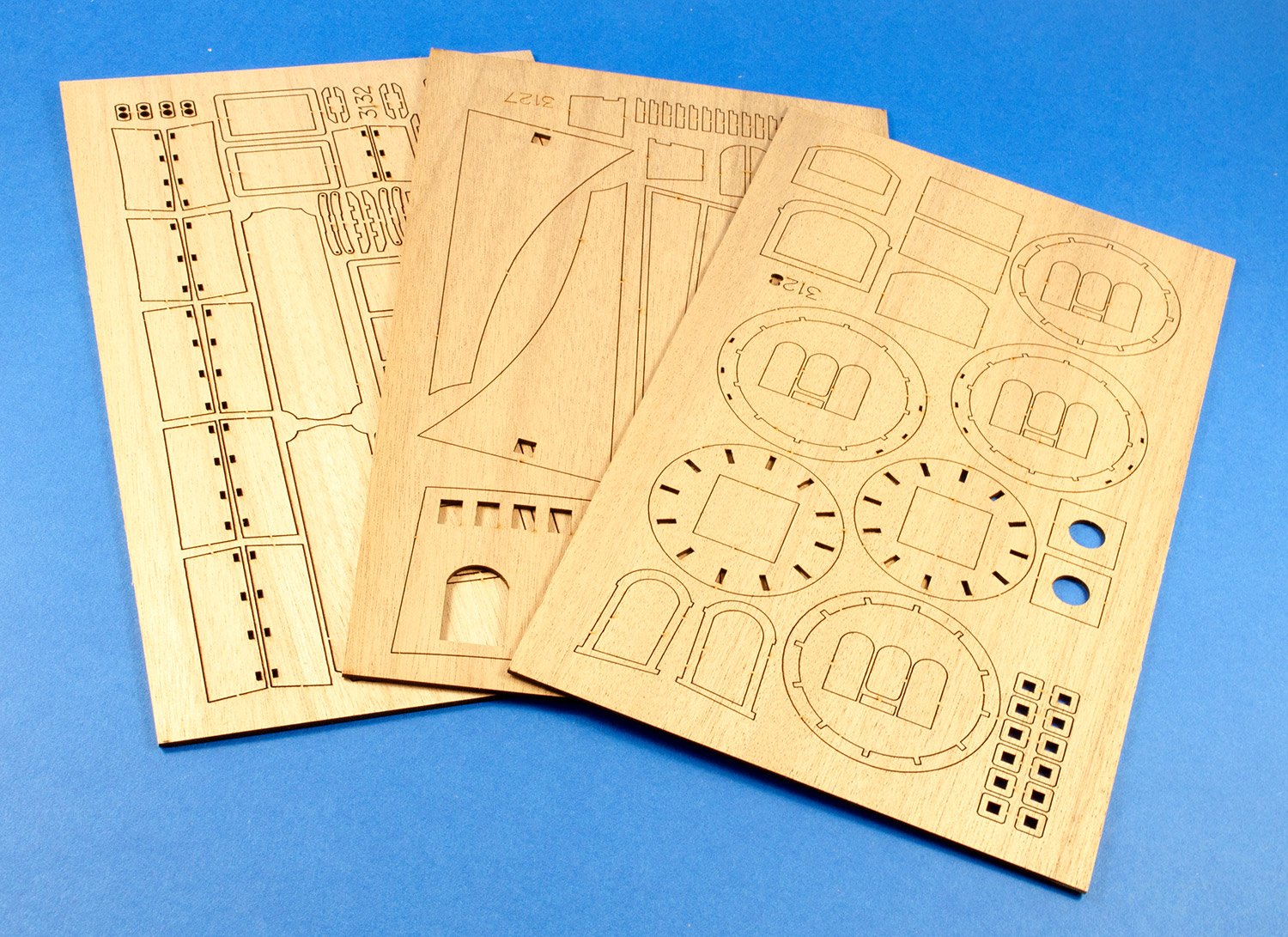
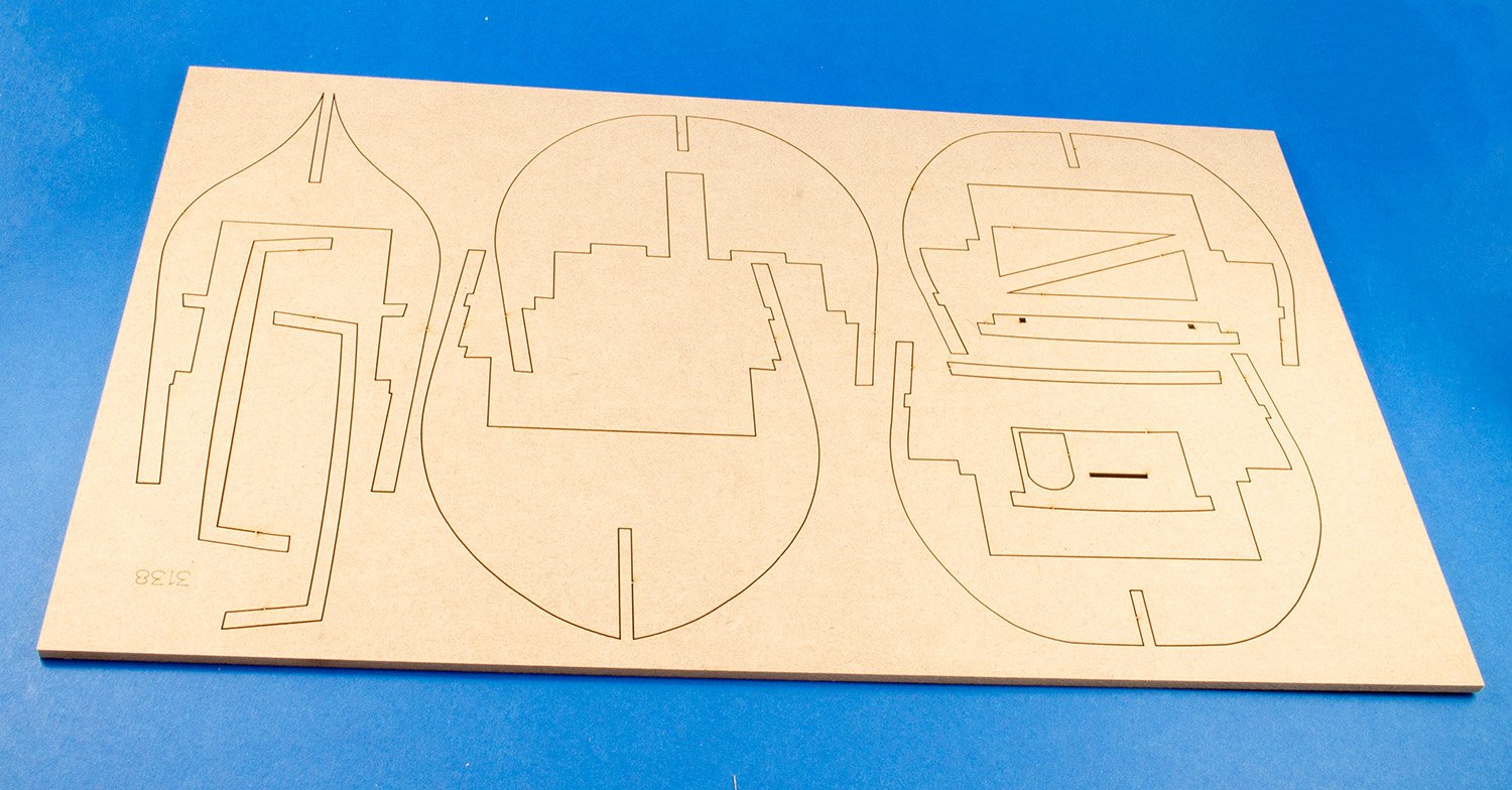
A single sheet of laser-cut ply contains the channels and rear gallery doors etc, and a further three sheets of ply are taken over with more channels, facings for the cabin access bulkhead, and the unusual Tudor circular mast-tops.
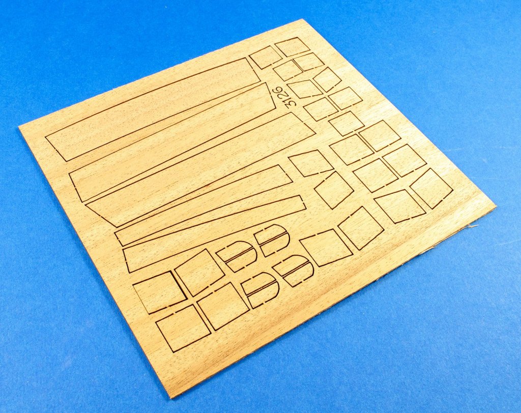

Two small sheets of wood (not ply) contain rudder and windlass parts, chain knees, and the lower keel. All parts are finely cut and will of course require any charring to be removed, although this is a fairly quick job.
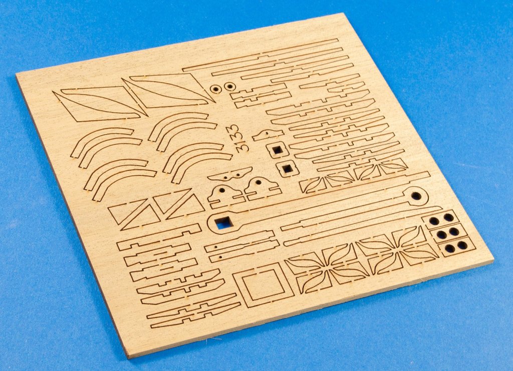

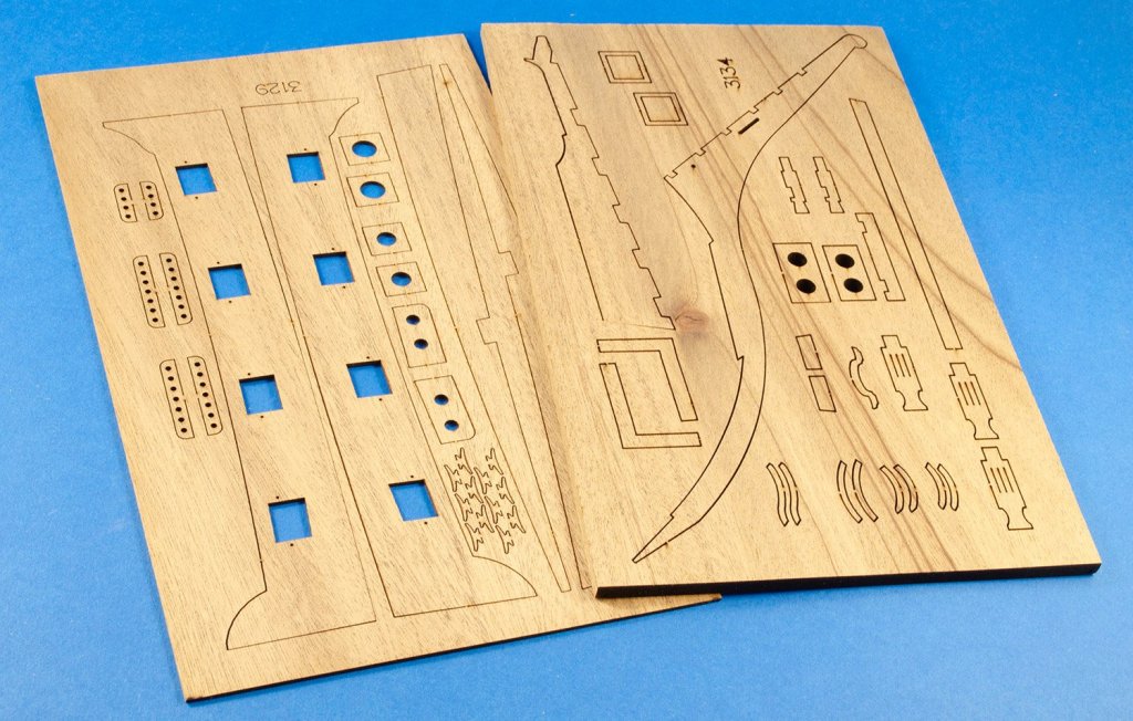
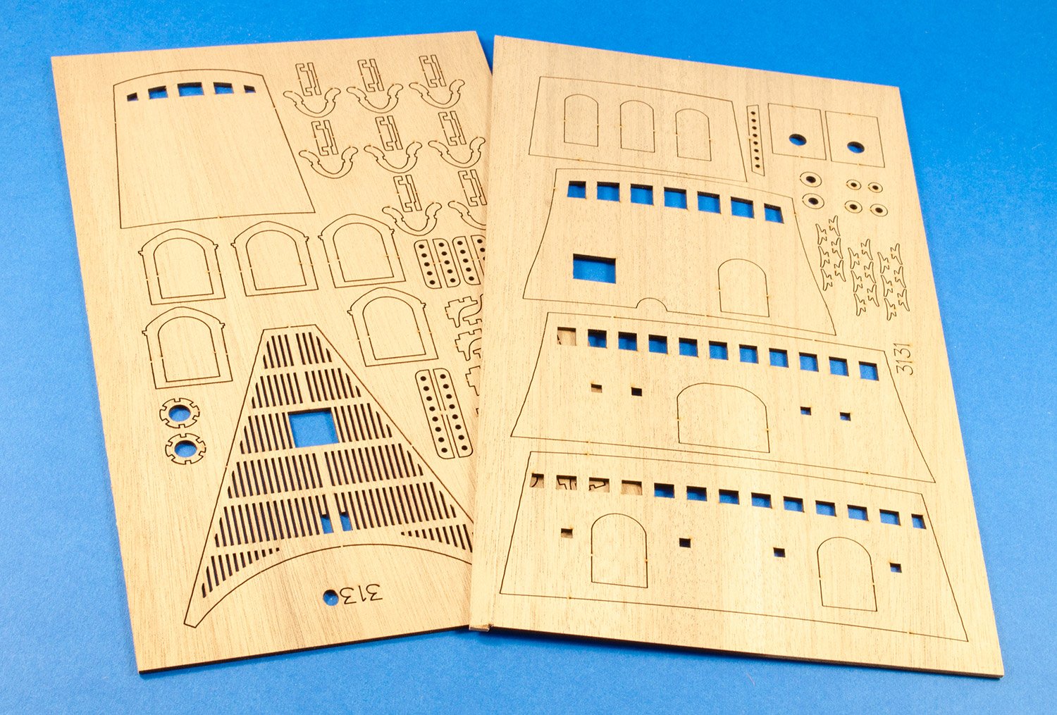
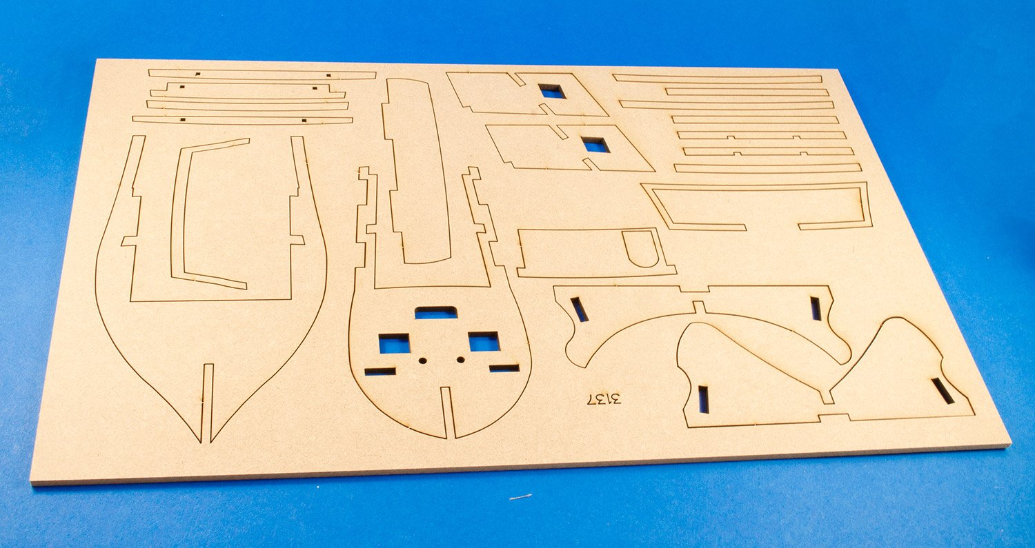
Two reasonably large sheets of ply contain the beak grate platform, transom, and more bulkhead walls with pre-cut windows and doors. These will of course be individually planked, and various timber fittings and rails added to them. Smaller parts can be found here too, such as cannon shot garlands and rigging cleats.

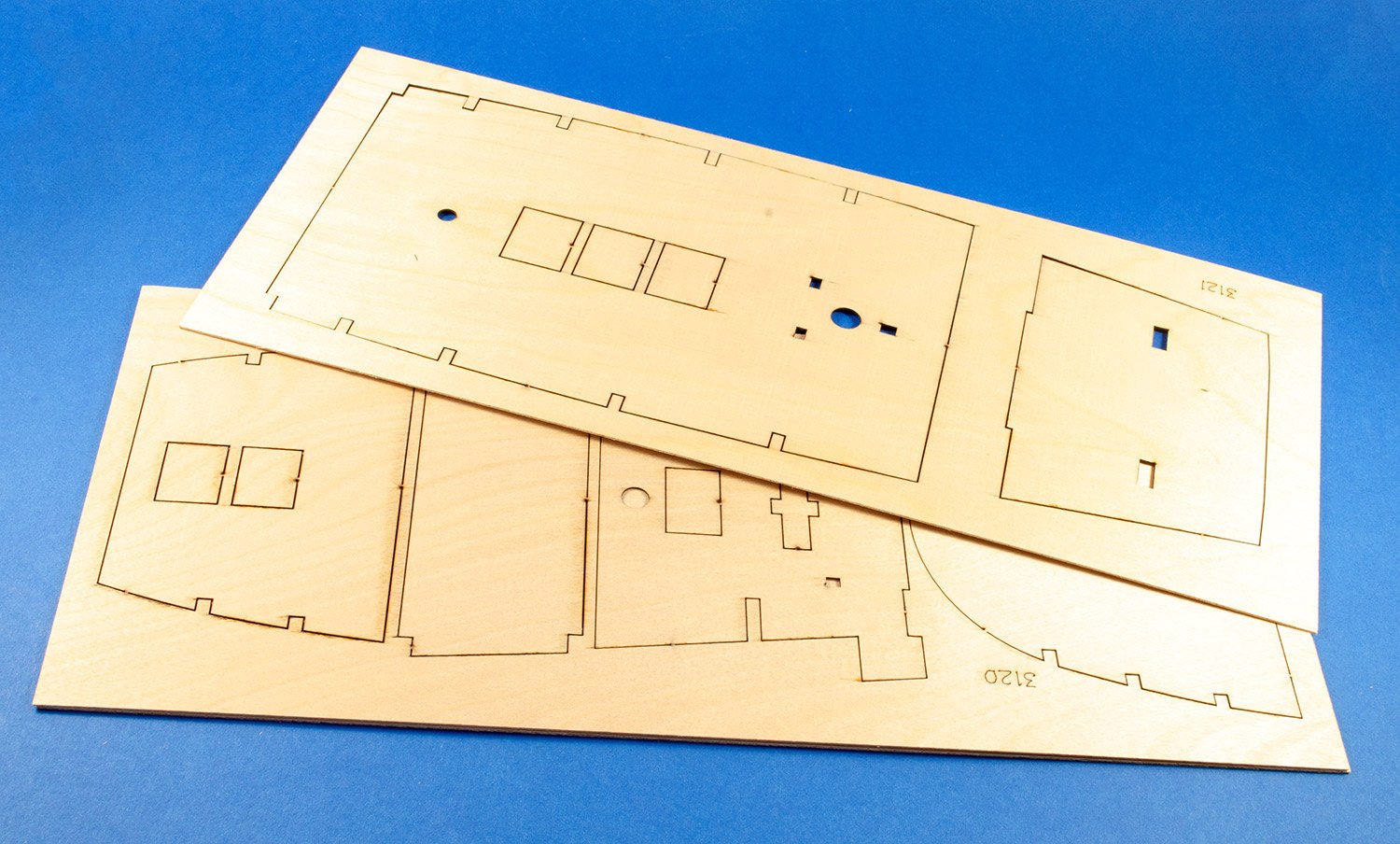
A further two thick ply sheets hold parts for the various decks, with the exception for the lowest main deck.

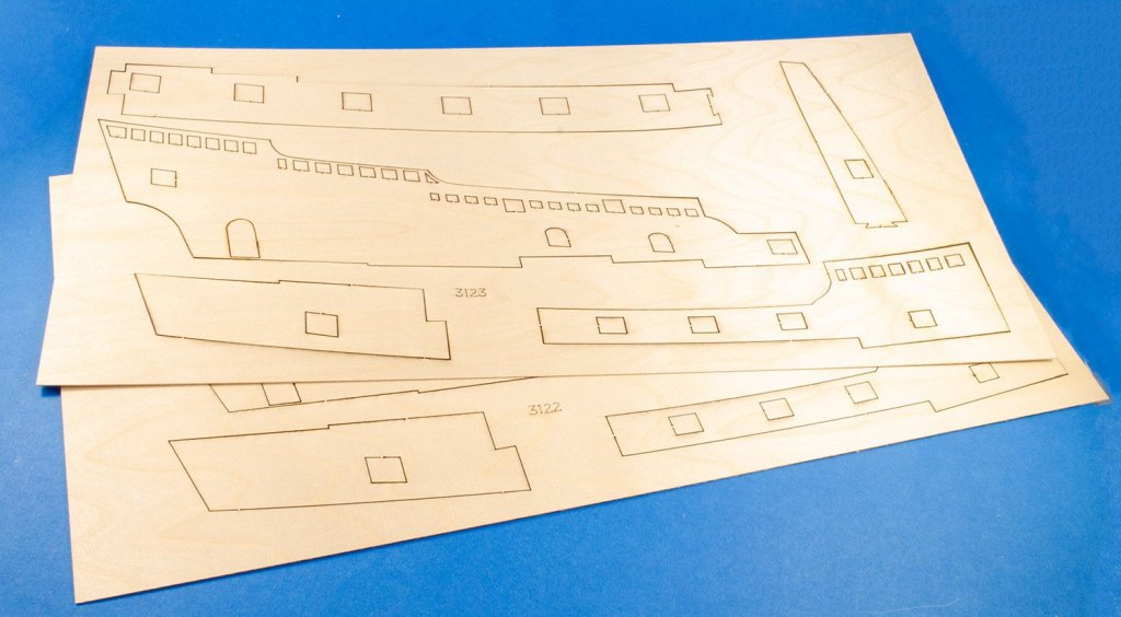
The largest ply sheets are fairly thin and for good reason, as they contain the upper bulwarks and sides with the gun port positions pre-cut. These will need to conform to the concave curvature of the hull at that point, hence the thinness of them. They are also joined by an interlocking pattern, so you achieve the correct placement of them.
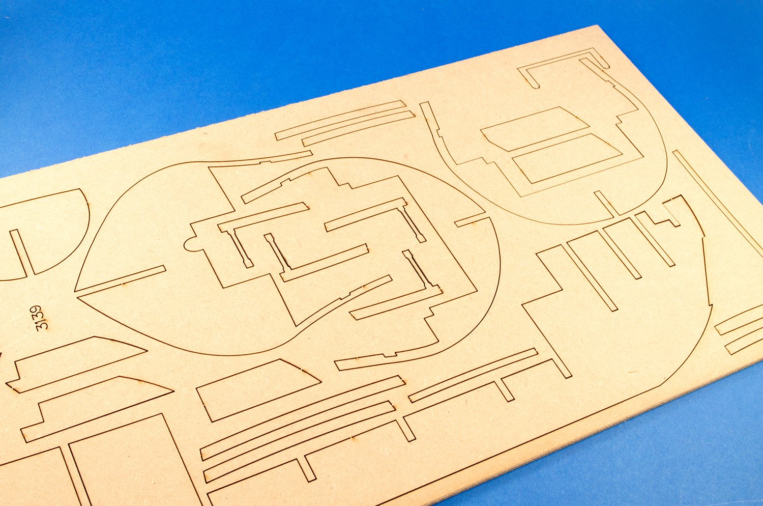
More laser-cut ply here, with garlands, rudder and forward bow keel section etc.
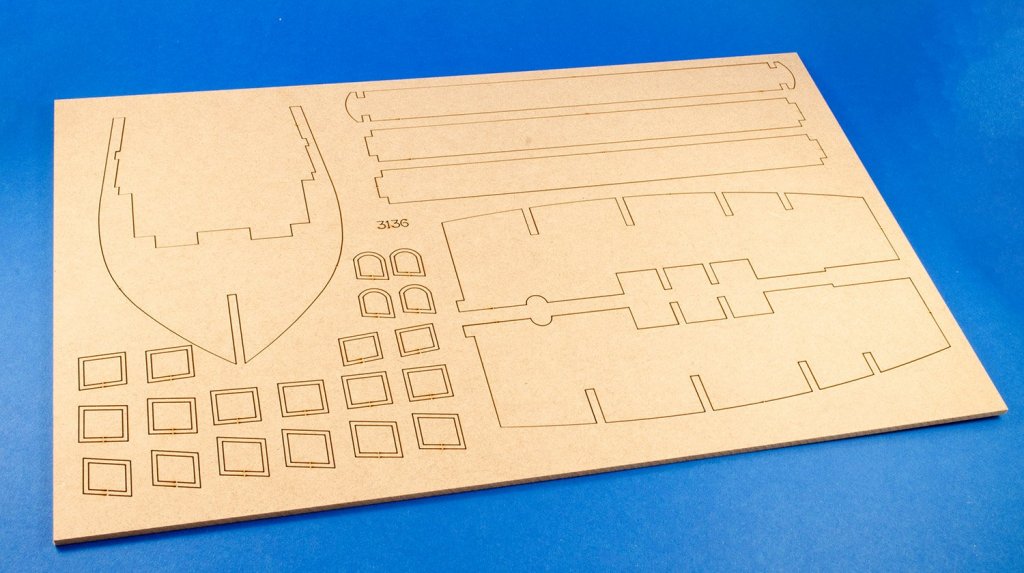
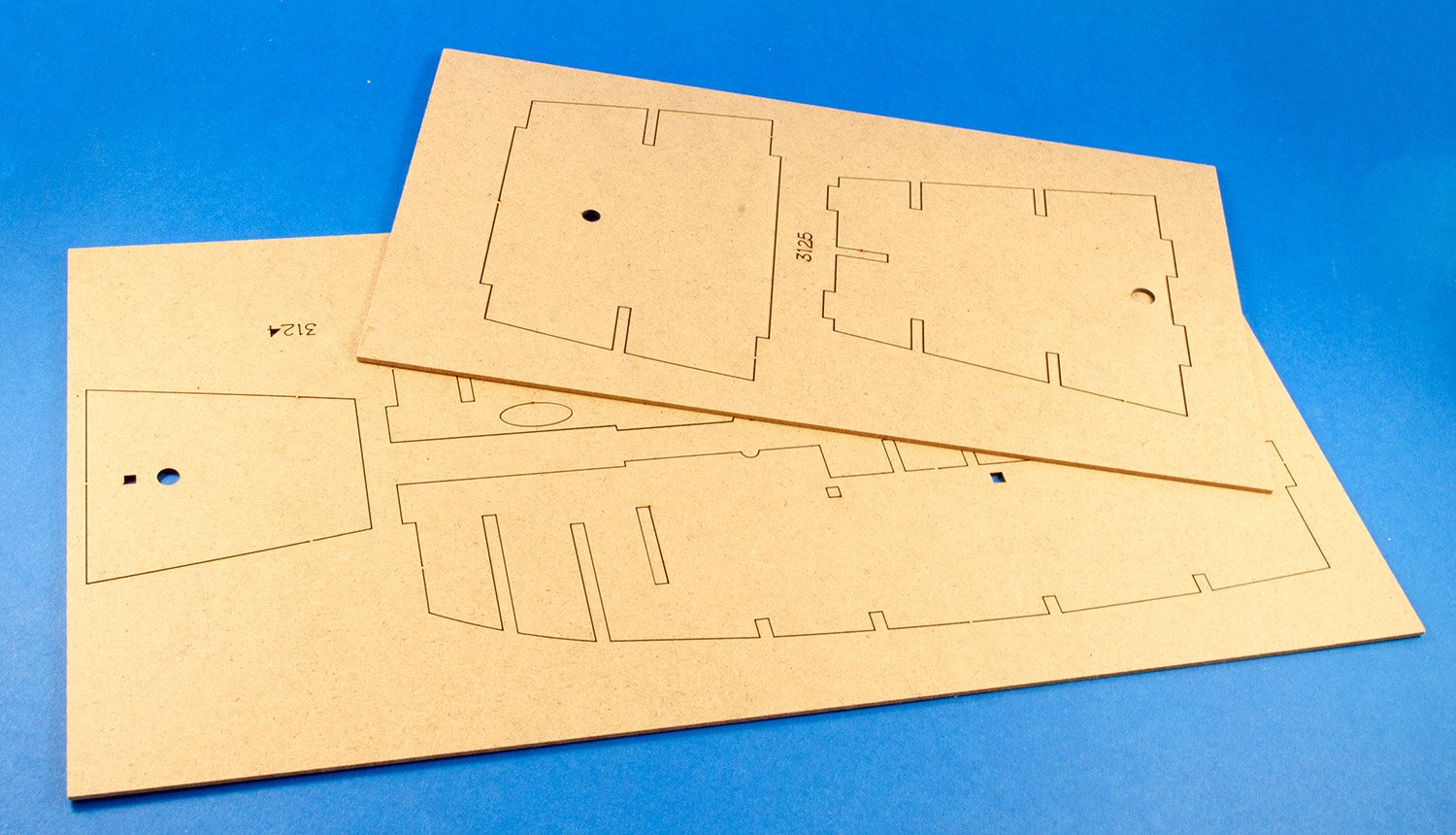
Five MDF sheets contain all main constructional components, such as the false keel, bulkheads, lowest main deck, deck beams etc. Whilst the curved sides of the bulkheads look very fragile, several builds here on MSW show that there shouldn’t be any real concern as long as you exercise some care and attention.


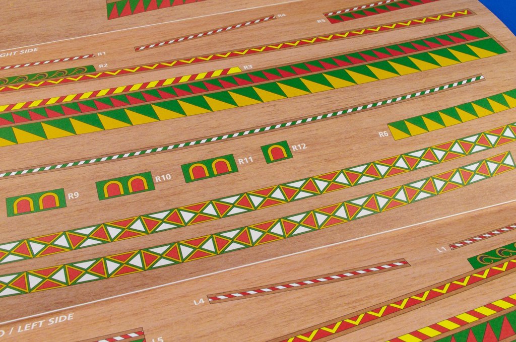
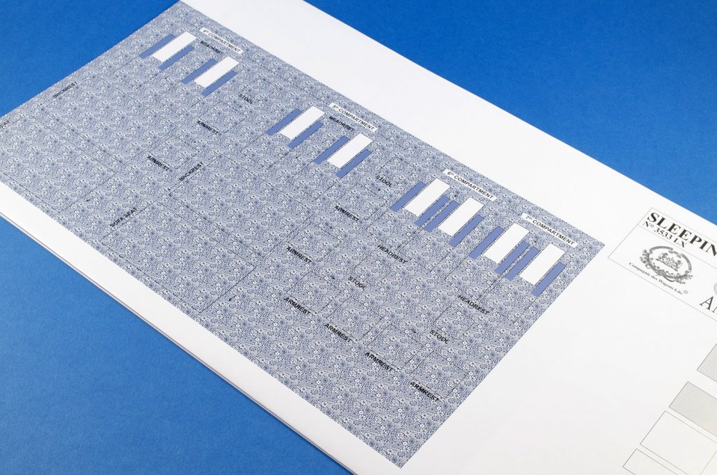
You will doubtless have noticed that instead of the carved embellishments we see on later and Spanish vessels etc, this Tudor warship has coloured panels along the outer bulwarks etc. Thankfully, you won’t need to paint these at all as they are provided as pre-printed items. Now, the paper they are printed on is heavier than writing paper and is of a type which means that the printing won’t fade. I’m presuming it’s all acid-free paper etc too. Printing is super-high quality and against a wooden texture background for a reason I can’t fathom. Still, these look amazing when added and really bring the vessel to life. All paper parts are numbered, and sections of the sheet listed as for right/left side.
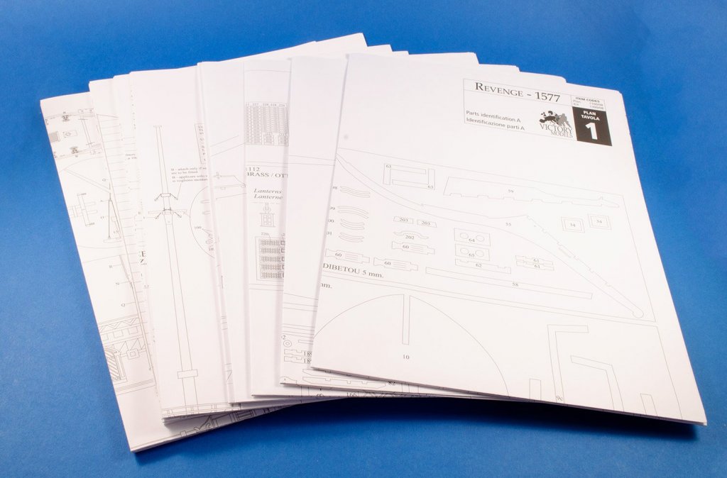
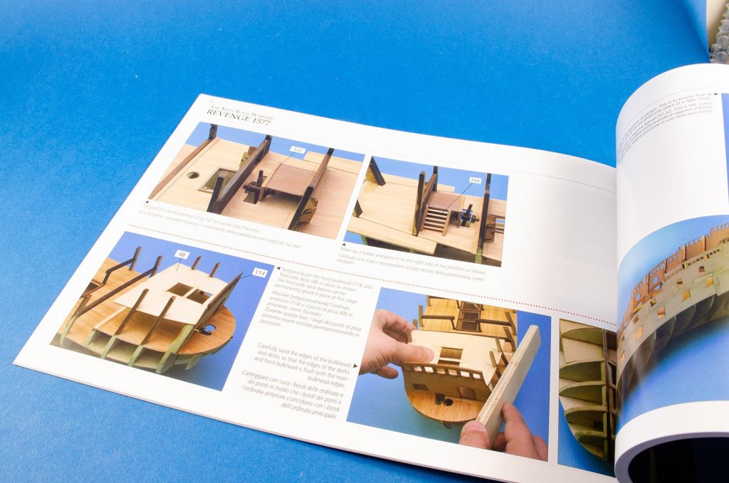
There are 20 sheets of plans for this model, but as well as parts maps which cover several pages, the remainder generally looks to contain information for masting and rigging the ship, plus adding the sails, if you wish. There are other illustrations of the model too, but the hull and fitting out is mostly done using the instruction manual.
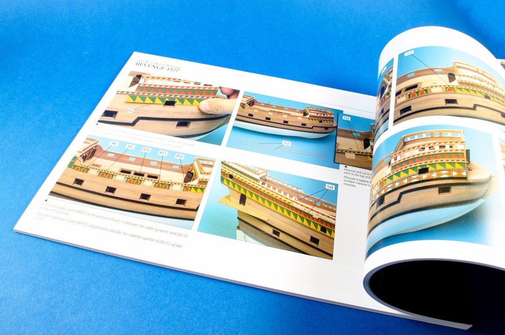
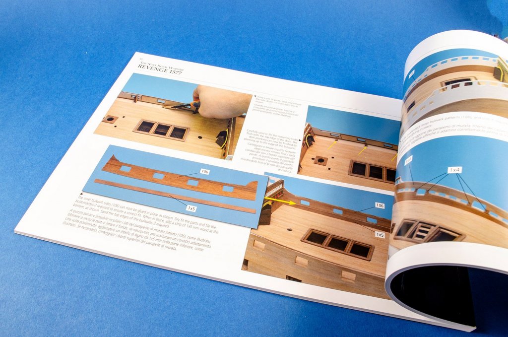
When it comes to instruction manuals, Amati really do go to town. Their latest releases, such as the Orient Express Sleeping Car, contain glossy, full-colour photographic instruction booklets with clear English text (Italian also shown). Each stage of the build is clearly shown, and nothing should be ambiguous with this particular presentation.

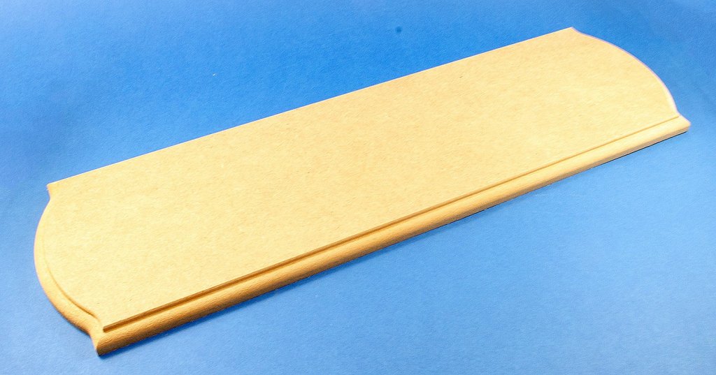
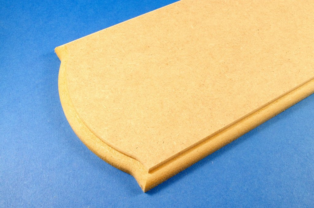
Lastly, unlike most model kits, this one does include a base, as previously mentioned. This is machined from MDF and will need sealing and rubbing back before painting. The edges of this are profiled too. With the brass pedestals and name plates, this should look very nice when complete.
Conclusion
This model was released in 2015 and comes from the stable of those designed by Chris Watton. Unlike his Nelson’s-era kits, this little gem doesn’t seem to get the recognition is deserves, although as I say, we do have some logs of the build here on MSW. Tudor warships, for me, really are beautiful in their style and execution. I’m a big fan of the Mary Rose (for which I also have a kit), but this particular vessel is more ornate than the Mary Rose and has the galleon-style features that we expect from a ship of this period. Timber quality is excellent, as are the various fittings, and of course, the instructions means that you shouldn’t go wrong during your build. The pre-cut gun ports and jigsaw bulwarks will also ensure a trouble-free project. Cornwall Model Boats currently lists this model for £364.99, and I think that represents really good value for money for a ship of this size (Length: 885mm, Width: 380mm, Height: 655mm)My sincere thanks to Amati for sending out this kit for review here on Model Ship World. To purchase, head over to your favourite Amati-stockist of online retailer)

- Rik Thistle, JpR62, MEDDO and 15 others
-
18
-
-
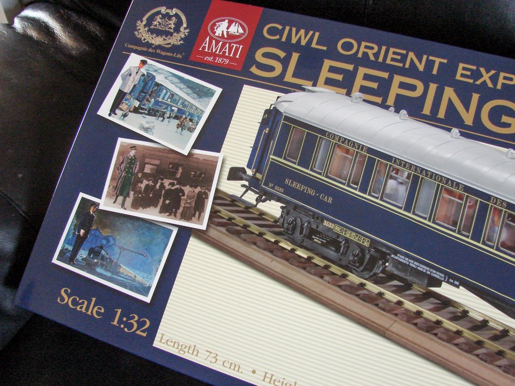
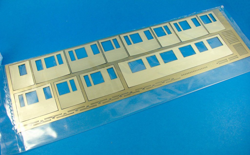
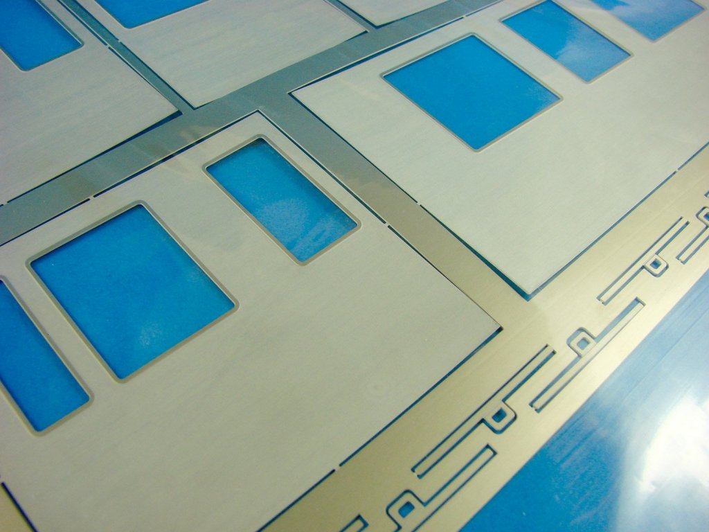
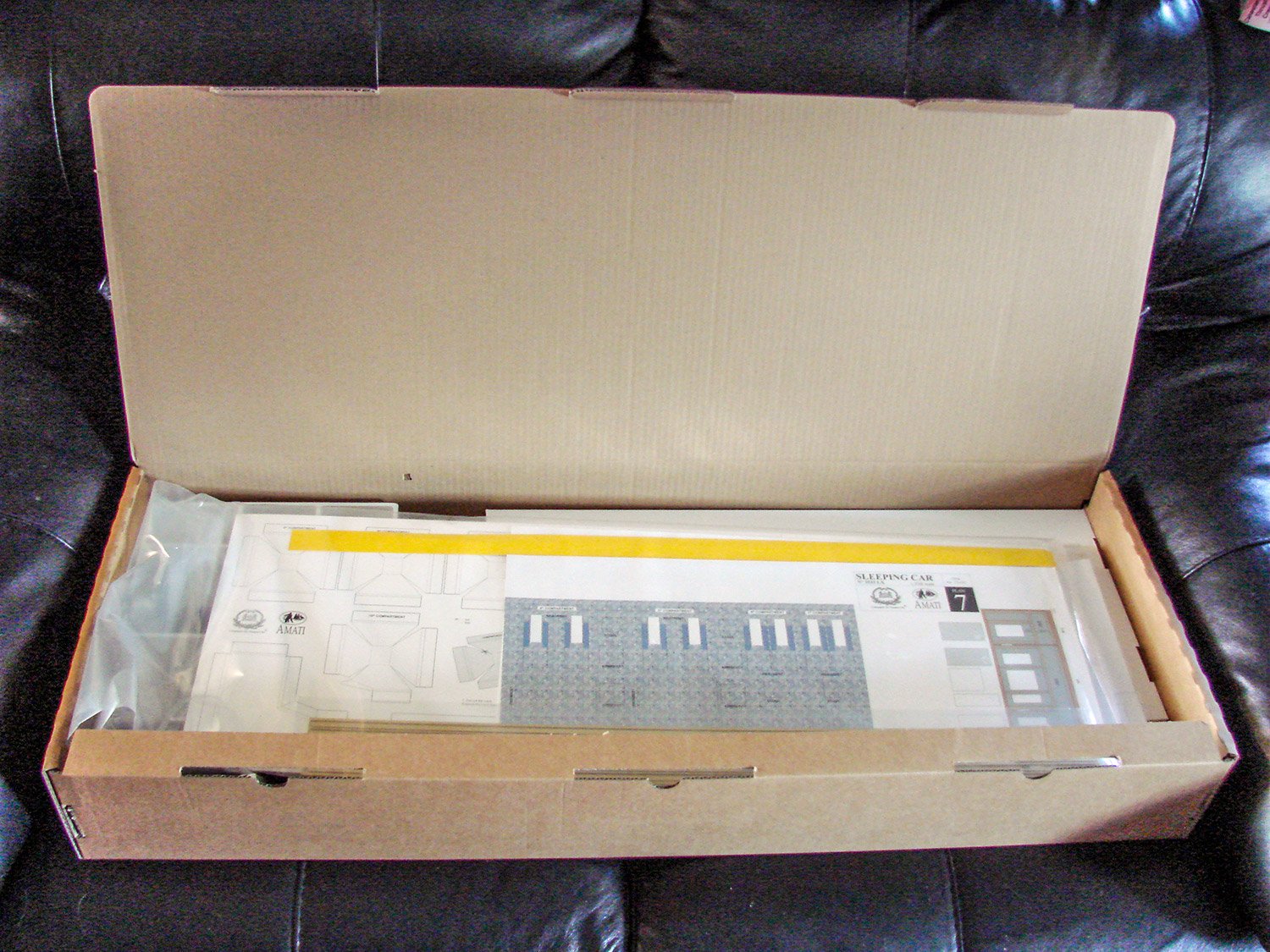
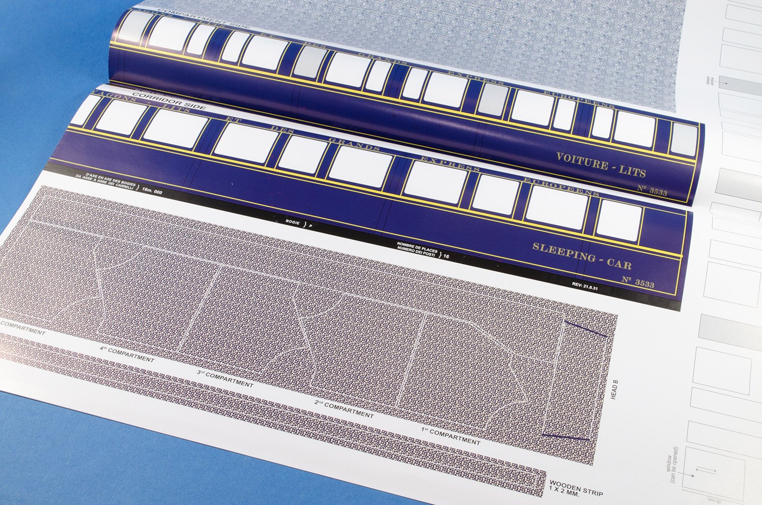
1/32 1929 Orient Express Sleeping Car No.3533 LX
Amati
Catalogue # 1714/01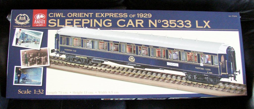
Ok, I know this isn't a ship kit, but it is very much a wood and photo-etch model, and from Amati. I hope you enjoy!
The Orient Expresswas a long-distance passenger train service created in 1883 by Compagnie Internationale des Wagons-Lits (CIWL). The route and rolling stock of the Orient Express changed many times. Several routes in the past concurrently used the Orient Express name, or slight variations. Although the original Orient Express was simply a normal international railway service, the name became synonymous with intrigue and luxury travel. The two city names most prominently associated with the Orient Express are Paris and Constantinople (Istanbul) the original endpoints of the timetabled service. The Orient Express was a showcase of luxury and comfort at a time when travelling was still rough and dangerous. On June 5, 1883, the first Express d'Orient left Paris for Vienna. Vienna remained the terminus until October 4, 1883. The train was officially renamed Orient Express in 1891. In 1889, the train's eastern terminus became Varna in Bulgaria, where passengers could take a ship to Constantinople. On June 1, 1889, the first direct train to Istanbul left Paris (Gare de l'Est). Istanbul remained its easternmost stop until May 19, 1977.
1929 Sleeping Car shown from 4.00minutes (new upholstery)The onset of World War I in 1914 saw Orient Express services suspended. They resumed at the end of hostilities in 1918, and in 1919 the opening of the Simplon Tunnel allowed the introduction of a more southerly route via Milan, Venice, and Trieste. The 1930s saw the Orient Express services at its most popular, with three parallel services running: the Orient Express, the Simplon Orient Express, and also the Arlberg Orient Express, which ran via Zürich and Innsbruck to Budapest, with sleeper cars running onwards from there to Bucharest and Athens. During this time, the Orient Express acquired its reputation for comfort and luxury, carrying sleeping-cars with permanent service and restaurant cars known for the quality of their cuisine. Royalty, nobles, diplomats, business people, and the bourgeoisie in general patronized it. Each of the Orient Express services also incorporated sleeping cars which had run from Calais to Paris, thus extending the service right from one edge of continental Europe to the other.
The kit
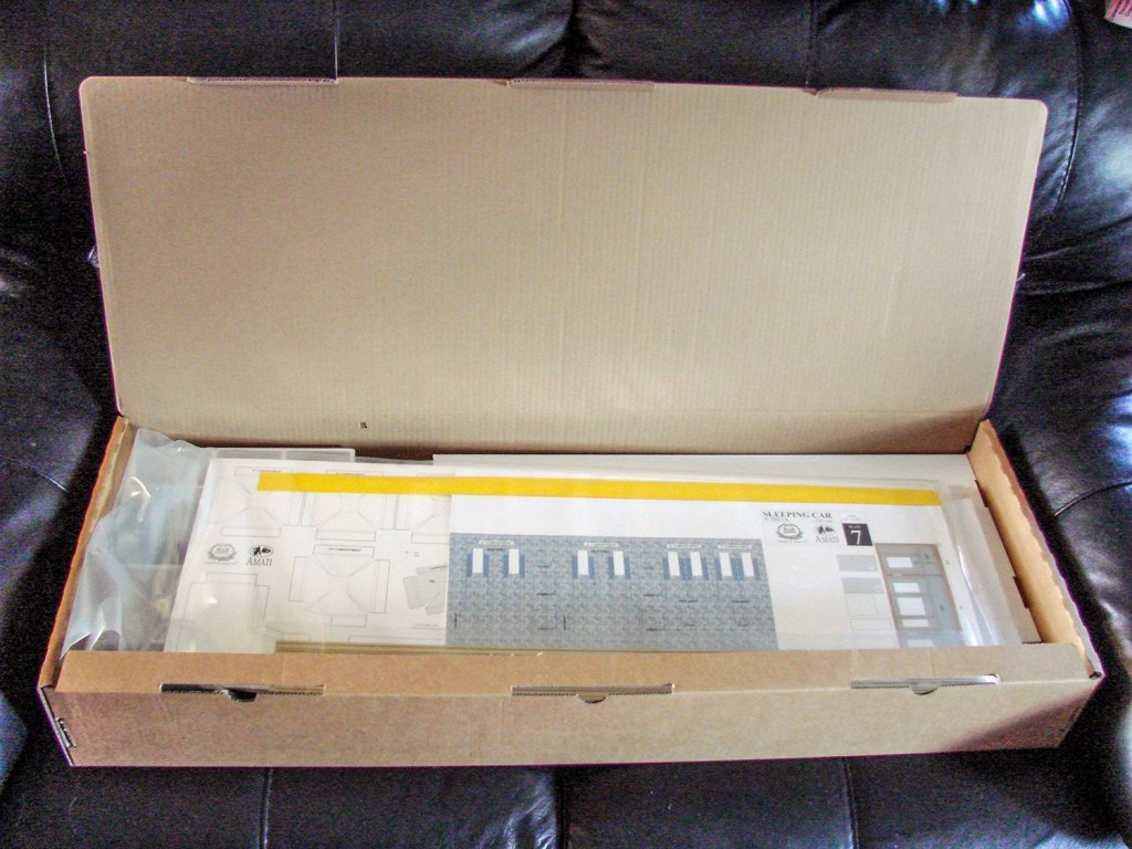

Amati had been publishing videos and photos of this then-upcoming kit on Facebook for a few months, and even though trains aren’t really my thing, this one looked intriguing with its 1920s/30s wooden opulence, so when Amati said they would ship one out to me to look at, that was very exciting. I knew this was going to me one large kit, but I had no idea! The model itself is 1/32 and the box is the same size as their1/72 HMS Vanguardthat I recently took a look at. Whilst the box doesn’t weigh as much as that kit, it’s certainly packed out with some heavy metal. The box lid itself is decorative, depicting the finished model and some period imagery. You will also note that this model has a section of track on which to display the sleeping car. Lifting off that large lid uncovers a complete box with a tabbed, lift up lid, adorned in the Amati logo as standard for these large releases.
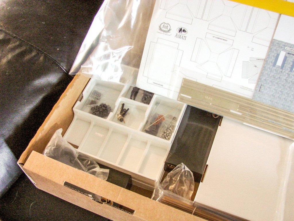
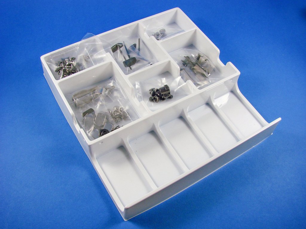
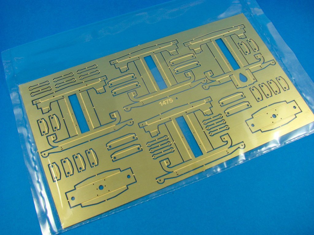
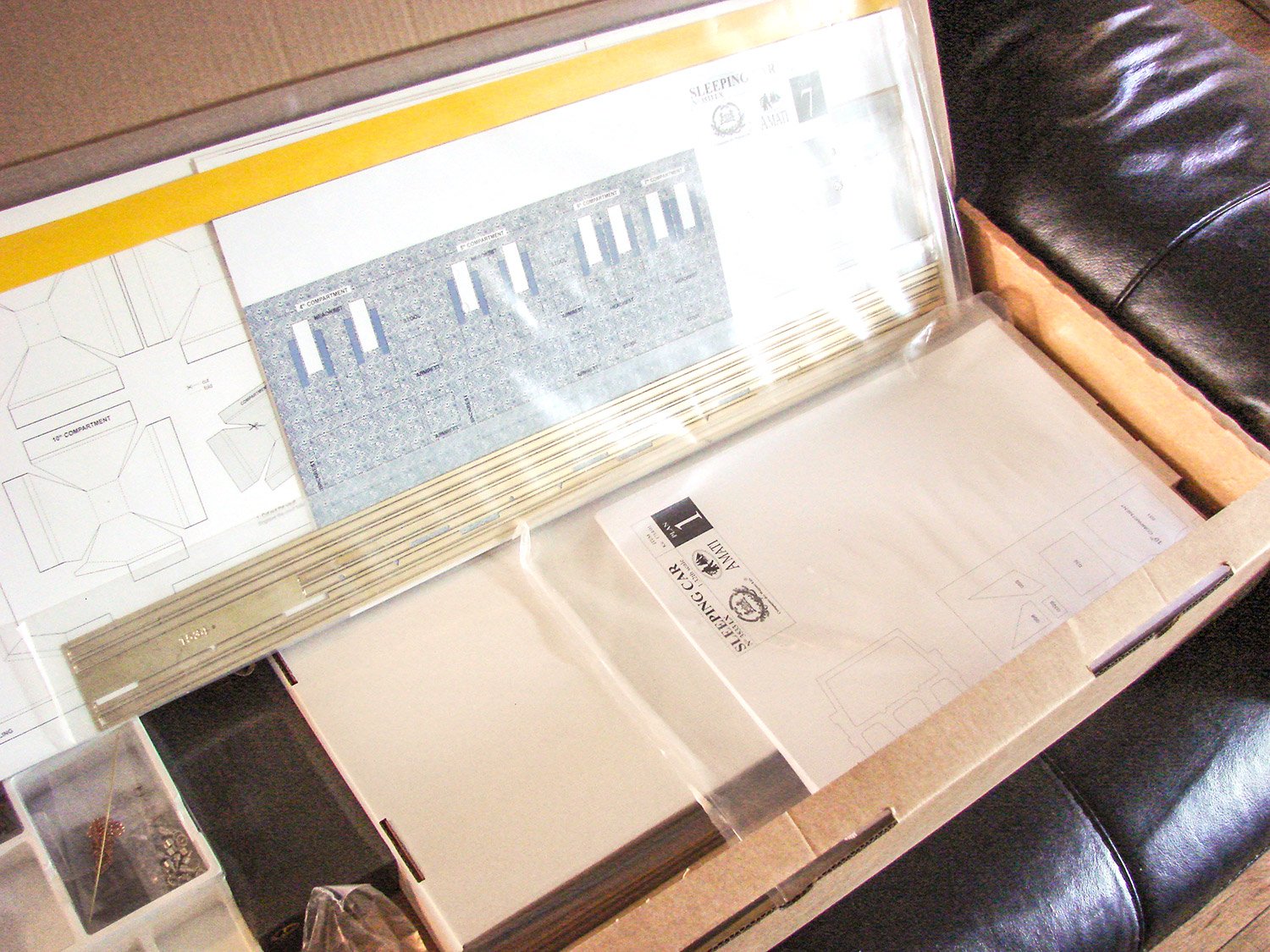
Chassis partsInside the box, we have plastic trays full of parts, two smaller Amati boxes, a large thick plastic sleeve with paper/wood/metal components, and sleeves full of timber strip and brass section strip. There are also a series of folded plans and TWO perfect-bound, full colour instruction books which look sumptuous. Lifting all of these out uncovers two card covers that when removed, show a whole swathe of photo-etch brass and nickel-silver sheets, and a bag holding three sections for the base onto which the rail tracks and sleepers will mount.
Amati’s 1/32 Orient Express Sleeping Car kit consists of:
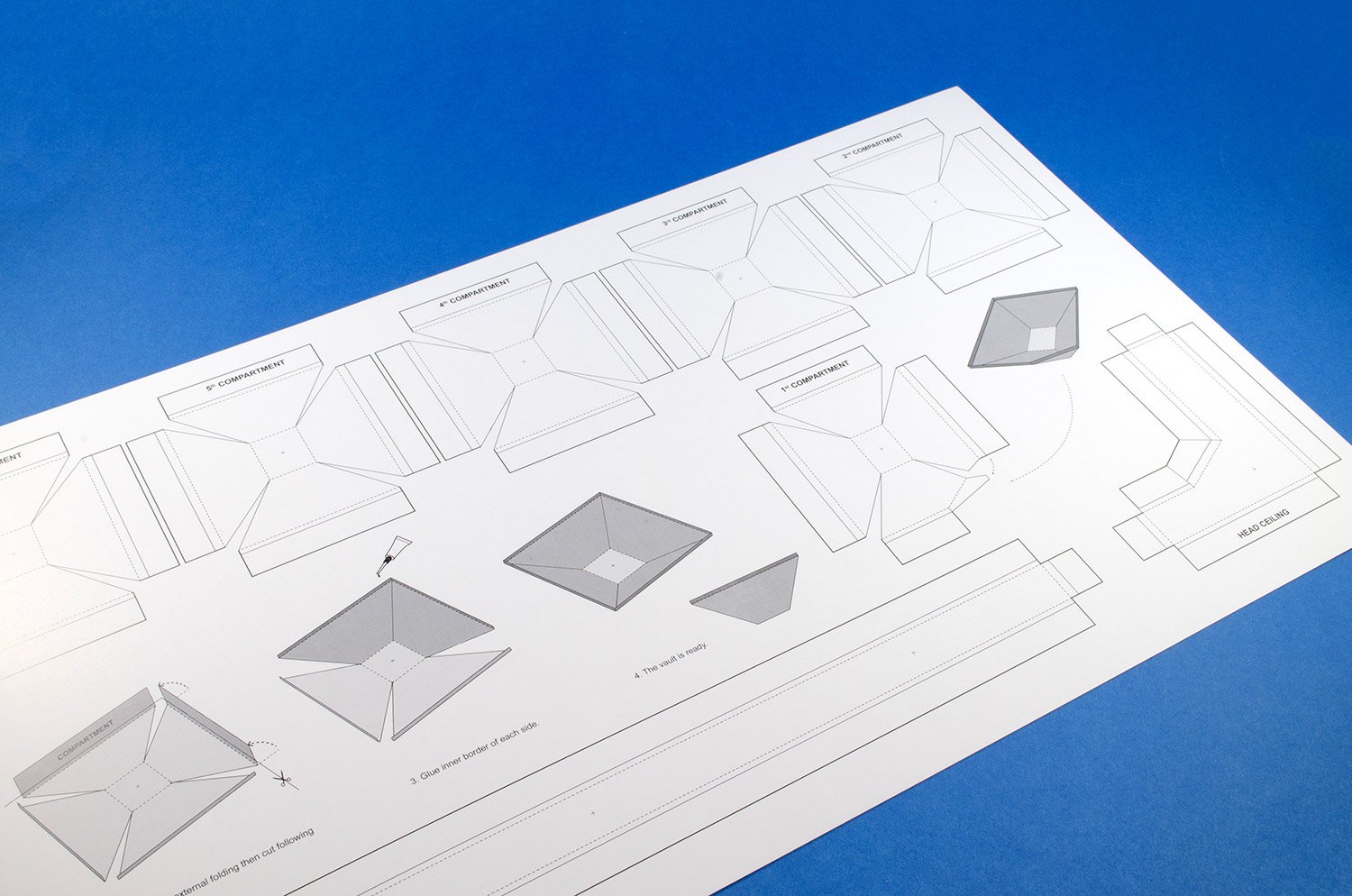
- 1 x gloss card for carriage ceiling mouldings
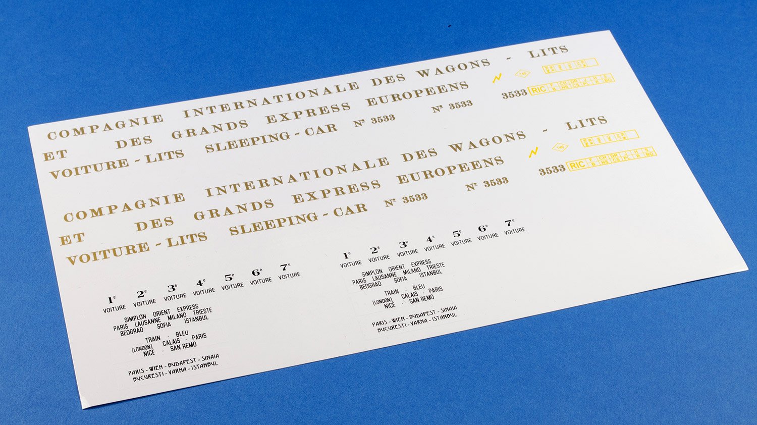
- 1 x decal sheet for carriage signwriting and stencils
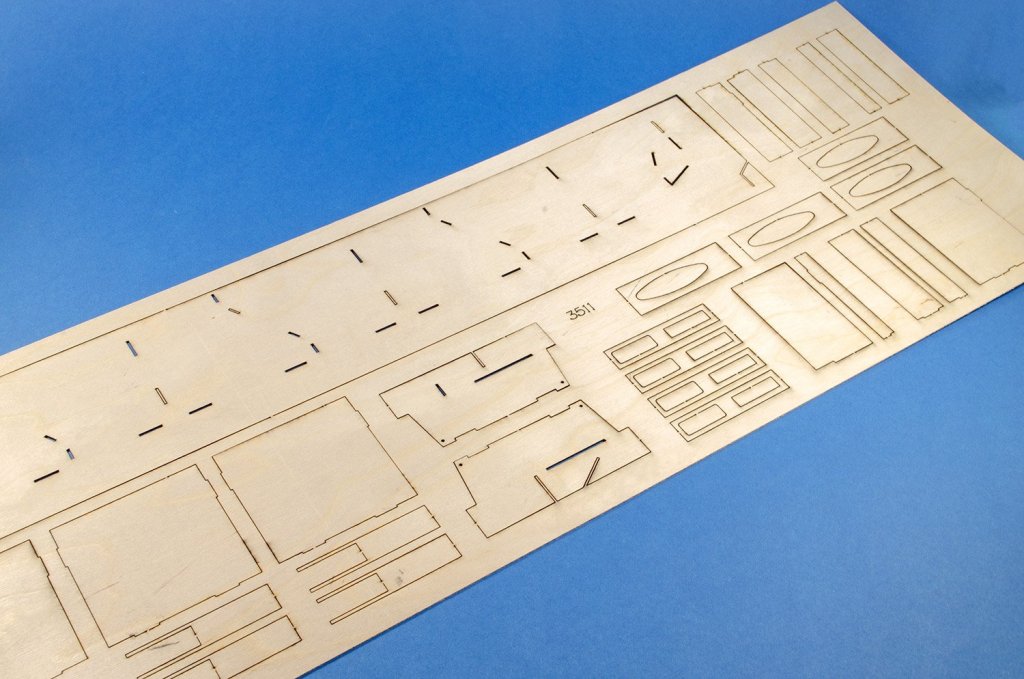
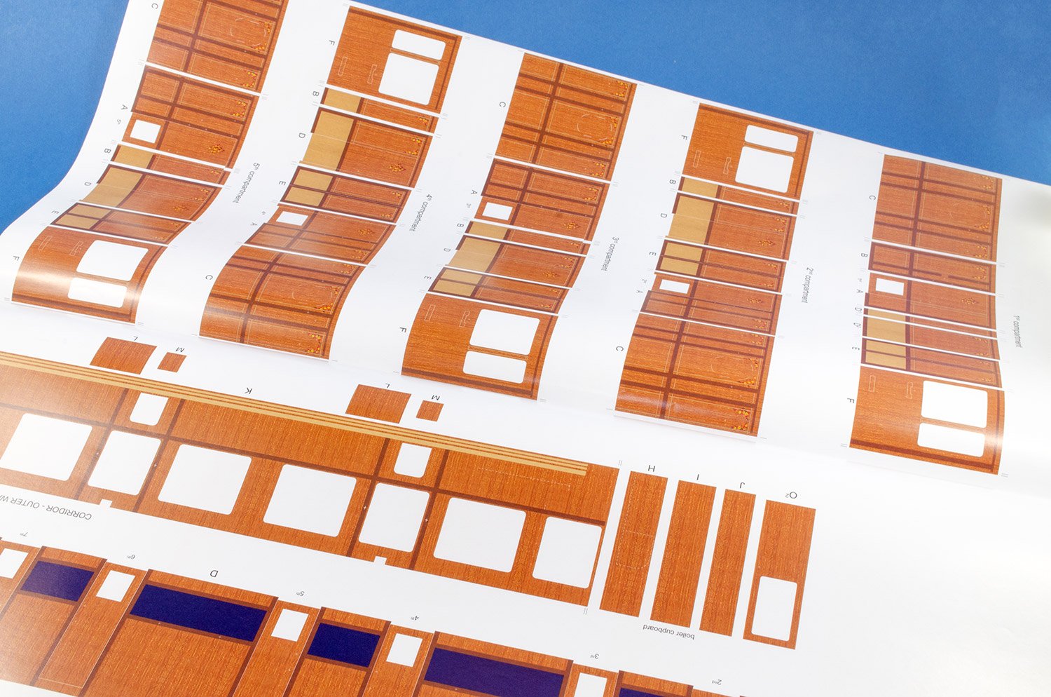
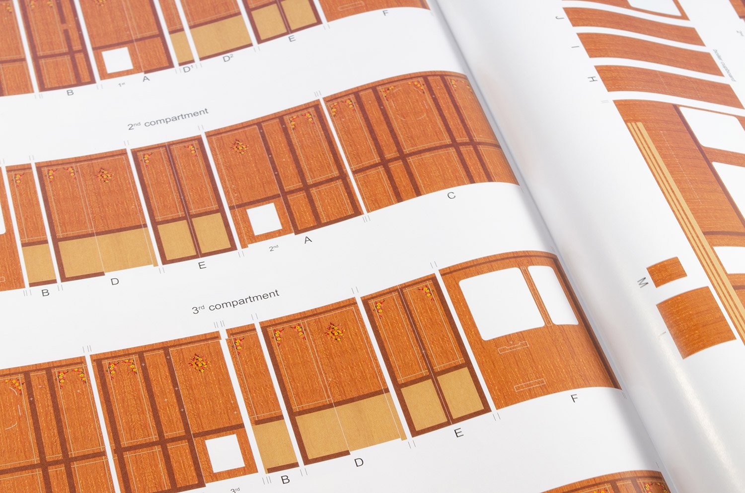
- 2 x gloss paper sheets with printed interior wood panelling and carpets. Also contains illustrations of exterior coach work for reference
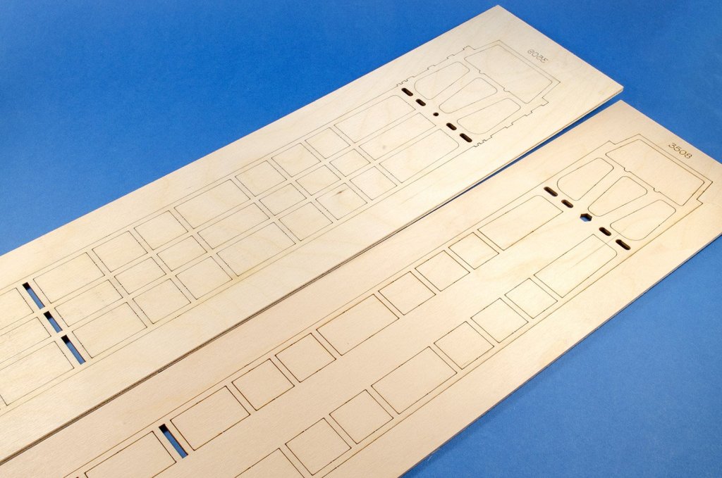
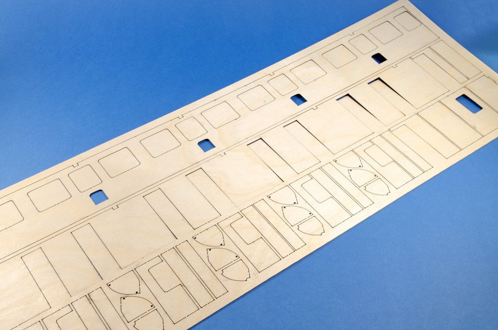
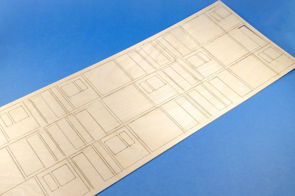
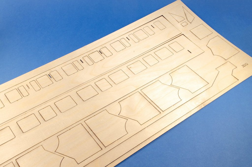
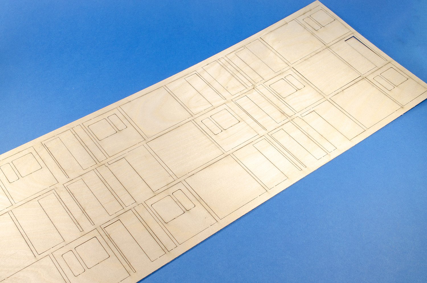
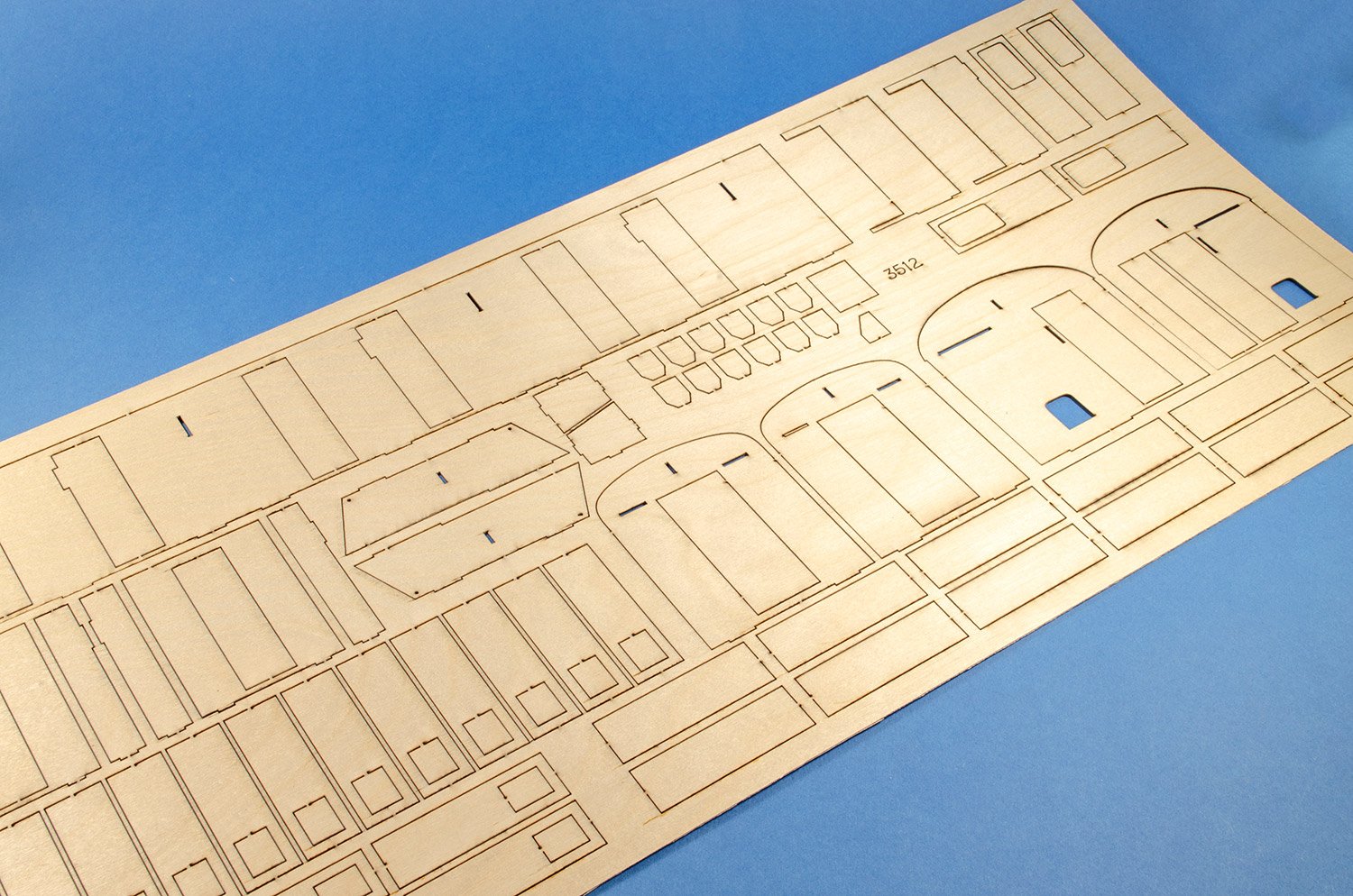
- 2 x laser-cut ply sheets for the carriage chassis
- 5 x laser-cut ply sheets for all side and internal walls/construction of the carriage.
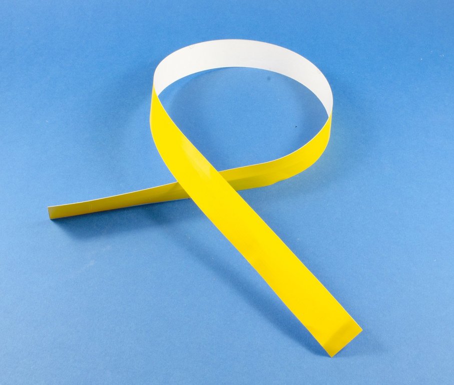
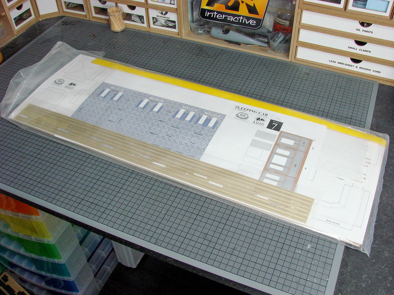
- 1 x tape of yellow self-adhesive trim of different widths
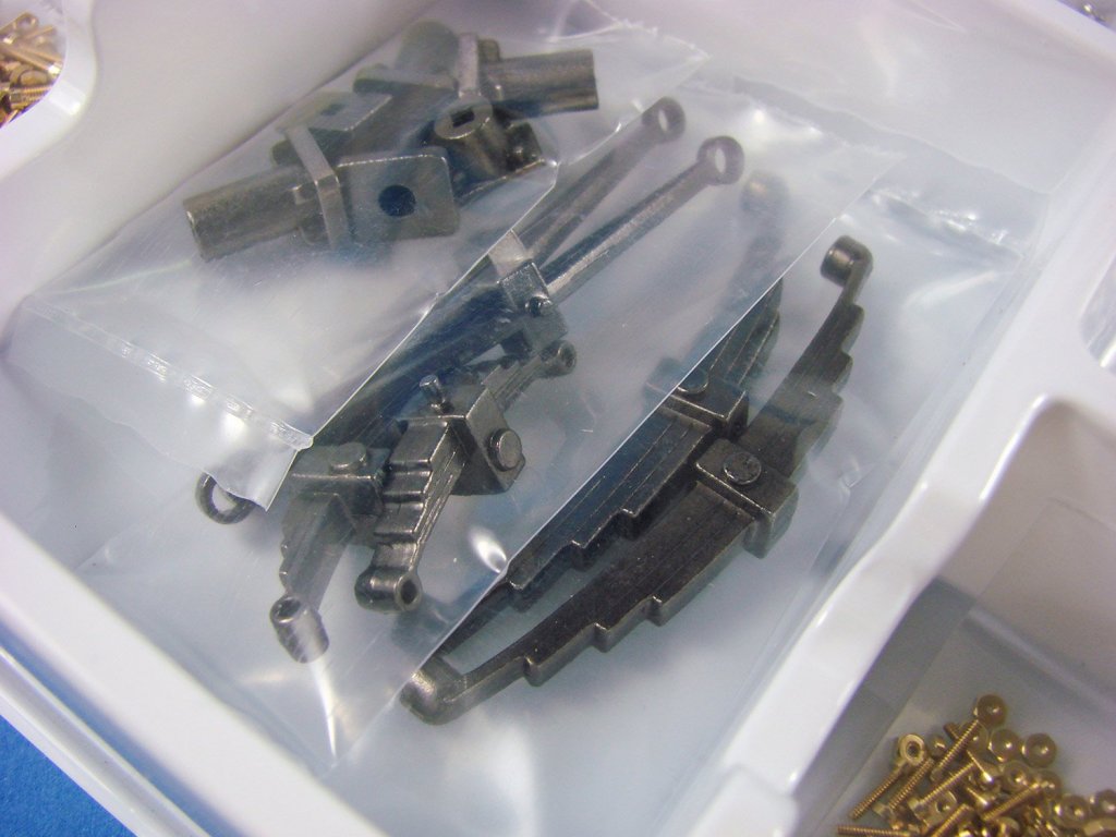
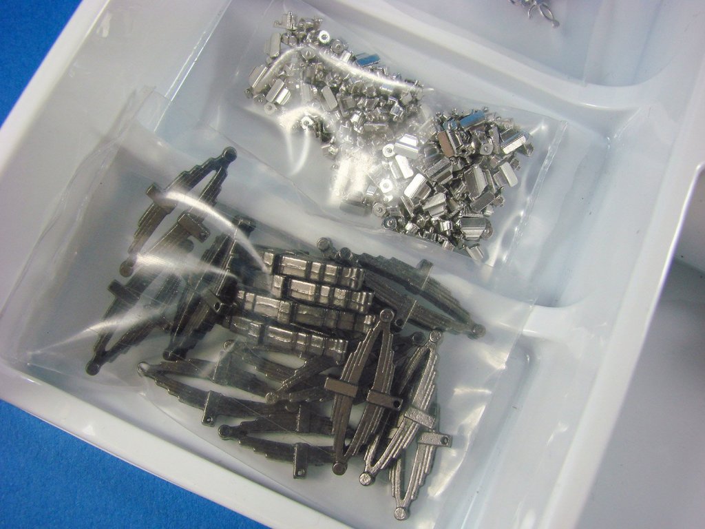
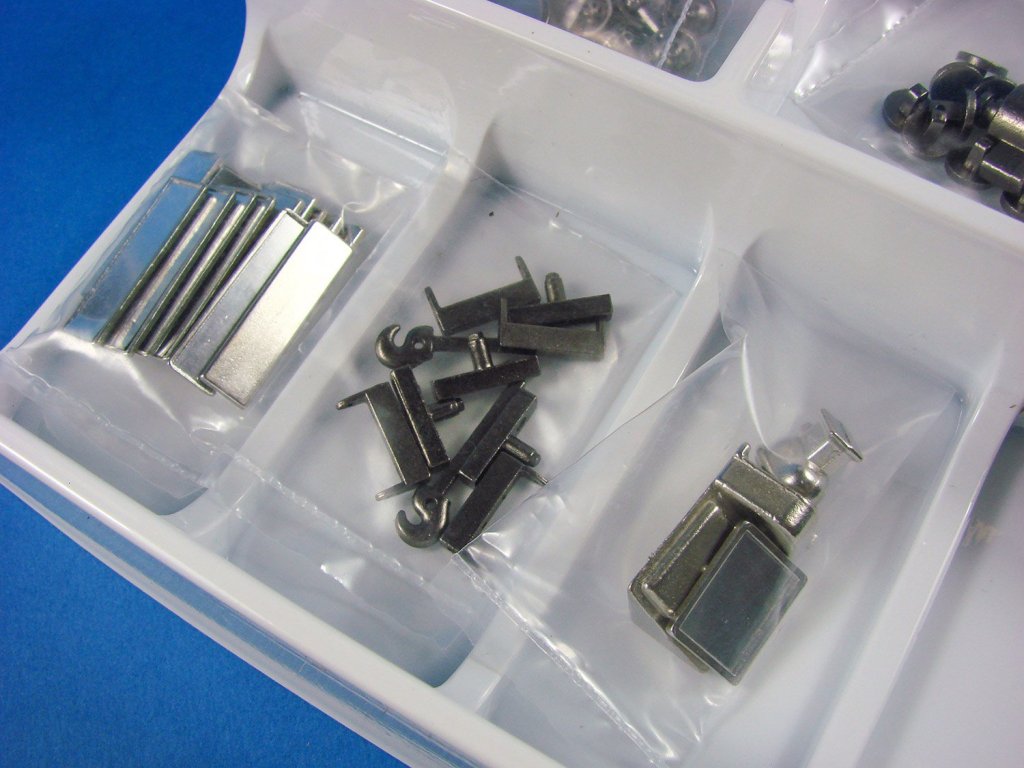
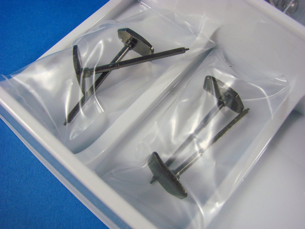
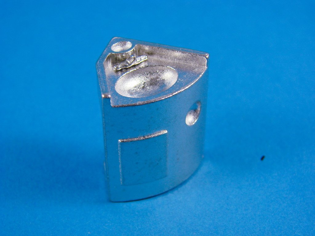
- 2 x white trays of cast and turned components, chain and wire. Parts include radiators, tissue dispensers, towel rails, wall mirrors, bottles and holders, soap racks, door handles, coat hooks, locks, eyelets, cabin lights, ventilation panels, electrical sockets, decorative cast exterior crest, spring-leaf shock absorbers, nuts, bolts, boiler, etc.
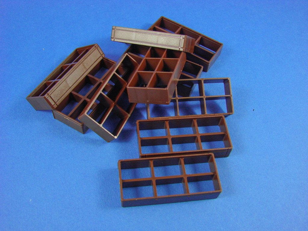
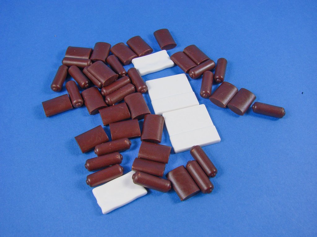
- 2 x boxes of components, contains parts such as sofa/bed carcasses and cushions, cores for the armrests and hanging headrests, rolling stock wheels and axles, sink units, stools, carriage entry tunnels, etc.
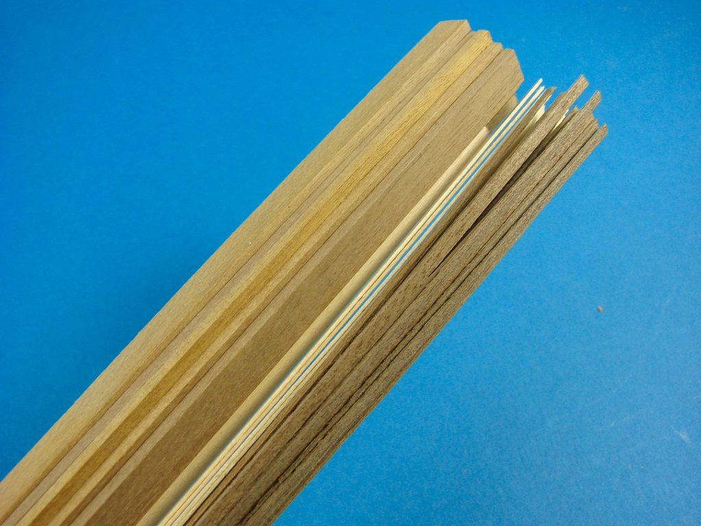
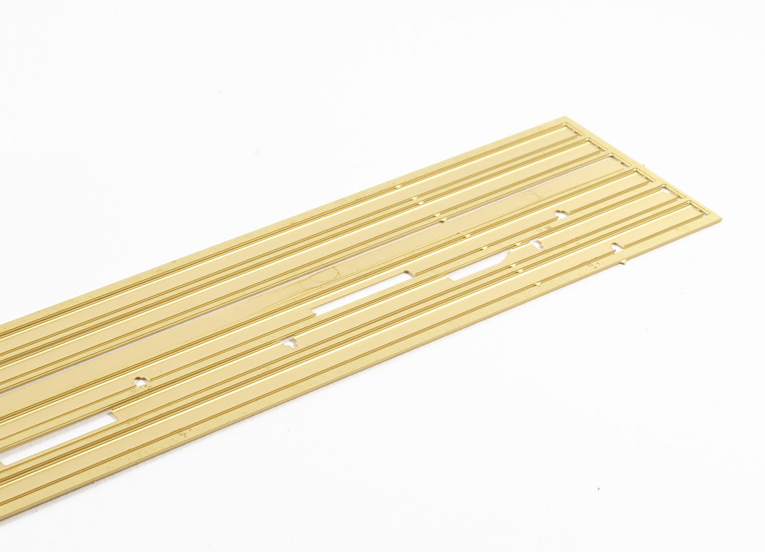
- 1 x pack of brass strut sections
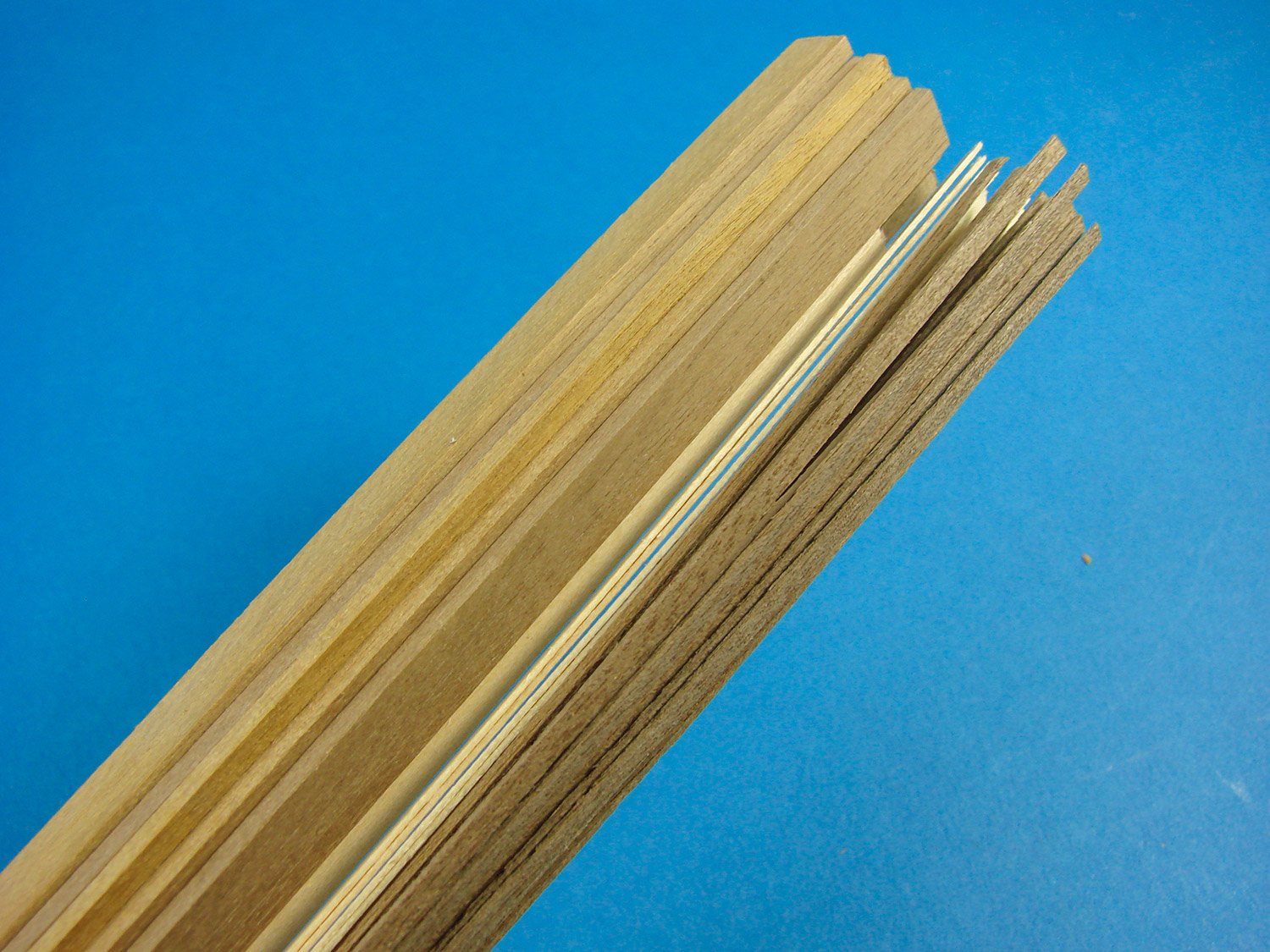
- Various timber lengths of varying size and type
- 3 x MDF track base sections and stirrups
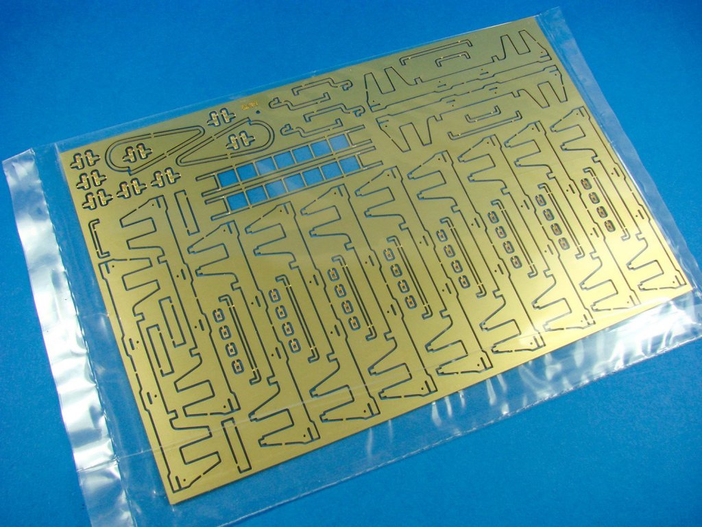
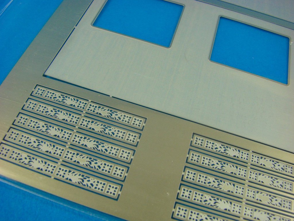
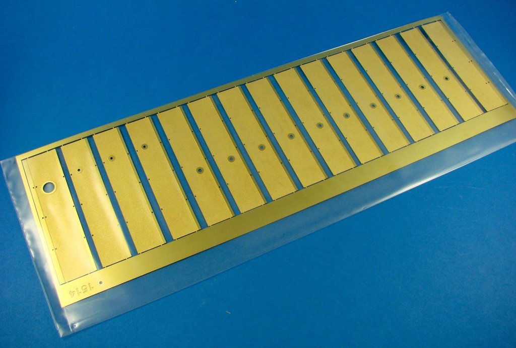
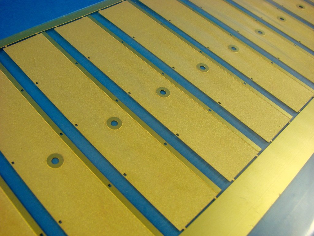
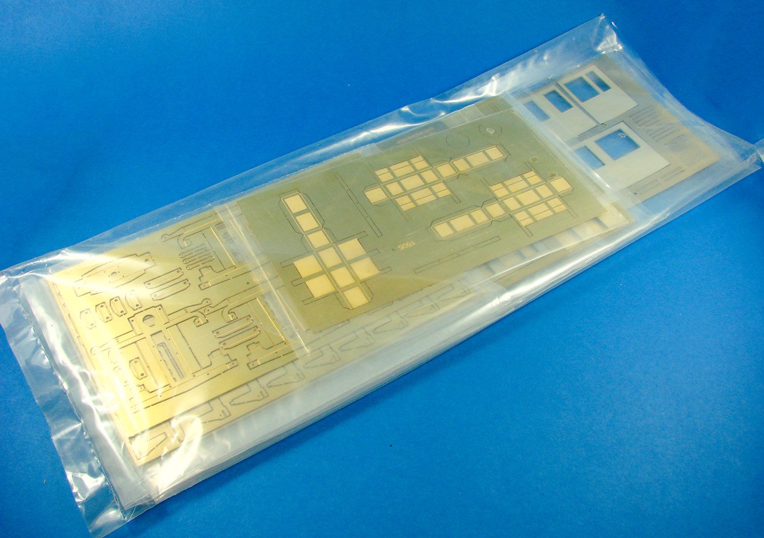
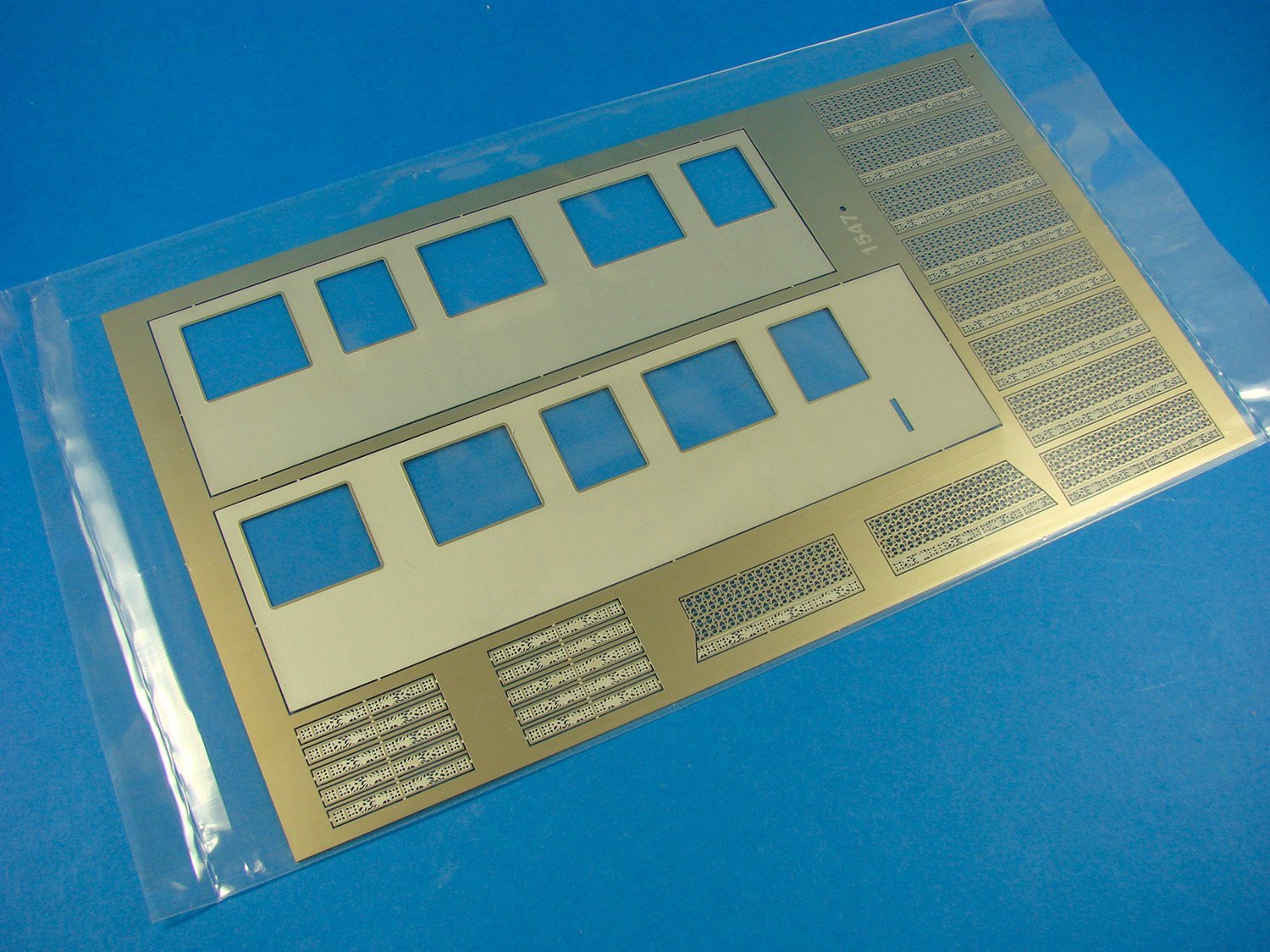
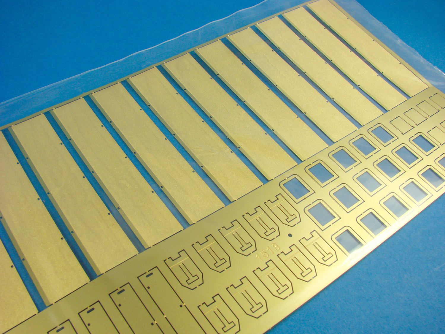
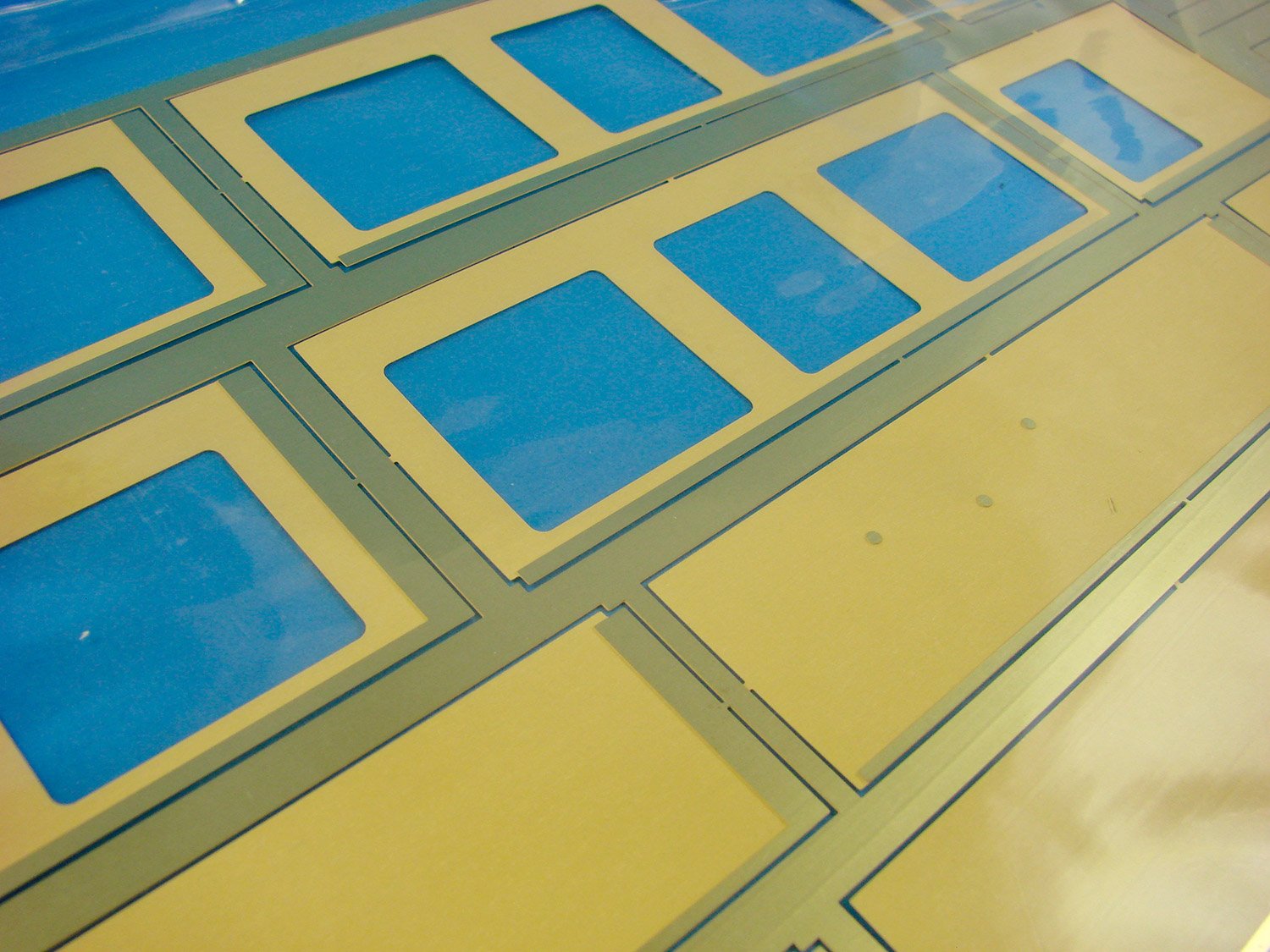
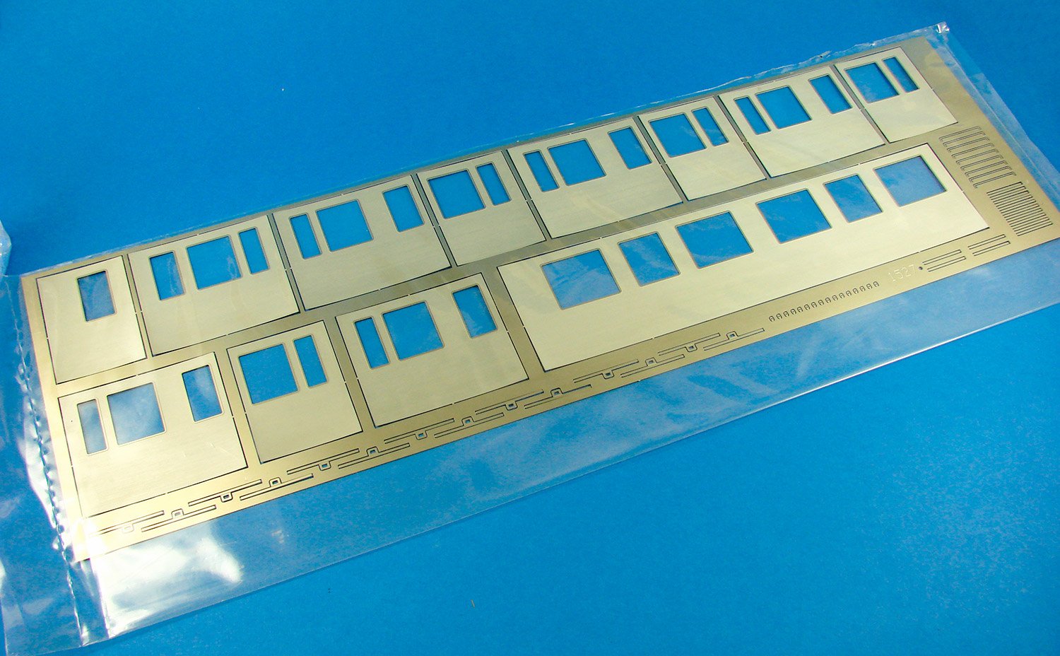
- 4 x sheets of photo-etch nickel-silver parts (internal main carriage wall panelling and hinges etc)
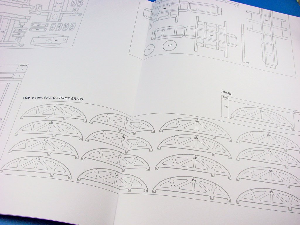
- 17 x sheets of photo etch brass parts (chassis, bogies, roof and roof sheathing, exyerior main carriage walls, etc.
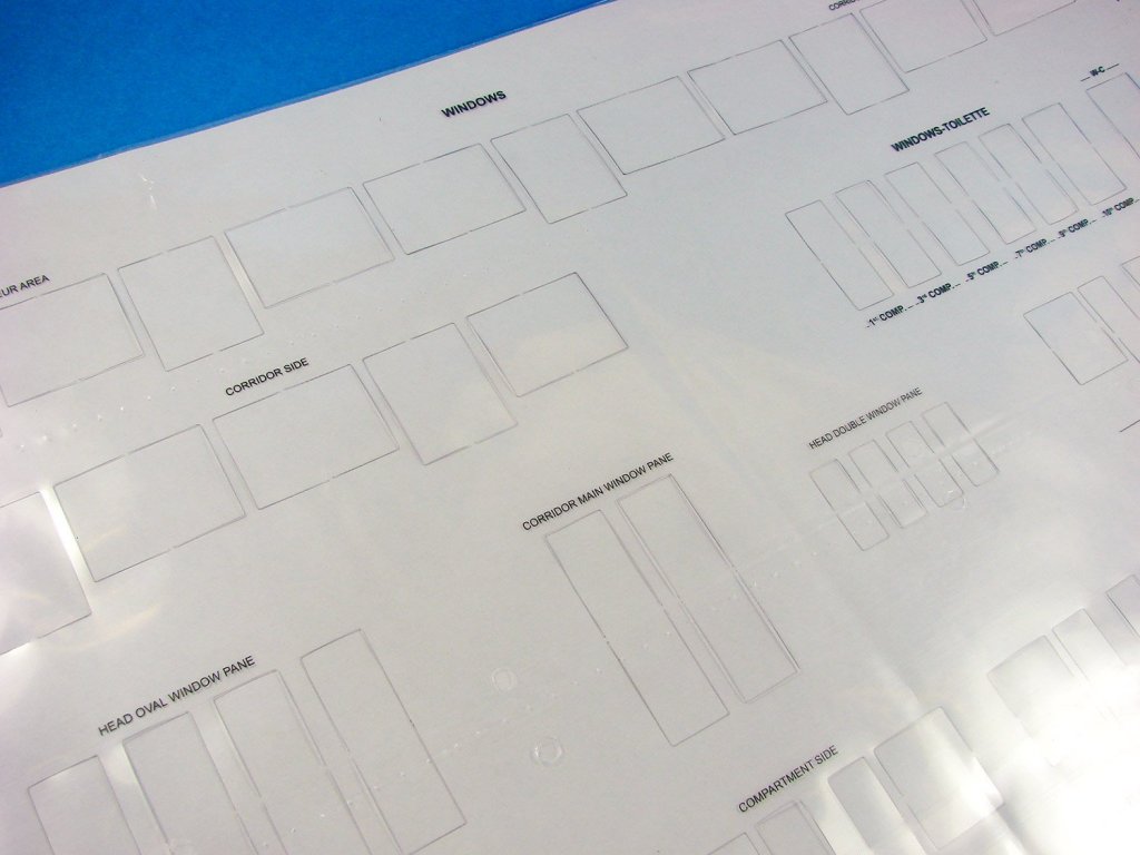
- 1 x sheet of pre-cut acetate for windows
- 6 x parts and plans sheets
-
2 x full-colour instruction books
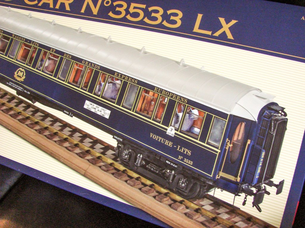
Now, a little about the model itself. Whilst the Orient Express is known for its amazingly high standards, these sleeping cars only had a single WC for the whole carriage. Amati has created an entire, accurate interior to this model kit, of which the toilet and small boiler closet are also included. To be able to see all of these details, the lid, constructed from photo-etch and rolled brass, is removeable.

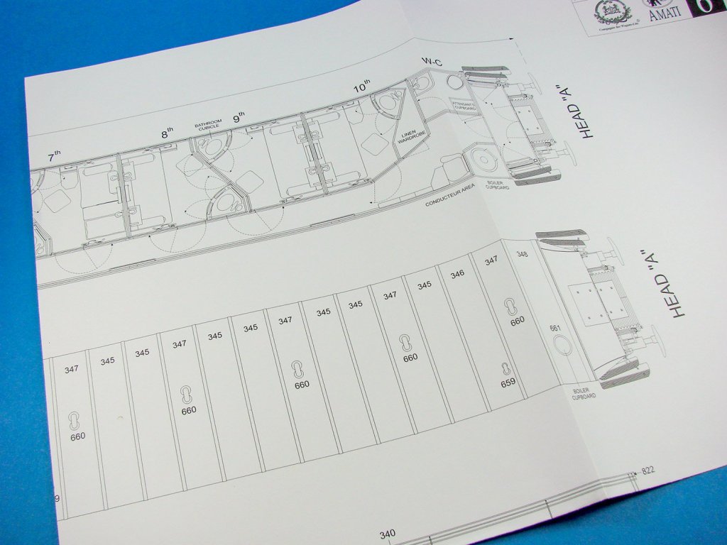
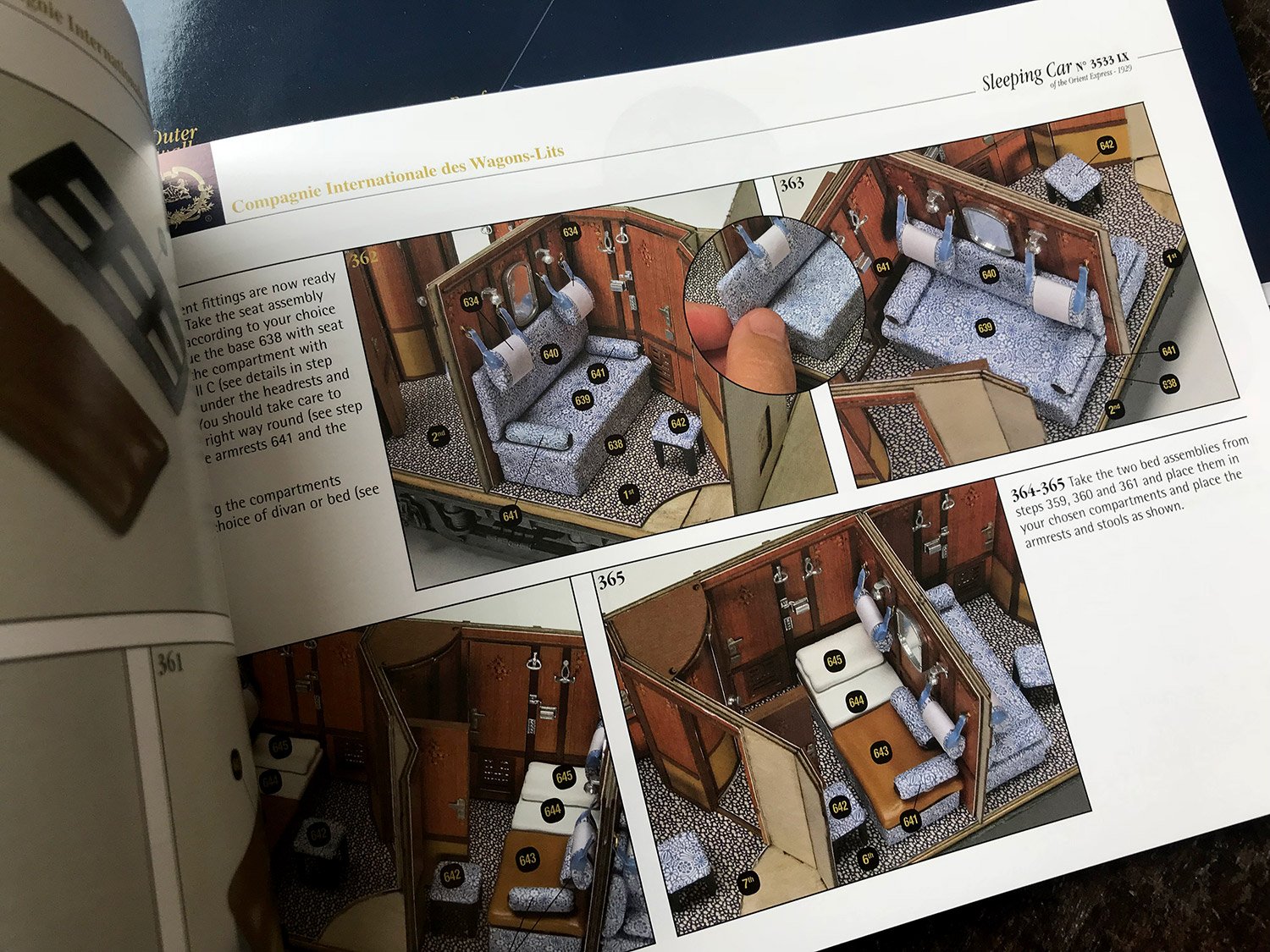
White card inserts for she shaped interior ceilings are included, and this would provide an amazing opportunity to add some soft lighting which would set off each of the cabins. Each of those cabins is intricately detailed, and whilst have no per-cabin toilet facilities, each cabin does have facilities for passenger ablutions. These come in a stylish curved-door unit which contains sink and other things which you’d expect to see in this area, all intricately reproduced in this kit. The walls of the cabins are wooden panelled, and all of the cabin creature comforts are present, including seats, cushions for arms and head etc, and ceiling racks for storing luggage. Remember, these cabins were pretty compact as passengers spent the day in other areas of the train too. An access corridor runs alongside the cabins, and of course, these are fitted out with radiators etc. In all, an impressive piece of rail history that Amati has gone to pains to recreate here.

The sleeping car is based on two lengths of laser-cut timber which sit atop each other to produce the main frame of the carriage. On the real thing, this would of course have been metal, so bear that in mind when building and ensure you seal any timber and rub down before filling, priming and painting in black. Added to the metal framework are lengths of heavy-gauge photo etch that create the authentic appearance of the carriage chassis. Other plates etc. are fitted out with miniature nuts and bolts. Brass section strips are also fitted to the entire length of the exterior frame, adding authenticity and some rigidity to the model. There is also a main bolt towards both front and rear of the carriage, onto which the moveable, wheeled bogies will mount. After all, your train won’t just roll in a straight line!


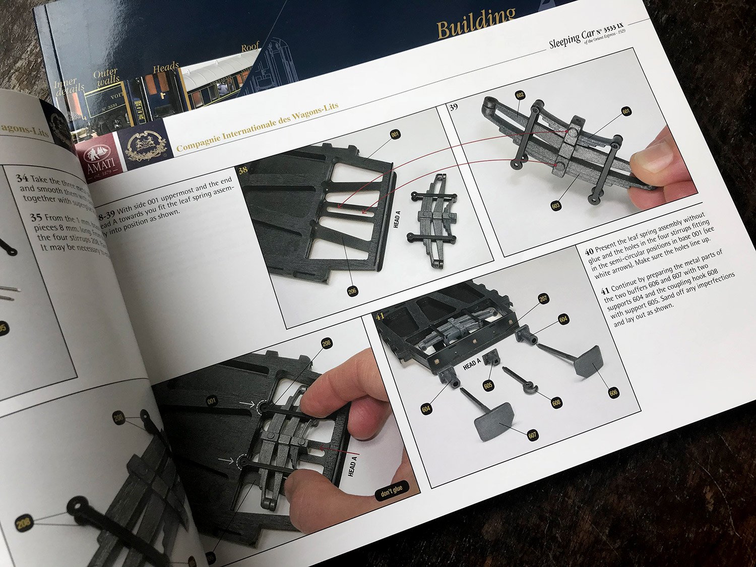
The underside of the sleeping car is incredibly complex with some superbly engineered and cast leaf-spring suspension for the buffers, couplings, photo-etch battery housings, compressed air tank, etc. Assembling the rolling stock/bogies themselves is broken down into over EIGHTY separate stages in around 20 pages of the first construction manual. Of course, all of the parts for this are manufactured from either photo-etch, cast or turned parts, and a photo-etch bending tool really should be mandatory if you wish to tackle this model. After all, if you are willing to shell out 890€ for a kit, then it’s foolhardy not to progress with the required tools.


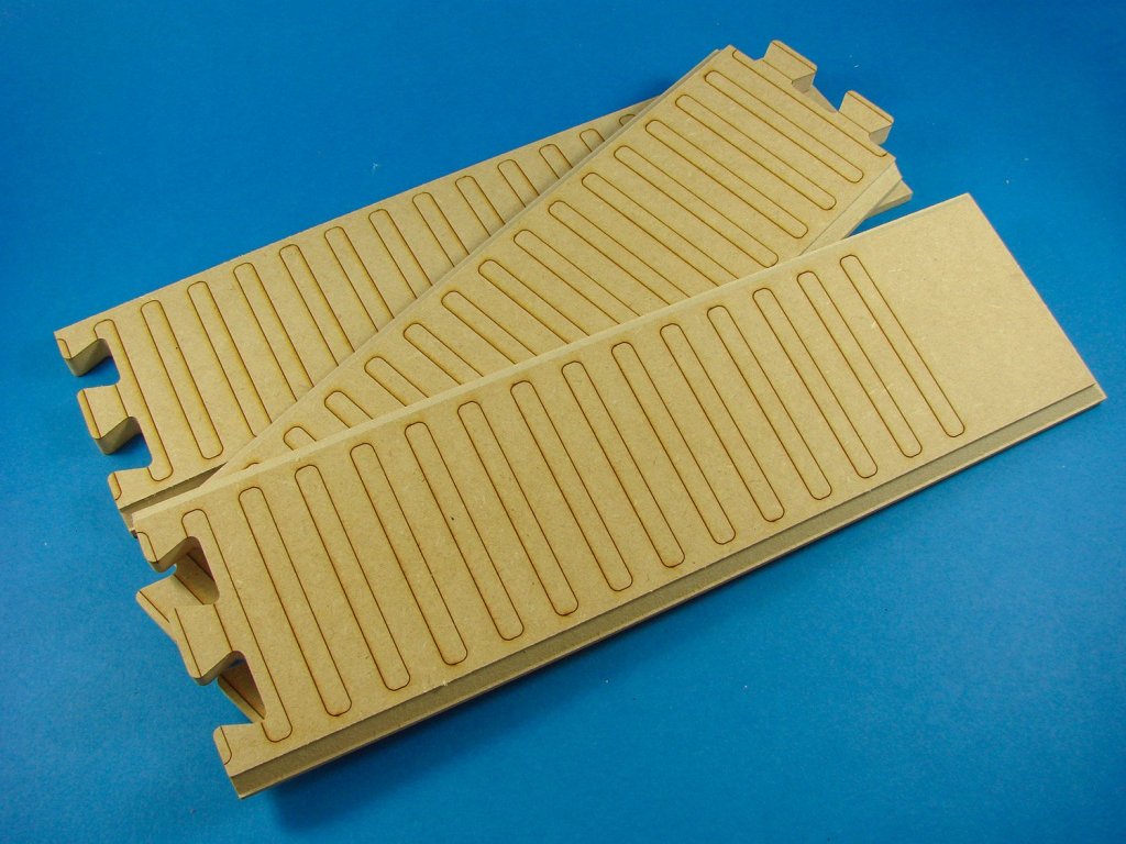
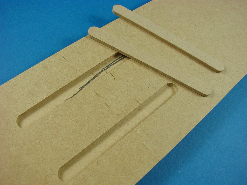
For the base, Amati has supplied three parts on dovetailed MDF which is profiled for display purposes. The positions of the sleepers is also engraved onto the top. I have to say that the fit of these is so precise that virtually no joint can be seen when they are put together. If you flip them over, you’ll note that there is a pencil mark to show you which part is the best match. Two MDF splints are then to be glued into the underside channels. Now, I don’t think that MDF is a strange material for the base, as you may wish to paint this, but one omission, for me, is any material that can be used to infill between the buffers, such as the gravel/stones. This would have been a nice addition so as to hide the MDF.

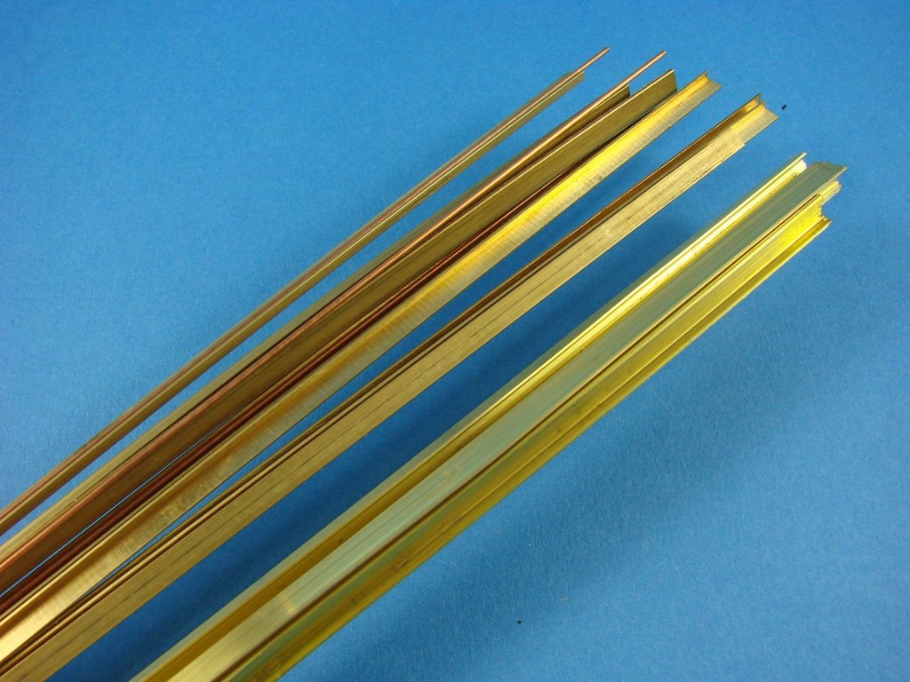
The tracks themselves are supplied as brass sections which need to be cut to length. As per the real thing, the tracks are attached to the sleepers by the correct hardware. I would use an assembled wheel/axle section to properly ensure that the tracks are equidistant at both ends, as well as traditional measuring. I would also look at either painting the tracks in an iron colour, or if you can immerse them in a shallow bath of burnishing fluid, then that would also fit the mark.

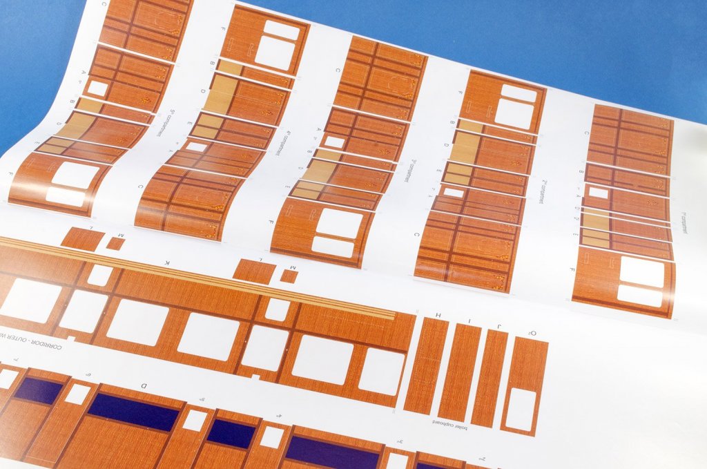

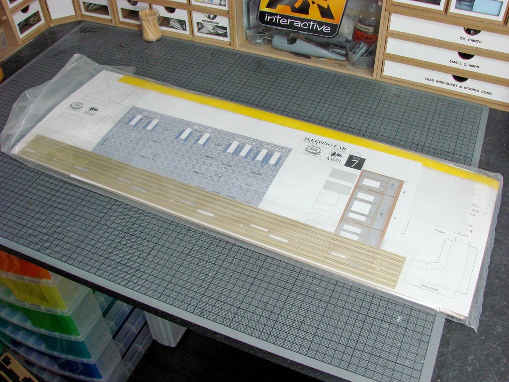
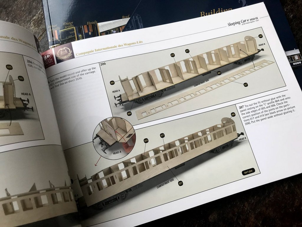
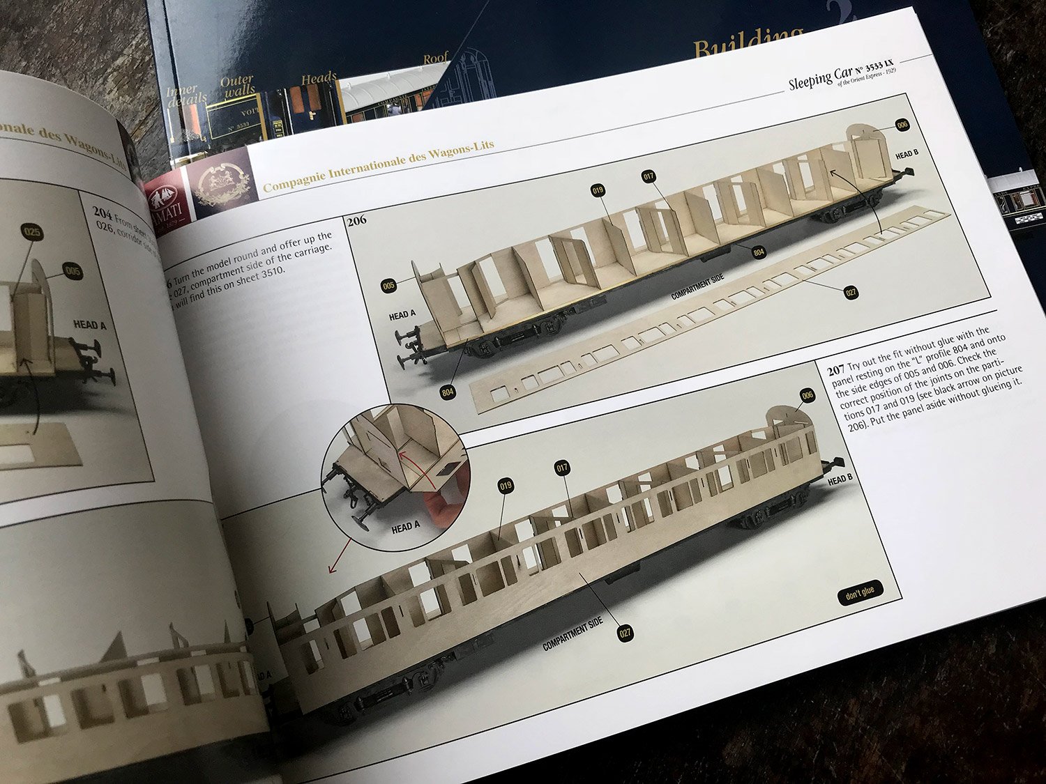
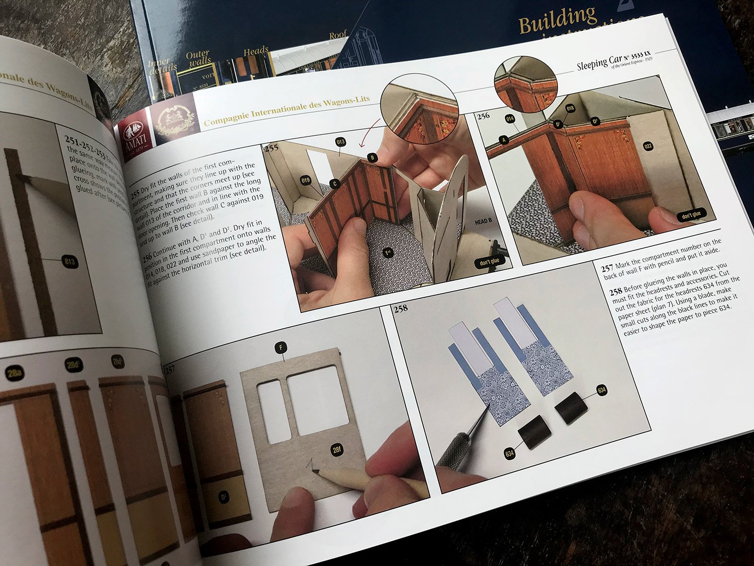
With the base of the model now built, the time has come to assemble the carriage itself. This initially starts with the Head A and Head B bulkheads, followed by the fitting of the interior corridor wall. Onto this are fitted the interior compartment walls, creating the cabins. Please note that a lot of paper cutting will be required as the internal walls in their antique finishes, are printed matter and will need to be fixed to the pre-sealed internal plywood walls. This will also be enhanced with actual timber framing too. The printing of the wooden walls is very, very nice and should look as good as trying to emulate this using precious timbers.
Besides, this approach means we all stand a level chance of success. Actual timber will be used to line the panels, adding to the realism. The carpets are also to be cut from paper. You will need to pick up some paper-crafting skills too as the numerous head rest and arm rest cores, sofa/bed chassis and stools, will need to be wrapped in the same matching paper and neatly fashioned around corners. There are some good techniques to be found online, such as dampening the paper to make it easier to mould around corners etc.


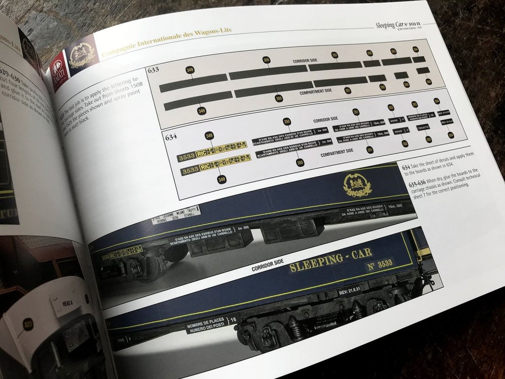
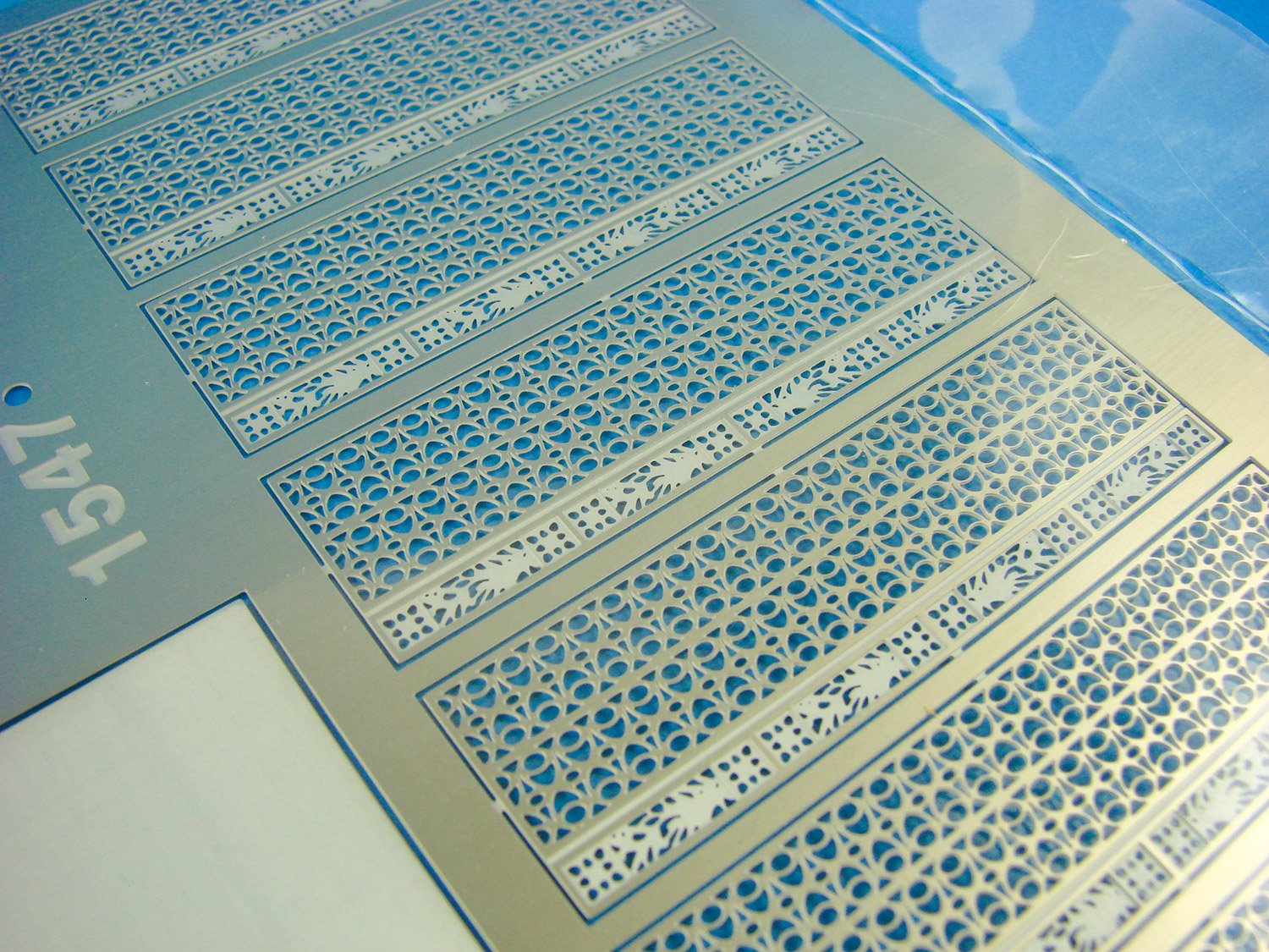
Each cabin will also have its own wash locker, and these are constructed separately and then installed. As well as having all the mod-cons, for the 1920s, the doors on these will actually hinge open and closed. You won’t have this option for the cabin doors though, but these can be posed in any position using the nickel-silver etched parts. The main carriage exterior walls are sheathed in photo-etch brass which will be painted, and the trim/decals added. Internally, those same walls are plated with the nickel-silver panels. I don’t know the reasons for change in material from brass, but the panels are superbly produced. Remember, there’s no actual silver in those parts. Instead, it’s an alloy of zinc, copper and nickel.


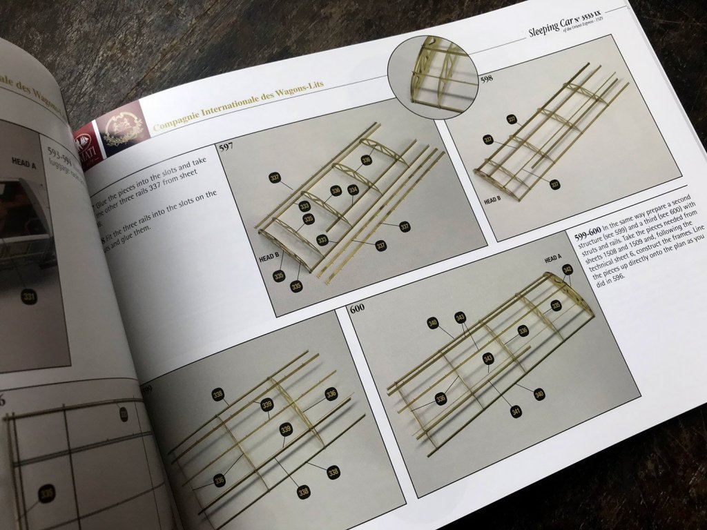
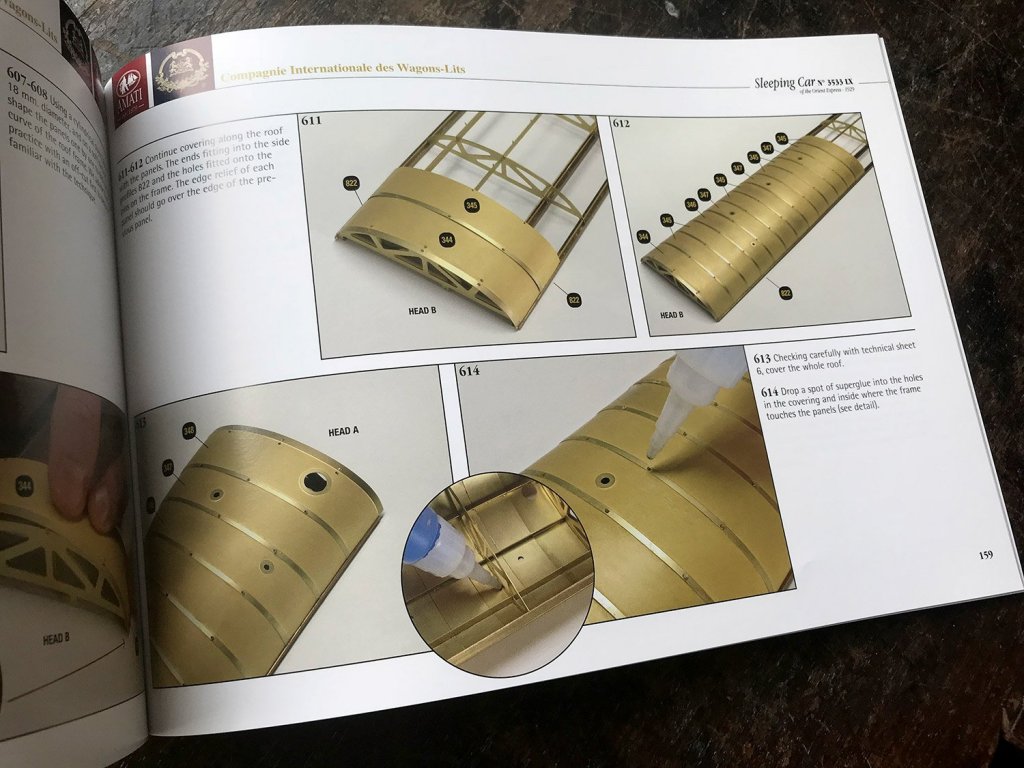
To construct the carriage’s roof, a series of photo-etch frames are interlinked with longerons that have raised pips. Once the basic frame is assembled, a series of individual brass panels are then rolled into shape and the holes in these used to lock over the raised pips of the longerons. Whilst you can use CA generally, I would suggest that the pip areas are soldered and filled before then being filed back flush to the roof. The roof is then painted white. Internally, the card mouldings are then shaped and sealed/sprayed white before decorative wooden edging is applied.
Instruction manuals
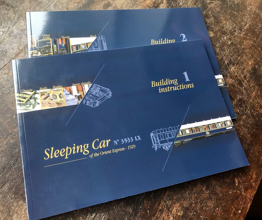
Two full-colour instruction manuals are included, showing the various stages using photographic images and clear text in English, with Italian also. Each step is very easy to understand, in the way that magazine part-works are designed to be straightforward. There’s nothing here that should catch any modeller out, meaning that the only thing you need to have some experience with is photo-etch. Each manual is landscape in format, and perfect-bound, as a novel would be etc. Paint references are used where necessary and supplied in FS codes.


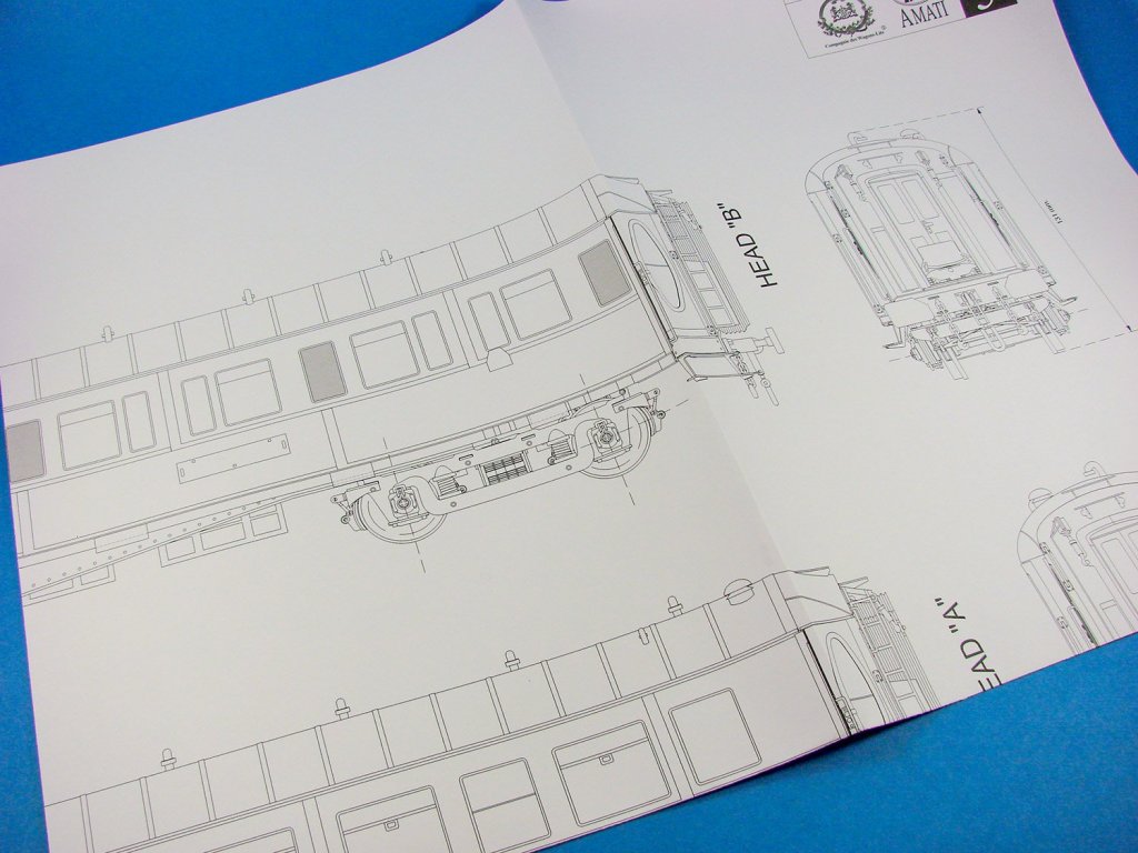
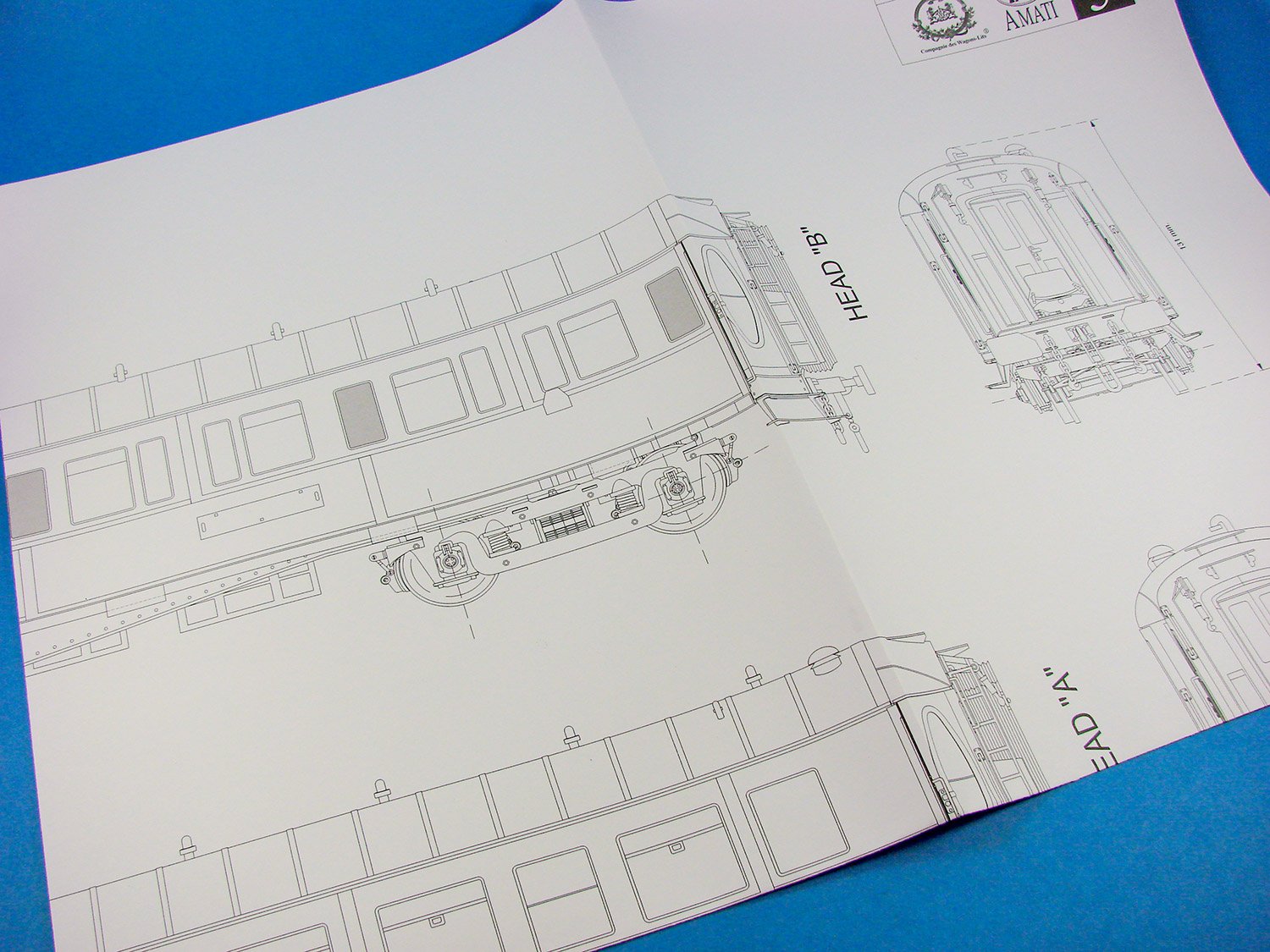
Plans
A number of these sheets are simply for helping the user to identify the various PE parts and wood parts, with a couple of others showing the rail carriage in various plan formats. All line drawings are clear to understand shouldn’t provide the modeller with any issue.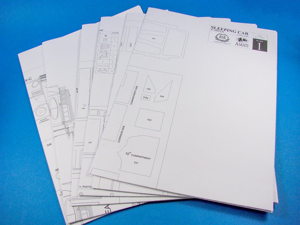
Decals
A single sheet of waterslide decals is included for the exterior livery signwriting etc. Print quality looks excellent. It could be worthwhile trimming any of the clear carrier film as close to the actual decal as required.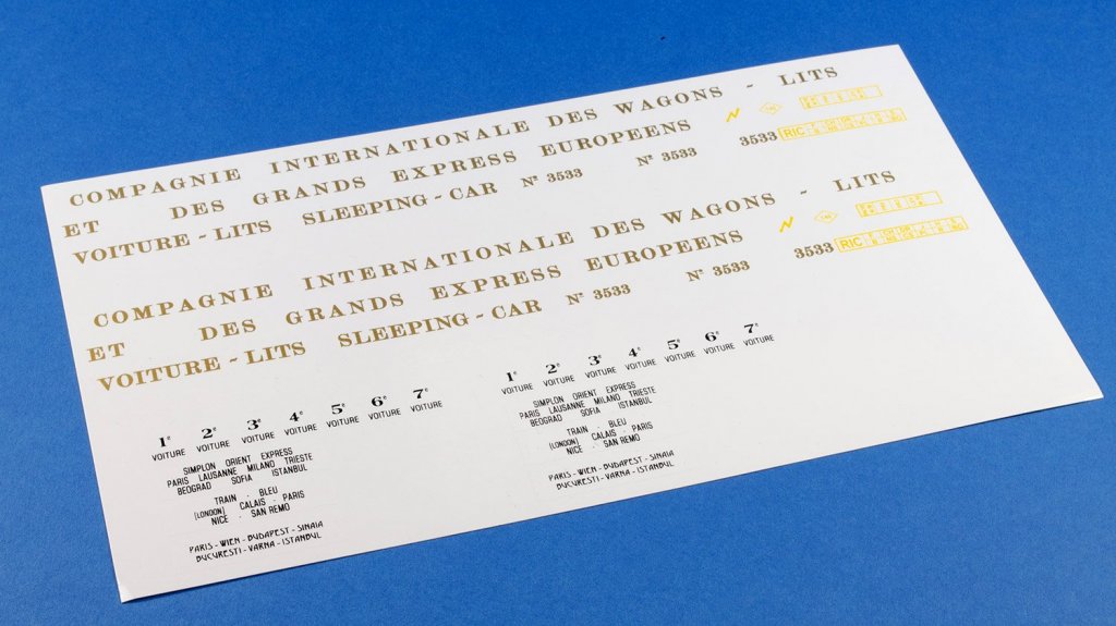
Conclusion
This isn’t a cheap kit by any stretch of the imagination, but it is an epic one in every sense. The Orient Express kit is a sort of crossover between vehicle and doll’s house building, with some beautiful period features in the mix. It’s certainly a project that will command a lot of time from you in order to achieve the very best outcome. You really do have to be reasonably adept with photo-etch metal in bending, curving and folding, and although you don’t strictly need to, some elements would be better soldered than glued. A lot of attention to detail has been made here, from the kit detail itself, down to little things like the cut-out paper décor not lying across folds in the sheet paper. The instruction manuals are also a work of art and should be a cinch to follow. Projects like this are usually once in a lifetime, so if you fancy doing something pretty unusual, then this has certainly got to be a major contender. These kits are hot off the press, only having being released within the last 2 weeks, so get them whilst their fresh!My sincere thanks to Amati for sending this kit out for review on Model Ship World. To purchase, check your favourite Amati shop or online retailer. Tell them you saw the review here on MSW.

-
Impressive!
Which ship is this?
- BenD and MarisStella.hr
-
2
-
Struggling with pre-formed ply planking at moment, so put on hiatus.
New build project starting soon.
- Jobbie, Canute and Old Collingwood
-
3
-
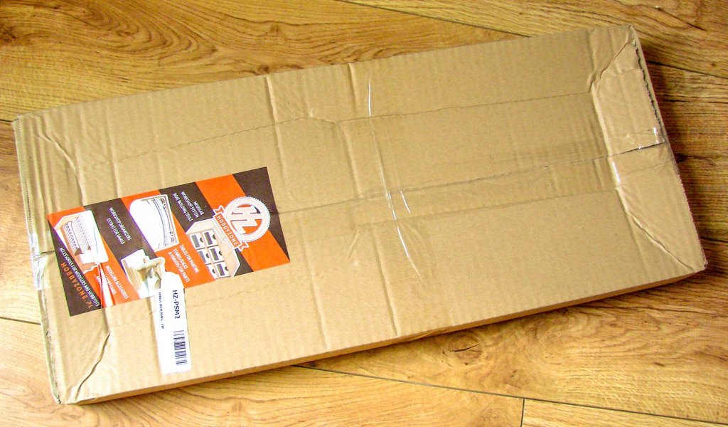
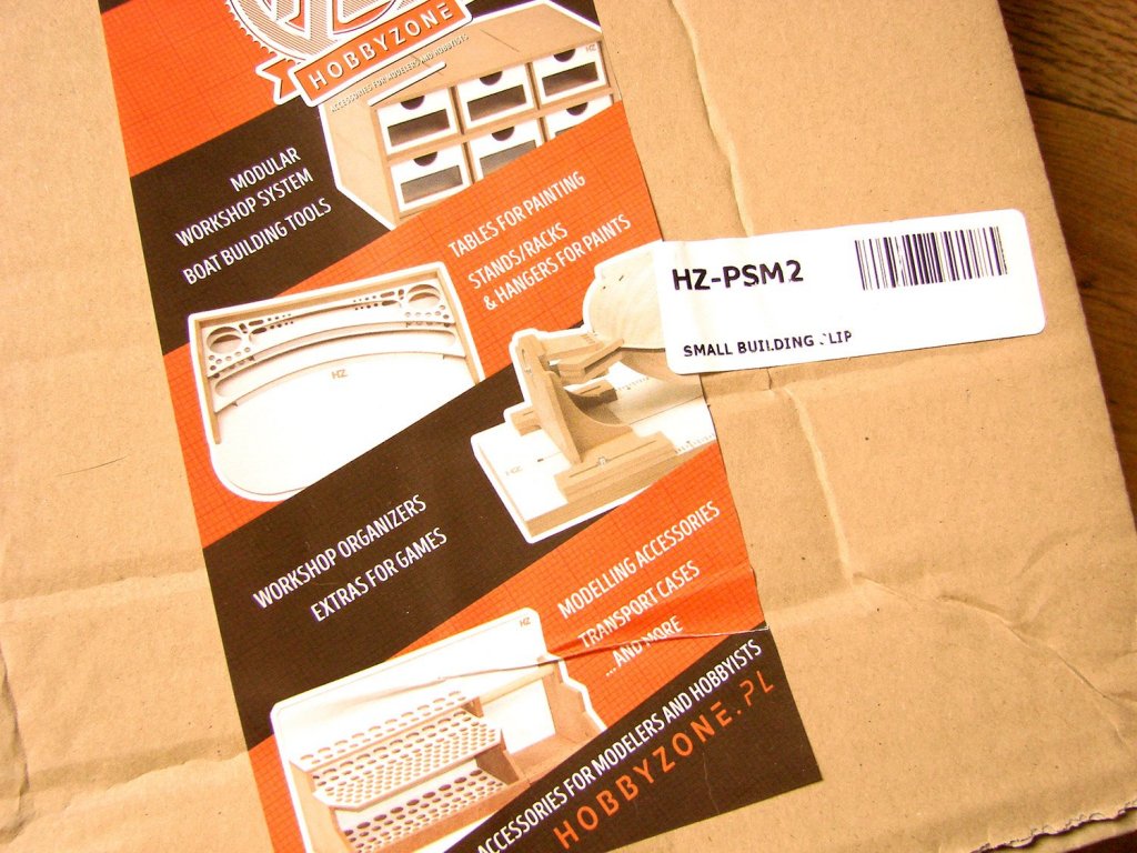
Small Building Slip
Hobbyzone
Catalogue # HZ-PSM2
Available from Hobbyzone for £25.79 (as of 11th July 2018)
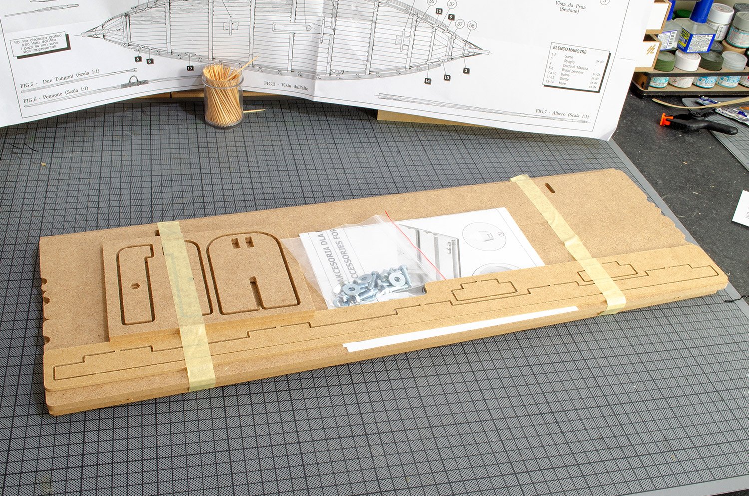
My original intention for this review was to do something in the style of the waterline marking tool, but as I've already been asked to create a building guide for the Professional Building Slip which I will publish next week, I thought I'd put the style to practice for this article so that Hobbyzone has something that they can use to refer their customers to. This will be a comprehensive build review...almost like a manual for assembling this product. The product itself is packaged into a cardboard box and the materials within are wrapped in a LOT of bubblewrap to protect further. Furthermore, the contents within are also bound by masking tape to prevent them joggling around in the box.
All parts within are made from MDF which has been routed out, leaving only shall tags that can be cut through with nothing more than a craft knife. A number of parts have a white finish to one side. A small bag of hardware is also included. All you will need to assemble this is some wood glue, craft knife, and clamps.

Onwards with the build....
1. First of all, remove the MDF tags that held the parts into position on the boards. A craft knife is perfect for this. You won't need files etc.
2. Take two of the bolts and fit them in the main board. No glue is needed. Flip the board over and now glue the forward strip with the white edge, into the tabs at the front of the slip. Do the same with the small edge pieces. You may consider clamping these until set. Now, tale the narrow MDF slat which has the notches towards one end and glue this right up to the small edge pieces you just fitted. Those notches MUST line up with the ones on the baseboard. Again, clamp this until fully cured.
3. Take the remaining two strips and glue one on top of the other so that the notches line up. The parts will be stepped. Use a pencil to first mark the position and to make placement of glue more precise. When glued, clamp until set.

4. Take the parts shown here and glue them together. Please note the location of the hex indent. Clamp until set.
5. Fit the bolt, washer and nut into position.
6. Take the parts shown here and assemble in this orientation. Note that these are made as pairs, with the base fitting on one pair being opposite to the other pair.
7. Sit the moveable portion of the slip onto the baseboard and use the washers and wing nuts to secure. This portion of course is adjustable to the width of the keel. The other smaller parts, including the end stops and bulkhead clamps are fitted by simply pushing and twisting them onto the stepped edges of the keep clamp. You can use any of the features seen here in any way you like in order to assure yourself that everything is in alignment. A small tray at the front of the slip can be used for the unused parts, or modelling tools.


Enjoy the build and your next project you build with it!
In all, a nice and easy slip to build and one with quite a lot of flexibility when it comes to the shape of the vessels that can be constructed on it. The slip is designed for models with a keel length of 600mm, but 800mm can be built within it too. Maximum keel width is 5mm, according to Hobbyzone, but I'm sure you could squeeze another millimetre out of it. To give you an idea about keel thickness, the 1/72 HMS Vanguard from Amati/Victory Models has a 5mm thick keel, and that model is designed for a bigger slip than this! SO, in short, you should find this perfectly capable of handling just about every project up to a maximum of 800mm keel length.
My sincere thanks to Hobbyzone for sending this out for review here on MSW. To purchase directly, click the link at the top of the article, or head over to your local Hobbyzone stockist.

- Jasseji, Ryland Craze, thibaultron and 5 others
-
8
-
Any progress here? Lovely looking build so far.
- Old Collingwood and EJ_L
-
2
-
Hi all,
All members of MSW are entitled to publish their kit reviews in this area. It isn't just a privilege for staff members. We want a collective voice as to the evaluation of kits, both old and new. However, there are some very simple guidelines that really must be adhered to in order for this section to work as designed. Also, all kits under review must be un-started. This is the only balanced way to get an overall initial feel for the kit.
Kit reviews must:
- Give an initial assessment of the overall package with regards to standard and presentation.
- All materials must be assessed for quality, including ply and other timbers including strip and dowel, fittings, photo-etch, rigging blocks and cord, sail materials, decals (where supplied), cast materials including cannon and culverins etc,
- Kit design approach.
- An overall, personal assessment of the model construction and other interesting and pertinent things you note as you look through the plans, instructions and other drawing materials.
- Your review must contain clear photographs. Nothing hazy or fuzzy etc.
Please do not use this area for starting new topics asking questions about models that aren't under review. Where you do wish to ask a question about a review, then post it as a reply to the review topic, and hopefully those questions can be answered.
This area isn't a general model kit discussion place. Please respect the intention of this area and keep other discussion within the other relevant forum areas.
Thanks,
Jim
- Ryland Craze, Canute, mtaylor and 3 others
-
6


Hello from Spain
in New member Introductions
Posted
Nice to have you here Victor. I hope you get the answers you need.