
.JPG.ca33079f5815b861e67b9c2cccd37982.JPG)

Blue Ensign
-
Posts
4,520 -
Joined
-
Last visited
Content Type
Profiles
Forums
Gallery
Events
Posts posted by Blue Ensign
-
-
Thanks Daniel, I obviously didn’t have my old brain in gear when I followed Chuck’s lead which is directed towards a fully planked hull, where such details don’t matter.
What I don’t know is how permanent these platforms were. Could they be removeable for access to the space below, merely slotting into place between the frames, even fitted in two halves?
Either way, I will replace the random supporting boards with specific support beams which match the nail runs and hopefully look aesthetically better from beneath.
Regards,
B.E.
- Thukydides and CiscoH
-
 2
2
-
Post 24
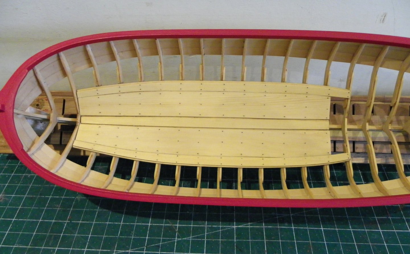
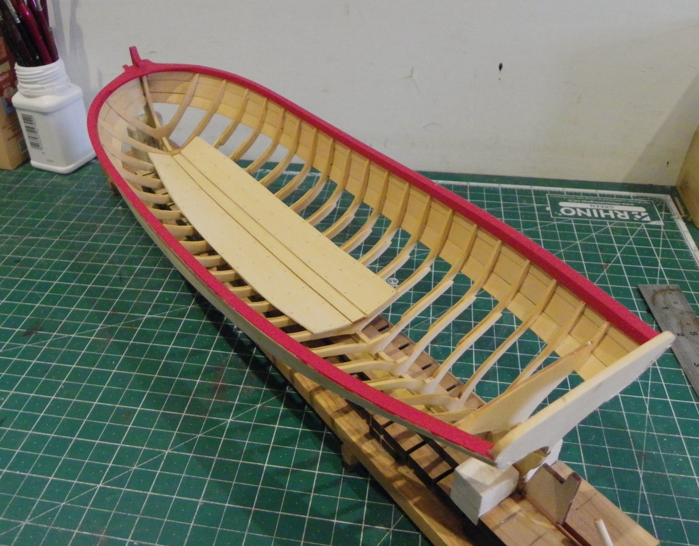
Platforms.
After a break in Devonshire and taking advantage of recent fine warm weather to work in the garden, I return to the Longboat build.
Has it really been a month, better crack on.
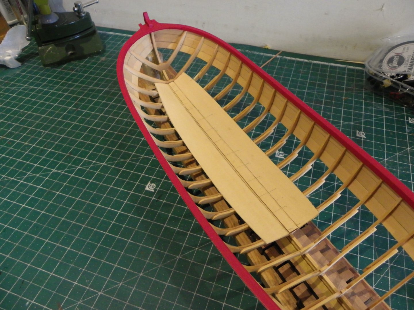
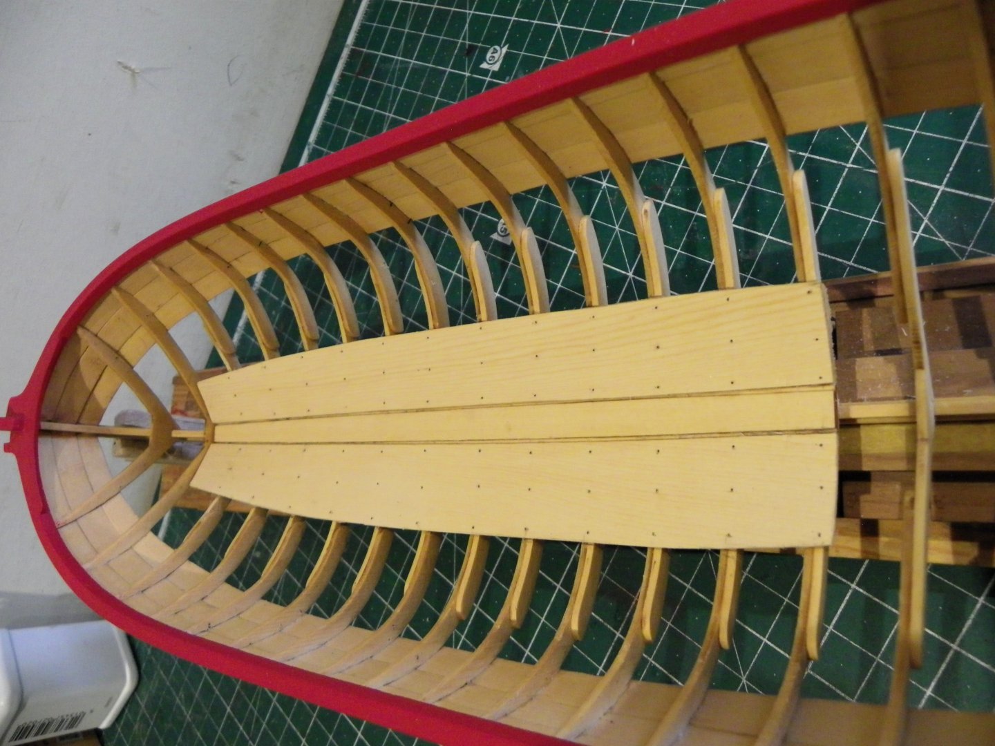
Fore and aft platforms are now to be fitted.
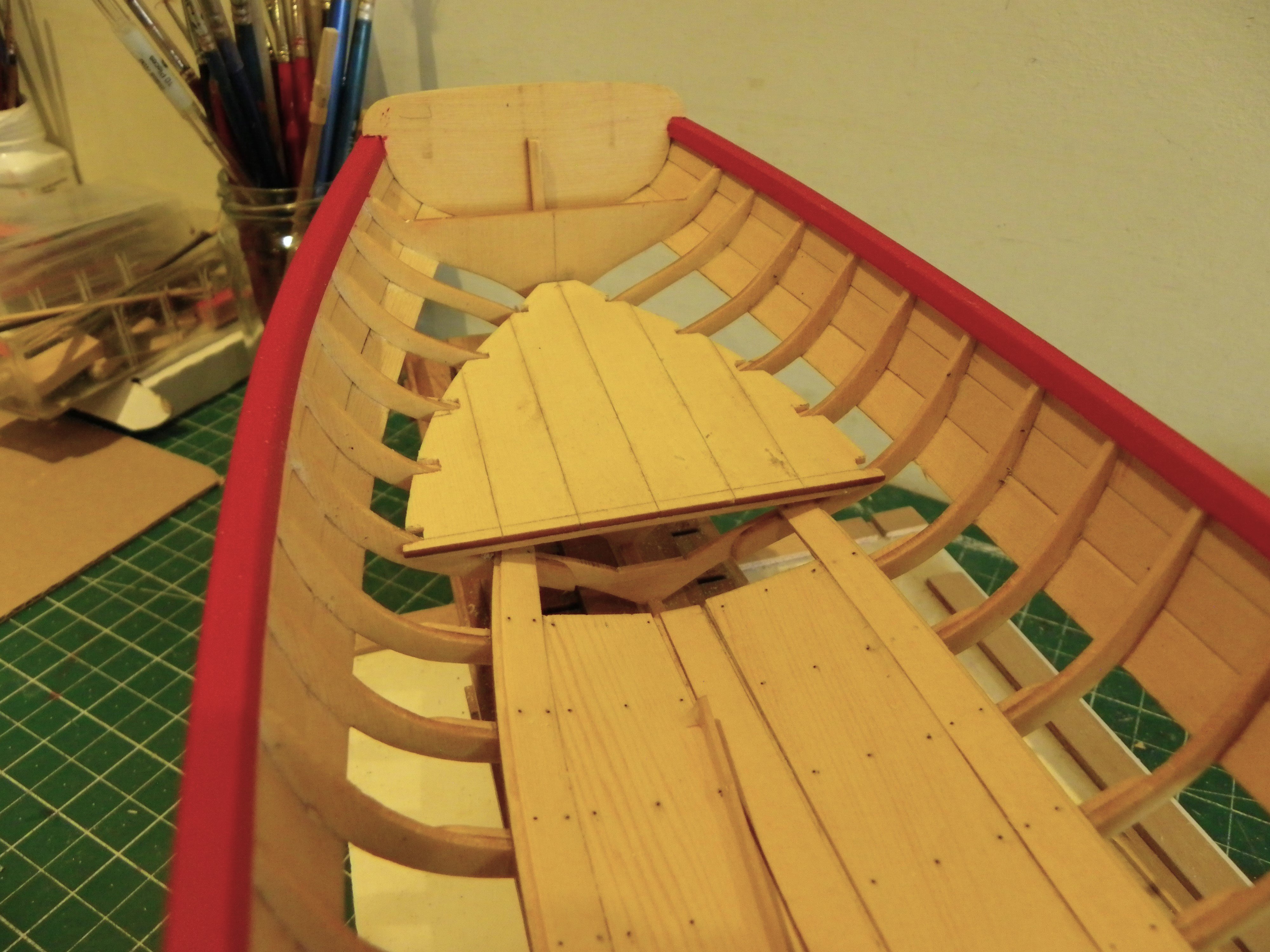
Aft Platform
Initial assembly is quite straightforward, it’s the notching to fit over the frames that is the tricky part.
0086
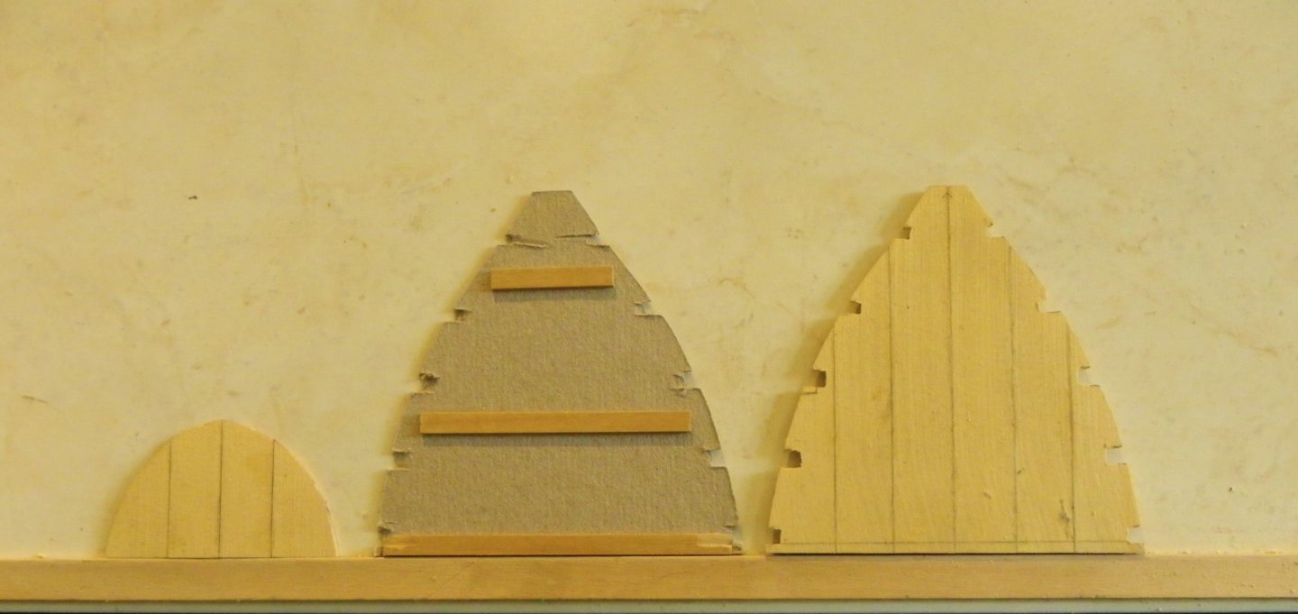
I followed the sensible approach of using card templates to mark the notches to fit over the frames before committing to the real thing.
Even so, fine tuning the notching proved to be a frustrating business.
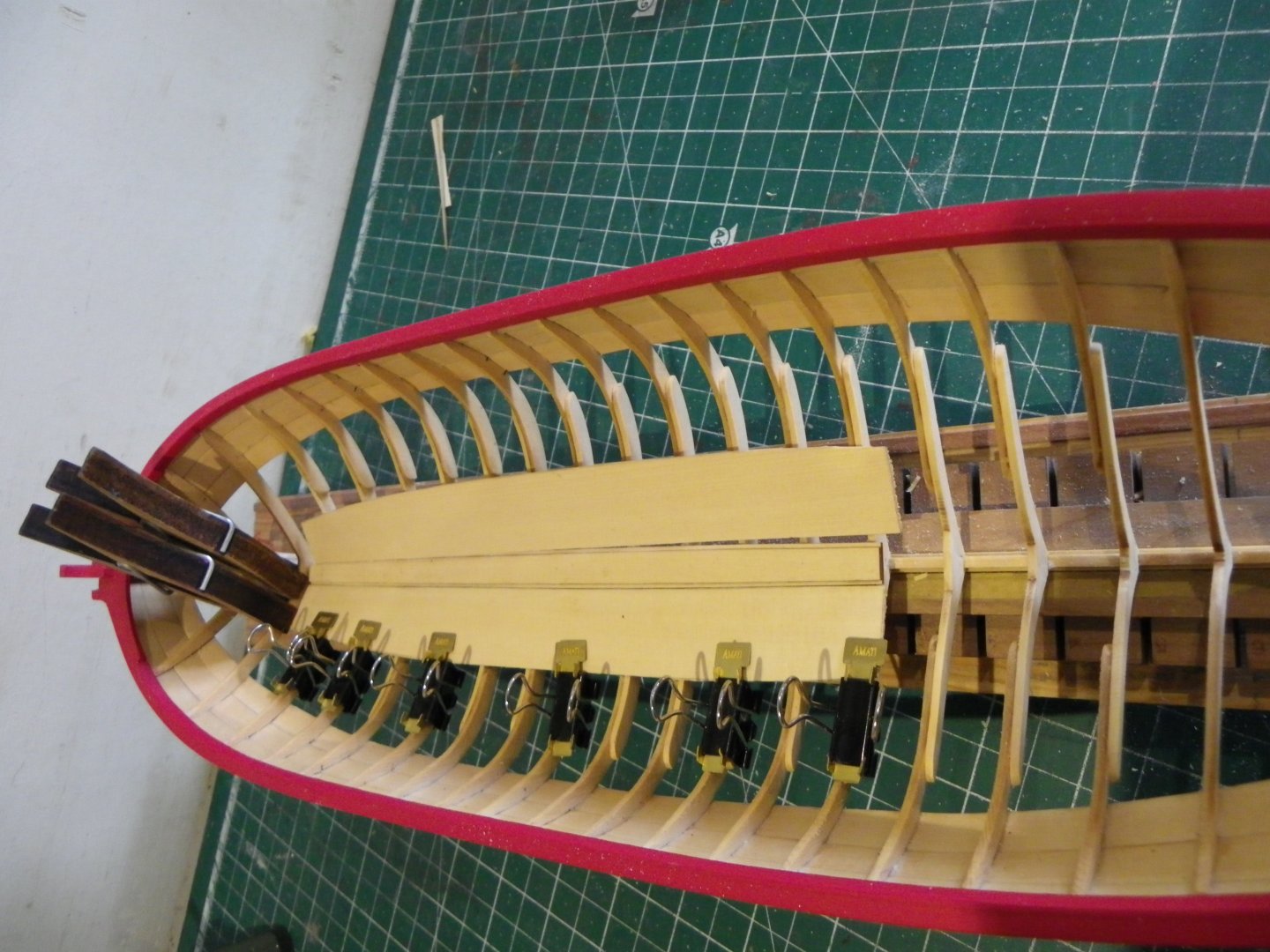
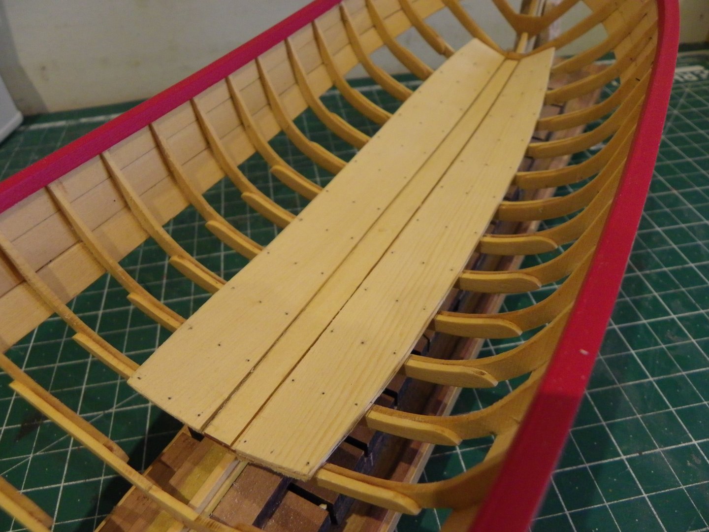
Chuck indicates that the platform should be ‘pretty low’ on the model, but how low is low?
0083
I made a simple height jig from the plan to gauge where the forward edge of the platform sat above the floorboards, and notched away until I got close to the level.

0088

2479a
0093
For me this involved cutting notches somewhat deeper than the guide photos indicated.
0087
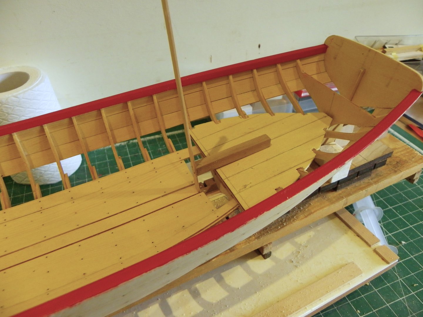
I hadn’t otherwise modified the boards at this point which seem to finish at the forward edge of frame seven from aft. Mine extended beyond frame 7 with a complete notch.
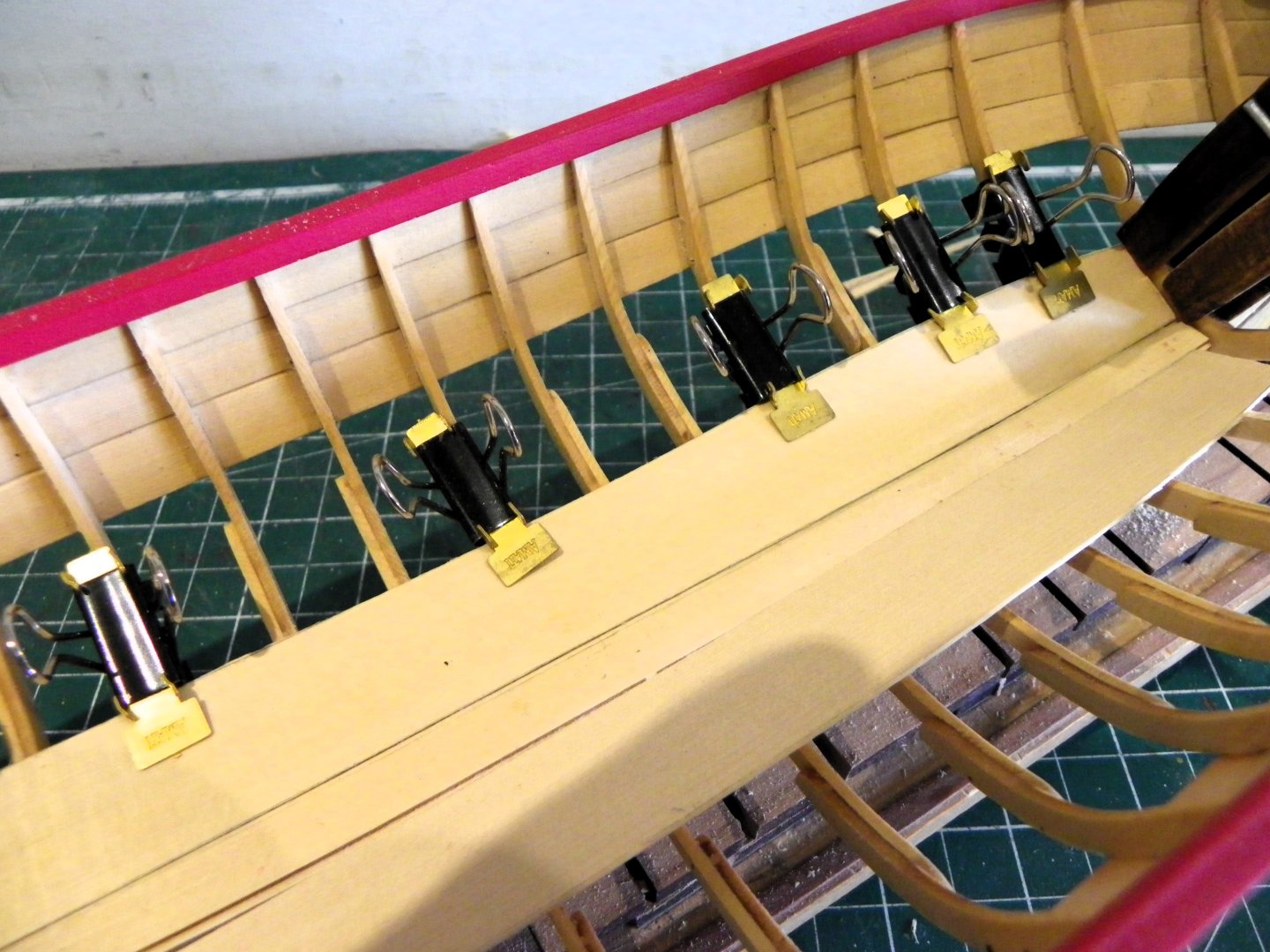
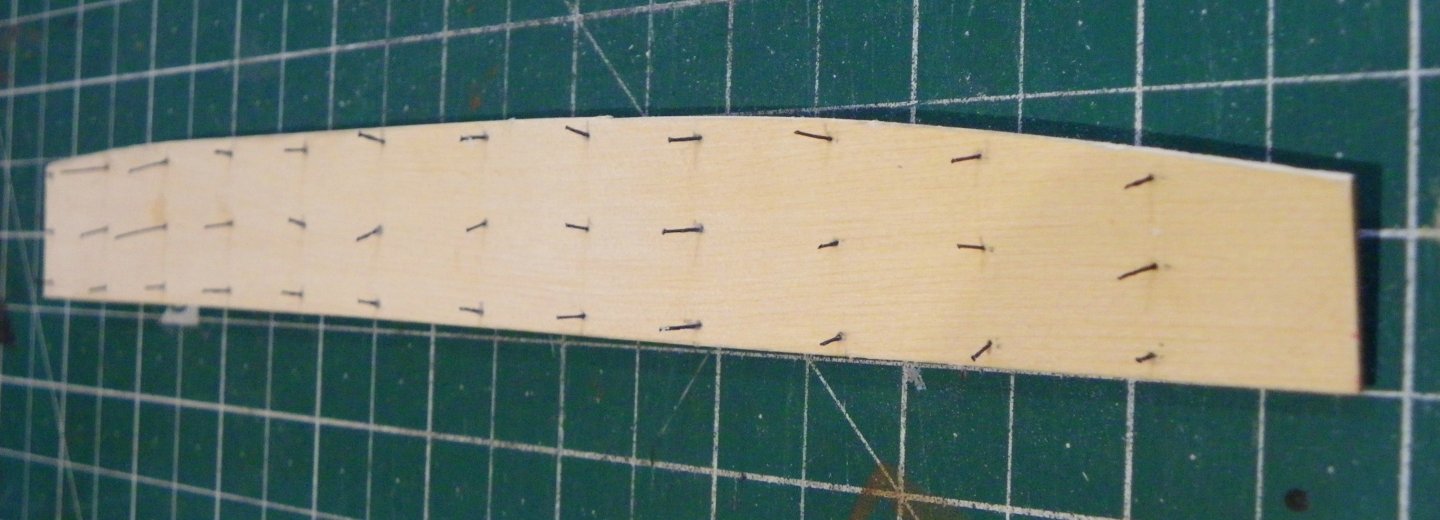
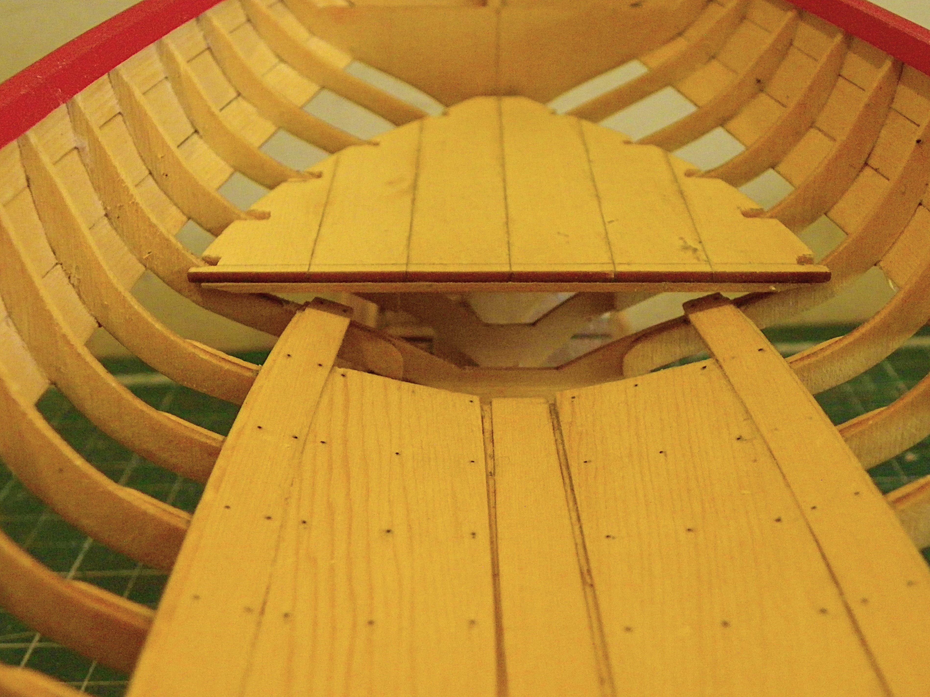
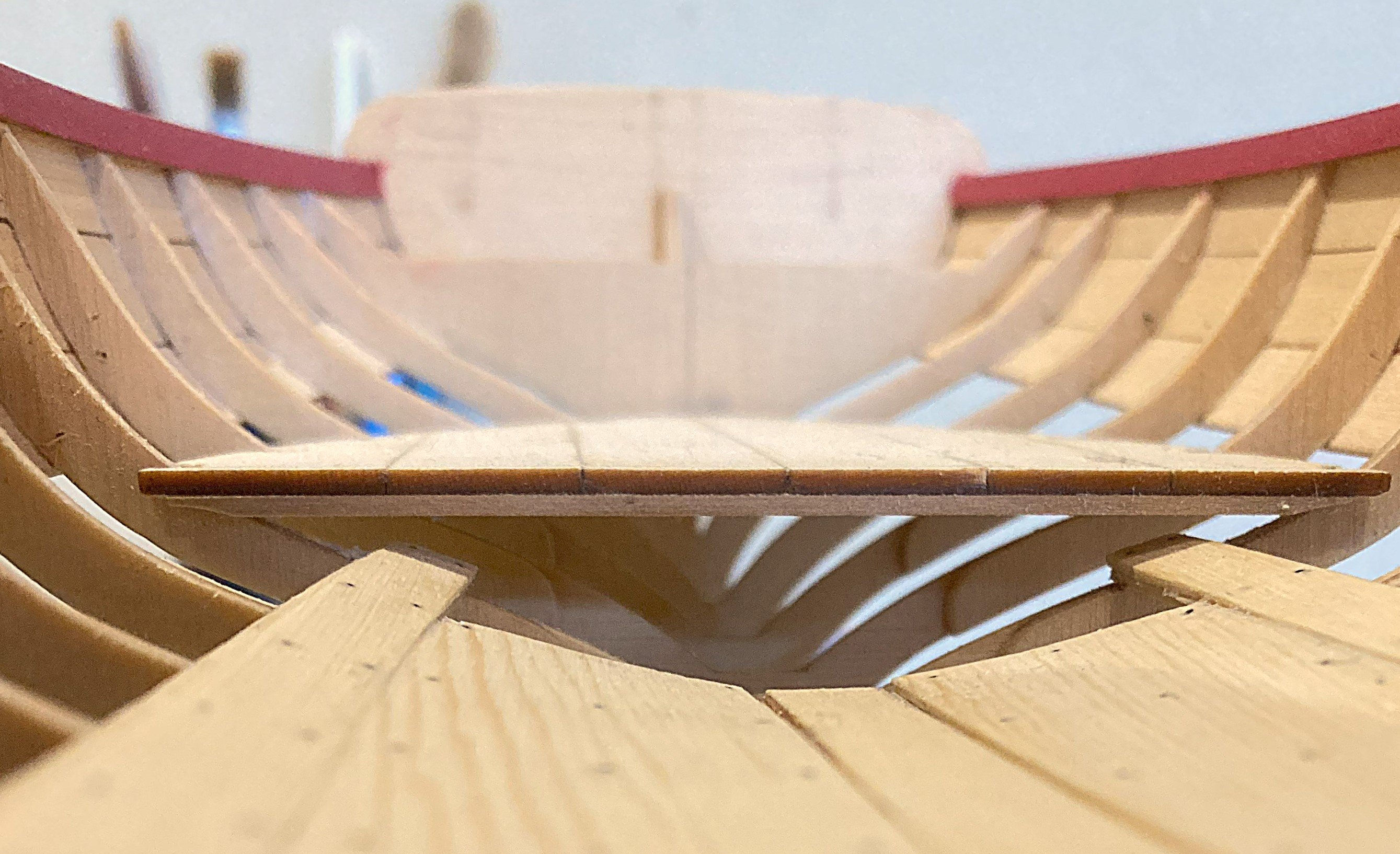
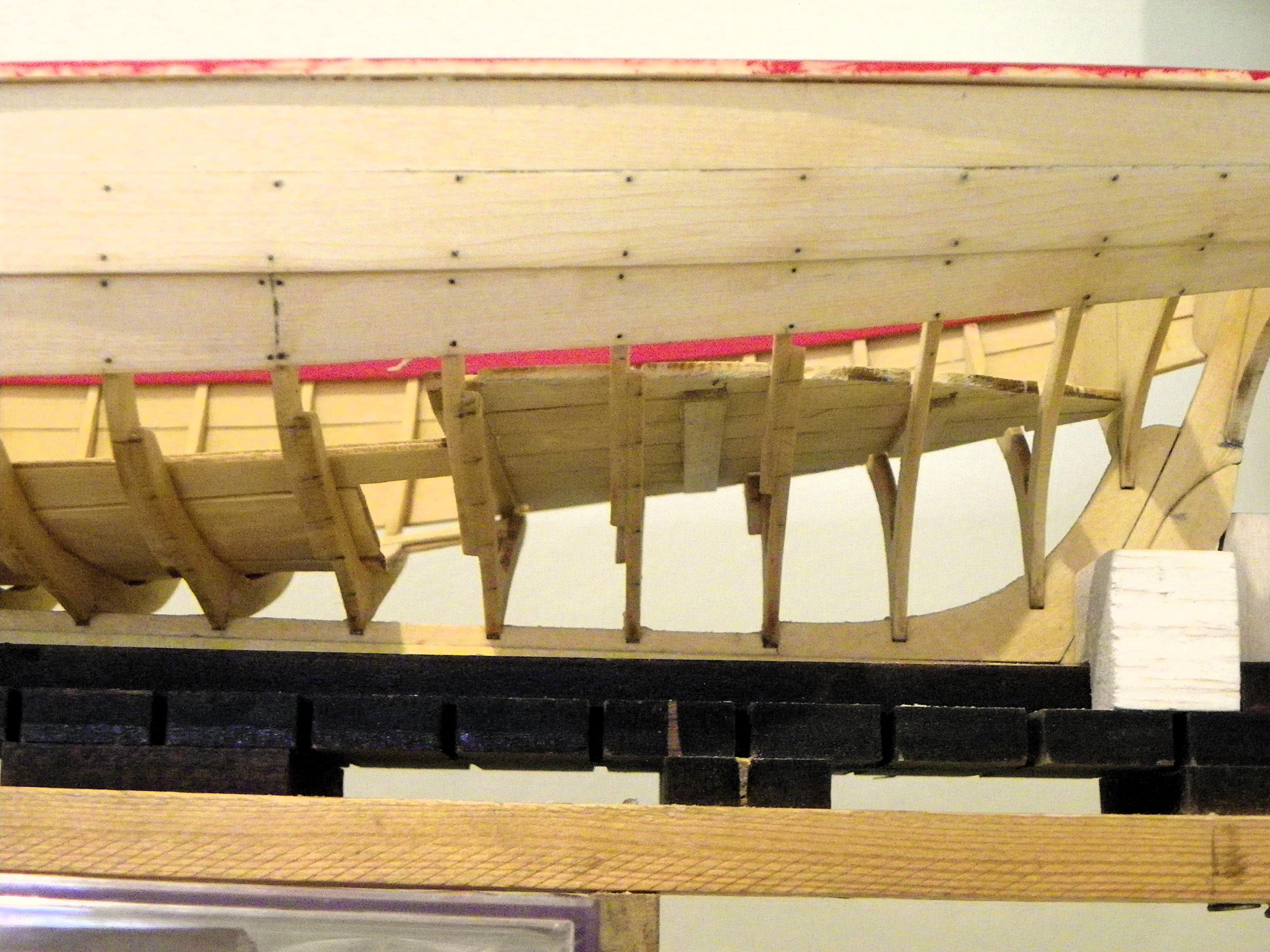
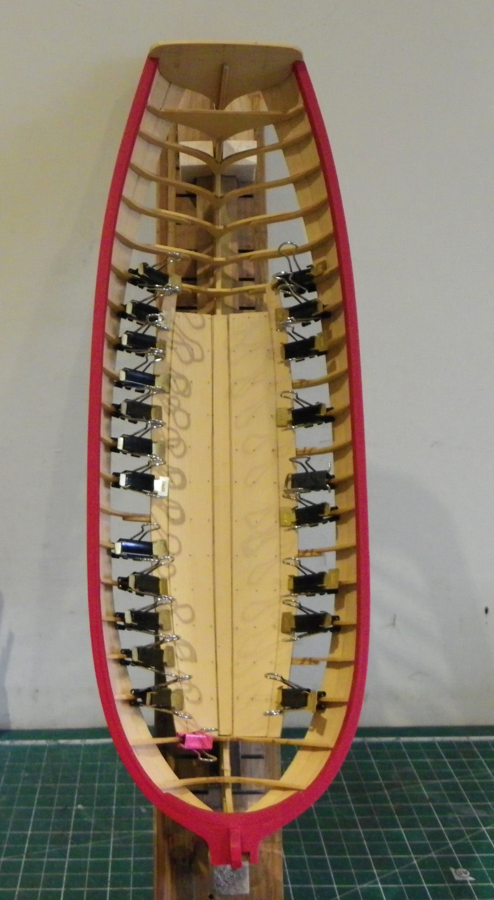
One final puzzlement I had with the platform was the nailing pattern.
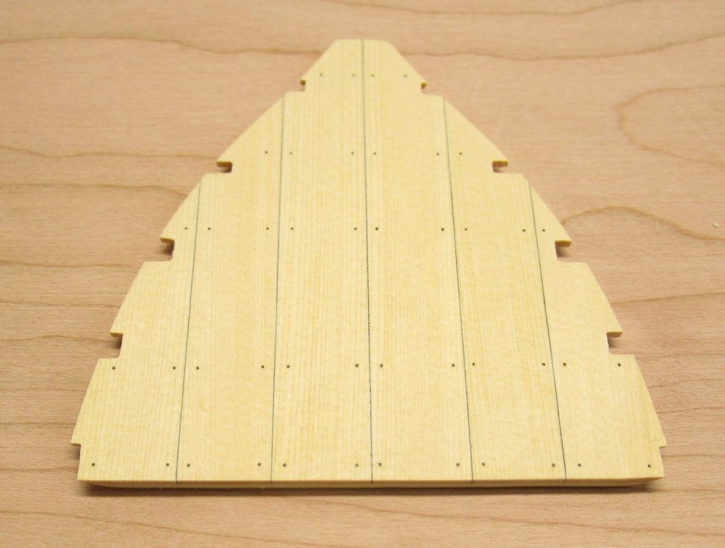
There are five rows of nails running across the planks, but to secure to what? There are no corresponding supports below these points.
Chuck has indicated the use of three random beams across the underside to secure the boards and provide lateral support but they bear no relation to the nail runs except perhaps for the fore-most one beneath the front edge.

0090
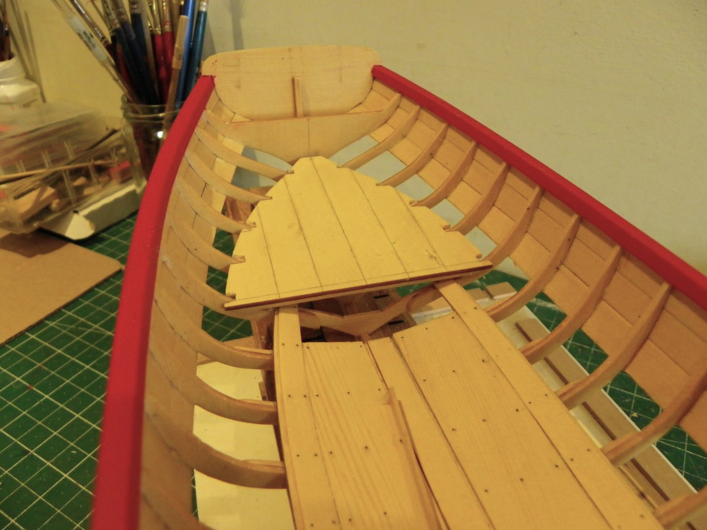
In terms of a fully planked version this has little relevance but for the open framed version what lies beneath is open to scrutiny, not a good look I think.
As the frames drop away from the boards with their ‘V’ shape, a more logical approach would seems to be to have support beams holding the planks together either in line with the frames or between them.
I think I need to change this.
B.E.
10/07/2024
-
Nice to see her set up for single banked rowing 👍
B.E.
- chris watton, Canute, hollowneck and 3 others
-
6
-
Well done on completing this behemoth Glenn, she certainly has presence as a fully rigged model. 👍
B.E.
- Ryland Craze and Glenn-UK
-
1
-
 1
1
-
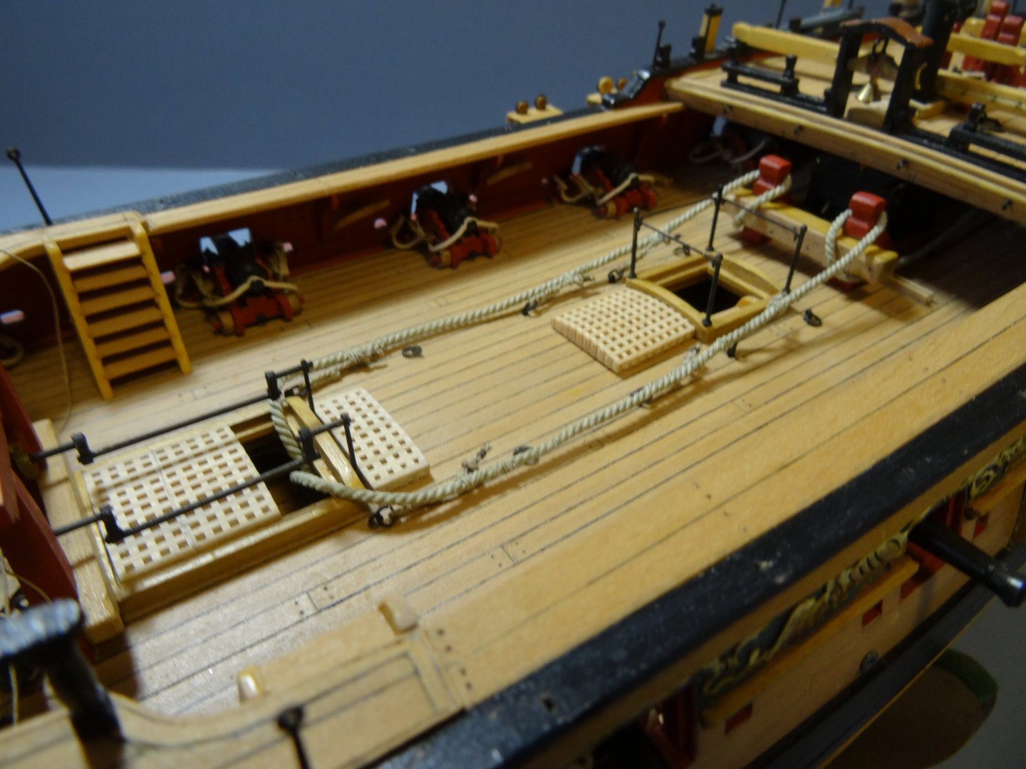
Anchor cable Rigging – Pegasus
I have been contacted a couple of times recently about the rigging of the anchor cables along the deck of Pegasus.
It seems I missed the inclusion of this element when I reconstituted my Pegasus log after the great crash.
So, for the benefit of any who may be interested this is a summary of my approach.
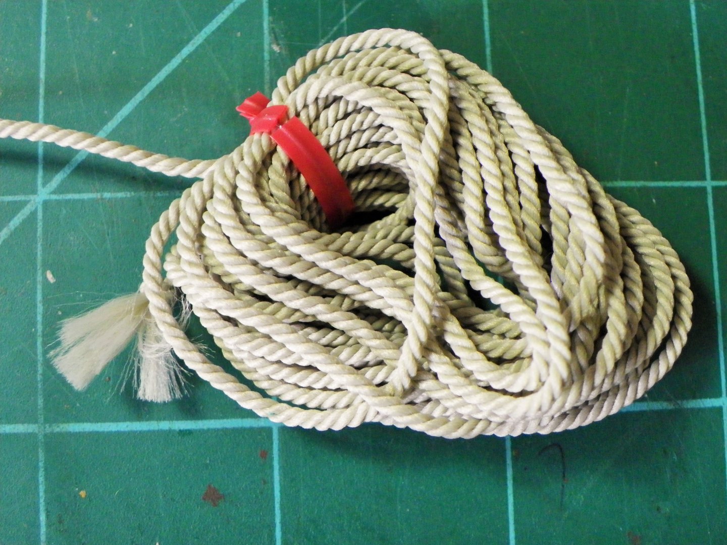
Anchor Cable.
The given size is 13" circ which scales to 1.64mm dia. I have gone for a slightly larger dia. preferring the look of Moropes 1.75mm stuff.
1983
As a nod to authenticity this is left hand cable laid rope, as it should be.
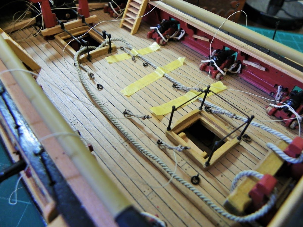
I considered how to pass entry down the Main Hatch;
Was the grating removed during the cable stowage process, or were there cut outs in the hatch grating to take the cables?
Something I missed from the early stages of construction tffm shows the Main hatch grating in three sections, so the forward one could be removed to allow passage of the hawser.
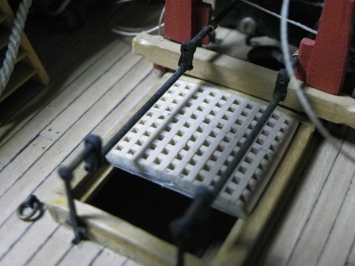
2010
The grating was modified to reflect this.

2091
One of the drawbacks of using non-natural Morope is the springiness of the line, which is a big disadvantage when it comes to things like anchor cables where an appearance of weightiness is desirable.
To counter this I immersed the line in diluted pva, followed by stretching to take the spring out of the cable before fitting.
2019
In reality the cables would be stored in the hold but of course there is no hatch on the lower deck. When I fit the cables they will be weighted and coiled neatly out of sight on the Lower deck.
If you are considering adding the anchor cables to the model, beyond simply stuffing the rope ends into the hawse holes, early consideration should be given to the Main hatch gratings.
Stoppers
While the Riding Bitts took the majority of the stresses on the cable of a ship at anchor, additional security was provided by use of stoppers attached to ring bolts in the deck and seized to the cable inboard of the Bitts.
According to Steel these are the proportions of the stoppers.
Cabled 7" ( 0.88mm ø ) Finished length of short stopper before fitting 8' 3" (39mm at scale);seizing with 1" (0.1mm ø) line. attached to cable with a 2" (0.25mm ø)lanyard
There are six stopper ringbolts each side of the deck.
These were made from brass rings and eye bolts clenched together and blackened. These ringbolts also doubled up for the relieving tackles of the Upper deck guns.
This is what Steel has to say about stoppers.+
STOPPERS. Short ropes, used to check the cable, suspend weighty bodies, and retain the shrouds, &c. in a fixed position, after being damaged, or otherwise. ANCHOR-STOPPERS are used to suspend the anchor, when catted: BITT-STOPPERS are those stoppers used to check the cable: DECK-STOPPERS are used to retain the cable when the ship is riding at anchor: DOG-STOPPERS are used as additional securities when the ship is riding in heavy gales, or bringing up a ship with much sternway, to prevent the cable from snapping at the bitts, and to ease the deck-stoppers: WING-STOPPERS are used for the same purposes as dog-stoppers: SHROUD-STOPPERS are used to confine a shroud together, when damaged, or shot. FORE-TACK, and SHEET, STOPPERS, are for securing the tacks and sheets, till belayed.
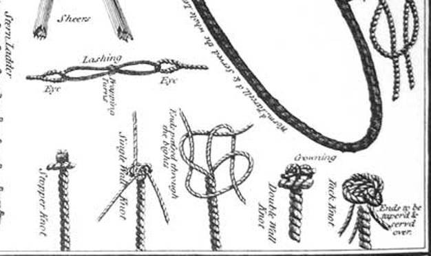
STOPPERS, DECK and BITT, are divided into ten short and two long stoppers. The two long stoppers, from a first rate ship to a sloop, are cut sixteen feet; and, when knotted, to be twelve feet six inches. The short stoppers are each cut twelve feet six inches; to be, when knotted, eight feet three inches long. One end of each stopper has a double wall-knot, and the ends led up through the middle, and whipt with spunyarn: the other end is only whipt with spunyarn.
PREPARATIONS NECESSARY TO BE MADE FOR ANCHORING.
On approaching an anchorage, the anchor and buoy are got clear, and a range of cable stretched along the deck suitable to the depth of water. Care should be taken, that nothing is in the way to check the cable, or stop its running out: then, at a proper distance, a turn is taken round the bits with the cable, thus: First pass the cable from the anchor underneath the cross-piece, then take up a bight of the cable abaft the bits, and throw it over the bit-head. The end of the cable is clinched round the orlop beams in the royal navy, and round the main-mast in the merchant service.
It is necessary to have water near the bits to prevent its firing by the friction. Stoppers and ring ropes of all kinds should be ready for use. The stock lashing being cast off, and nothing but the anchor stopper and shank painter retaining the anchor, men are stationed to stand by them, and let go at the moment ordered.
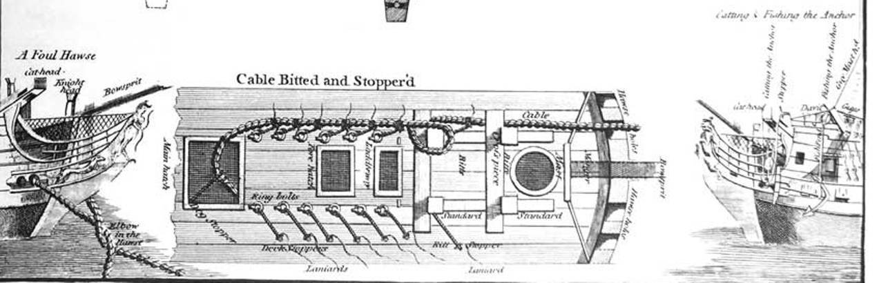
To secure the cable when out, DECK STOPPERS are thus previously prepared: they are turned into the ring bolts on the deck, round a large iron thimble, and fastened with a throat and end seizing. Each stopper has a laniard spliced round the head, under the knot, by which several turns are taken round the cable, and the end stopt.
BESIDES the deck stoppers, others are used as an additional security to the cable; such are the BIT STOPPERS, &c.
BIT STOPPERS. Each stopper is reeved through a hole in the standard knee, against the fore part of the riding-bits, and is turned in or spliced. It has a laniard spliced round the head, under the knot. When used, several turns are taken with the laniard round the cable, and the end stopt. It is to check the cable in bringing up the ship. Another bit stopper much approved of, is about four fathoms long, and tailed out like a nipper at one end, and knotted at the other. Let this stopper be rove through the hole in the standard knee. To pass it, let it be held aft, inside, over the cable, and under the bits, outside the cable; then worm it round the cable before the bits. Then, as the cable runs out and it is required to check the ship, haul tight the worming; and, by the cables drawing forward, it will tighten the stopper, and bend the cable so close to the bits as effectually to bring the ship up. This stopper is not likely to jamb, Therefore is extremely well calculated for bringing a ship up with ease; as, by slacking, and hauling tight the worming, the cable may be suffered to run out, or be checked at pleasure.
In heaving up in a heavy sea, when, by a sudden pitch of the ship, the messenger or nippers give way, this kind of stopper will be found extremely serviceable; for, upon these occasions, this stopper may be always passed ready, and the bight triced up abaft the bits, with a rope-yarn clear of the cable.
Another bit stopper, made with a large eye, that it may be thrown over the bit head, and shifted over from side to side, is also much approved of.
DOG STOPPERS. One end is clenched round the main-mast, and the other end wormed in the cuntlines of the cable, and stopt in several places; then brought back with several turns over its own part, and the end stopt. It is of little service, unless it be long enough to clap on above the coamings.
WING STOPPERS. One end is clenched round the orlop beams in the wings, and the other end is clapt on as the dog stopper.
RING ROPES are occasionally made fast to the ring bolts in the deck and to the cable, by passing the ends through the ring of the bolt, and through the bight, then clapt on the cable with cross turns, and the ends stopt. Ring ropes may be better single than double; they are passed with less confusion of turns. To pass a single ring rope, and have it in readiness to check upon veering away the cable, take also three slack turns through the ring bolt and round the cable, one before the other, and hold up the parts fair; then take as many slack turns of worming round the cable, before the ring, and they held up fair, leaving sufficient room for the cable to pass through. When the cable is to be checked, haul tight the worming; and by the cables running out, it will readily draw the turns tight through the ring, and bind the cable so close to the ring, as to prove an excellent stopper. Ring ropes are similar to the laniards of stoppers, to check the cable when freshening the hawse, or to add security to the stoppers in a heavy sea.
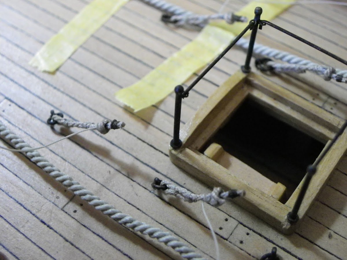
For the stoppers I am using Chuck's tan rigging line .035" which conveniently scales to 0.88mm ø spot on for 7" circ. cable.
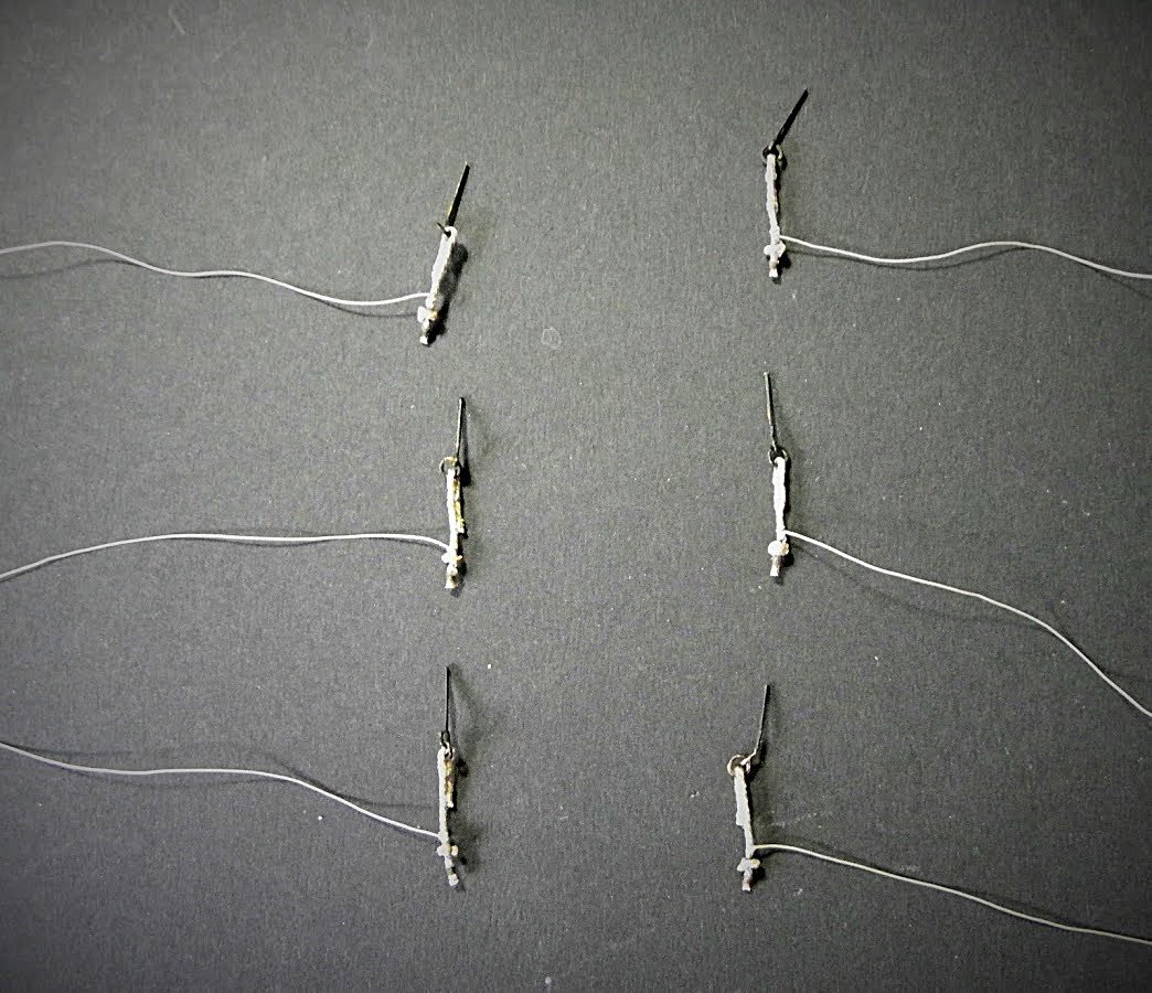
2131
The first job is to attach the stopper to the deck bolt. It should be turned into the ring of the bolt using an iron thimble and finished with a throat and an end seizing.
I use a needle to work the seizings of 0.1mm line.
Good job I hadn't glued the ring bolts in place.
At the scale involved for me at least, I don't think it viable to represent the thimble as it would be very small and thin inside the bight of the stopper line, the throat and end seizings present no difficulties.
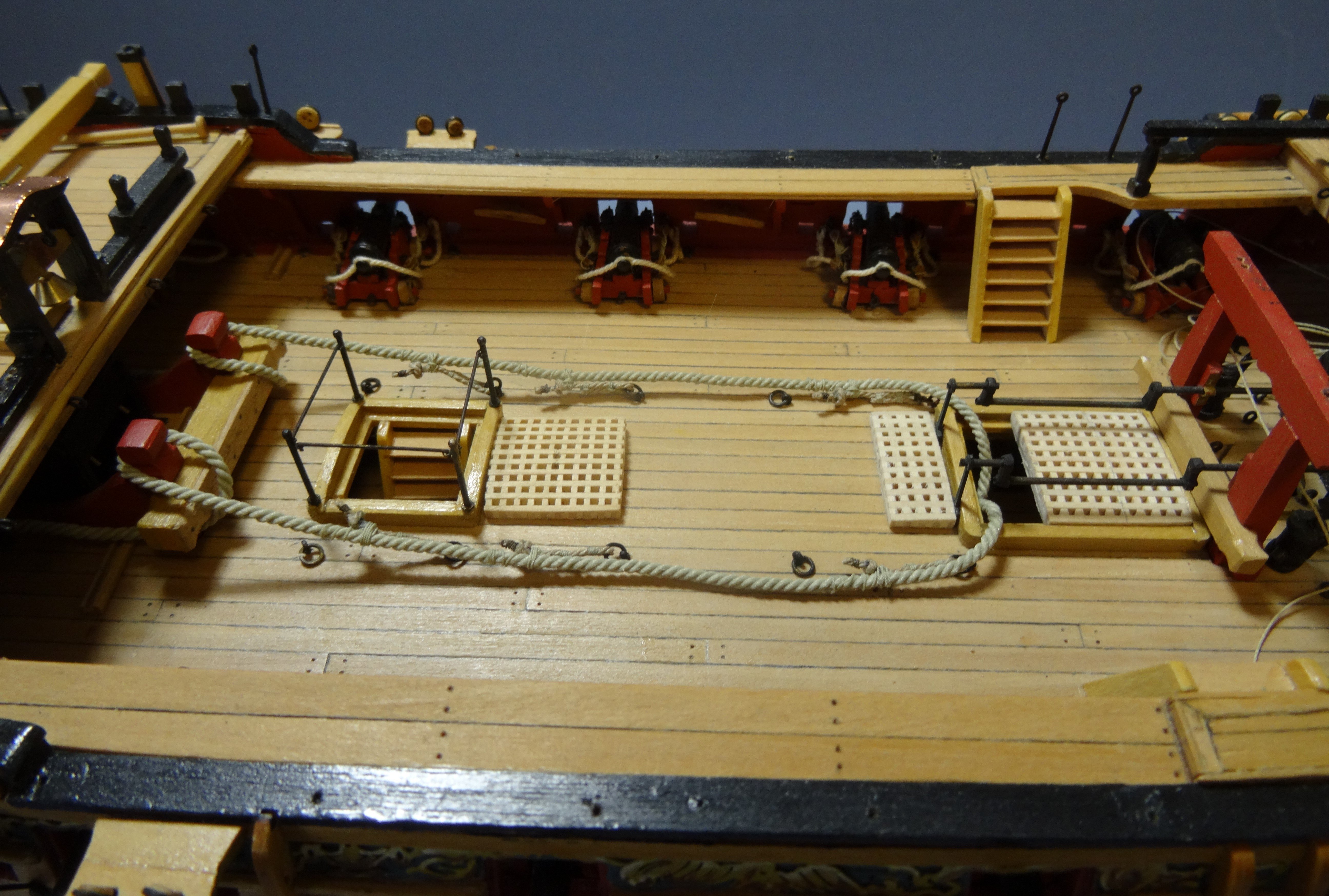
I decided to fit three stoppers each side, partly to demonstrate the purpose but mainly to secure the anchor cable and keep it taut from the Bitts to the hatch.
To determine the length of the stopper I did a temporary fit against the anchor cable and marked off the length.
The next real tricky problem is how to represent a Matthew Walker knot at the end of the stopper.
Having looked at how you form one of these, I dismissed trying it in a nano second, there are far simpler ways of driving yourself mad.
So, this is my approach:
Take some of the stopper cable and soak it in diluted pva. Form a very tight ring and slice it where the two ends cross. Immediately seal the cut ends with ca.
Using ca apply the ring to the stopper and use more ca to glue the two end of the knot together.
This is the result.
2141
At scale I think the knot looks ok, the overall length of the stopper is only 15mm.
2140
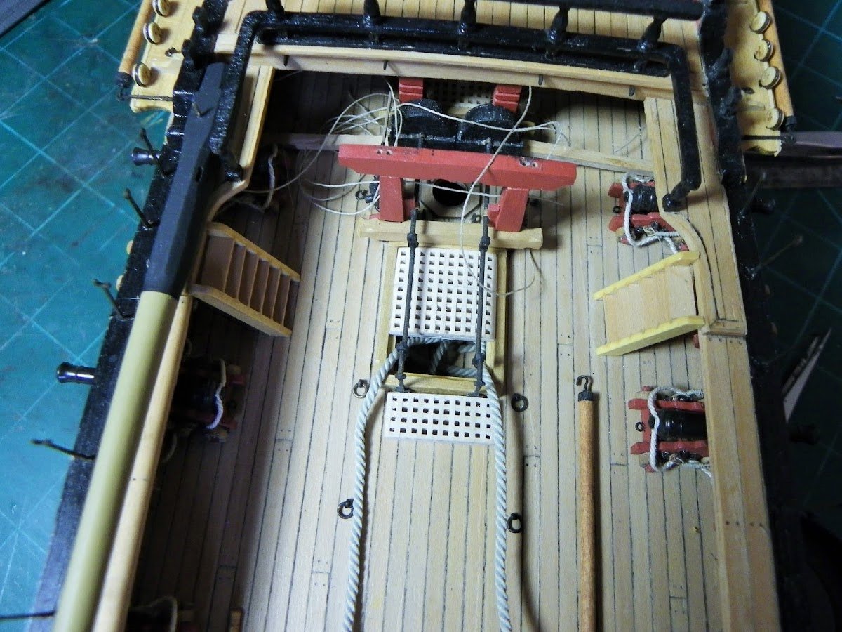
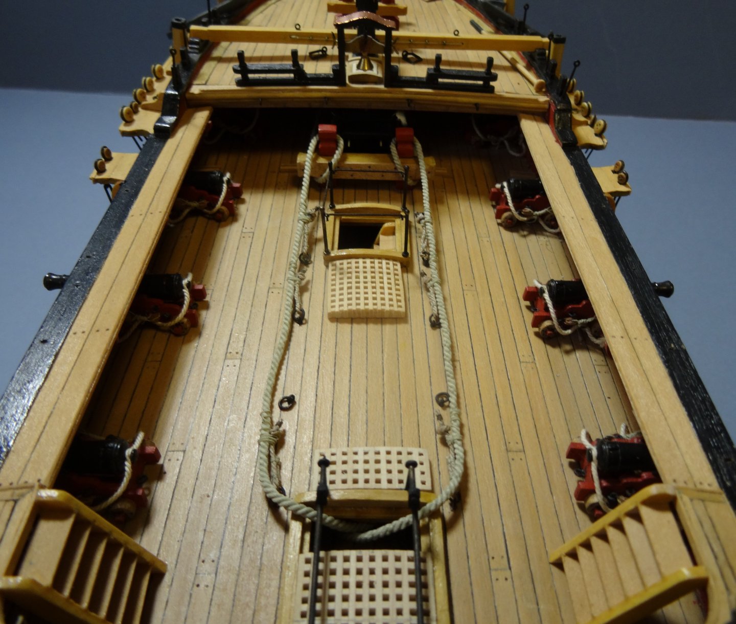
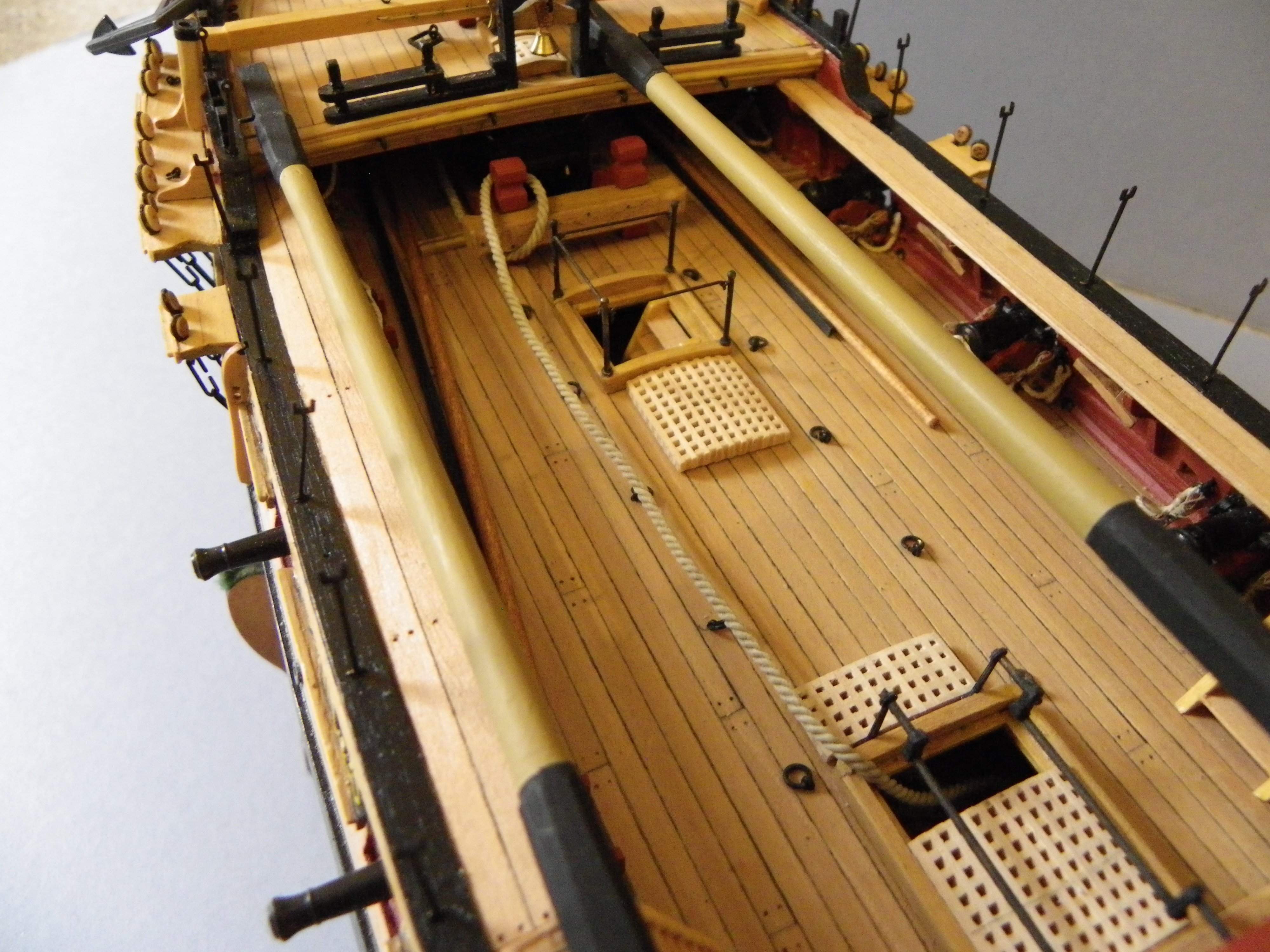
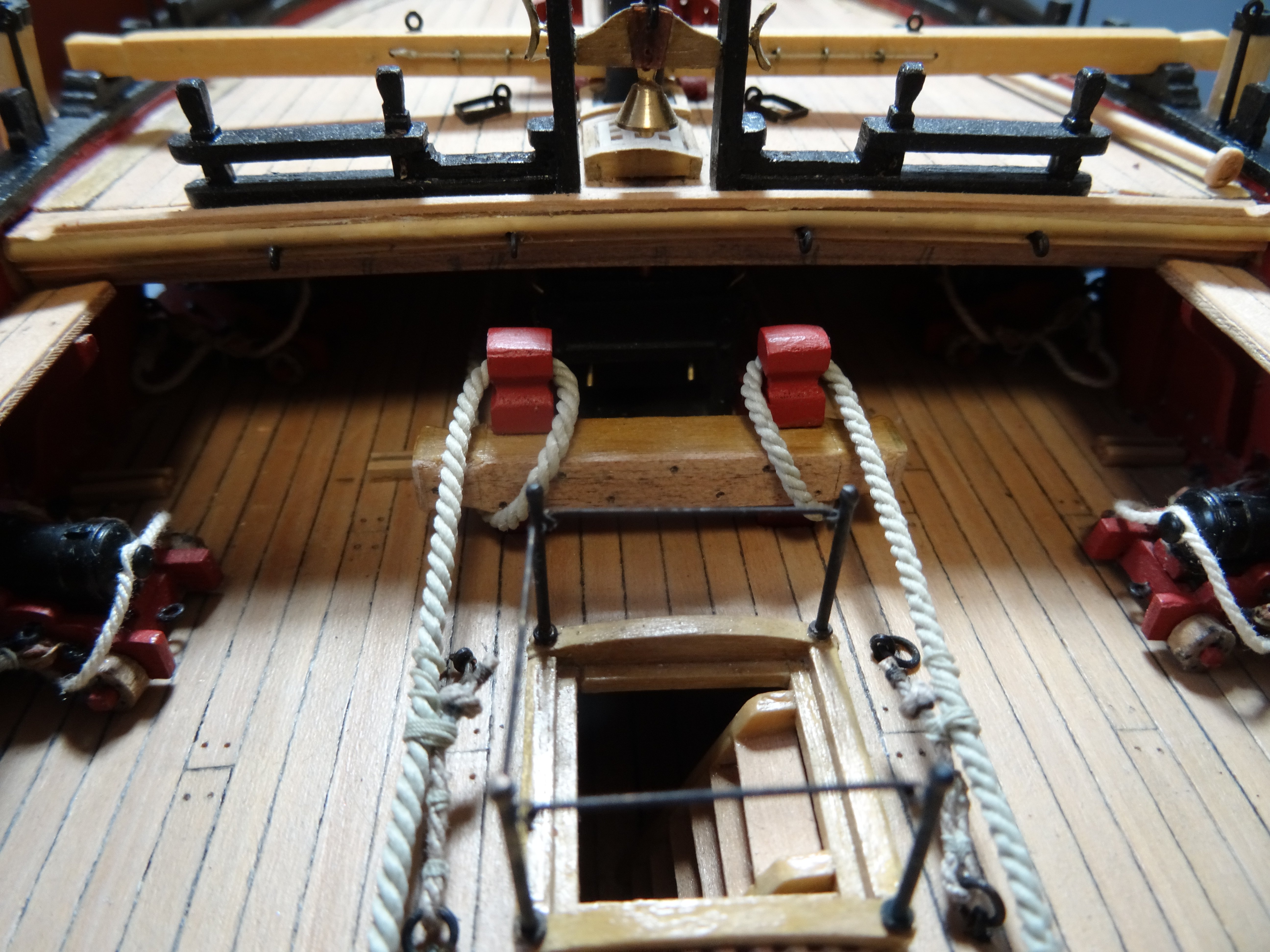
The anchor cable is secured along the deck for fitting of the bitts.
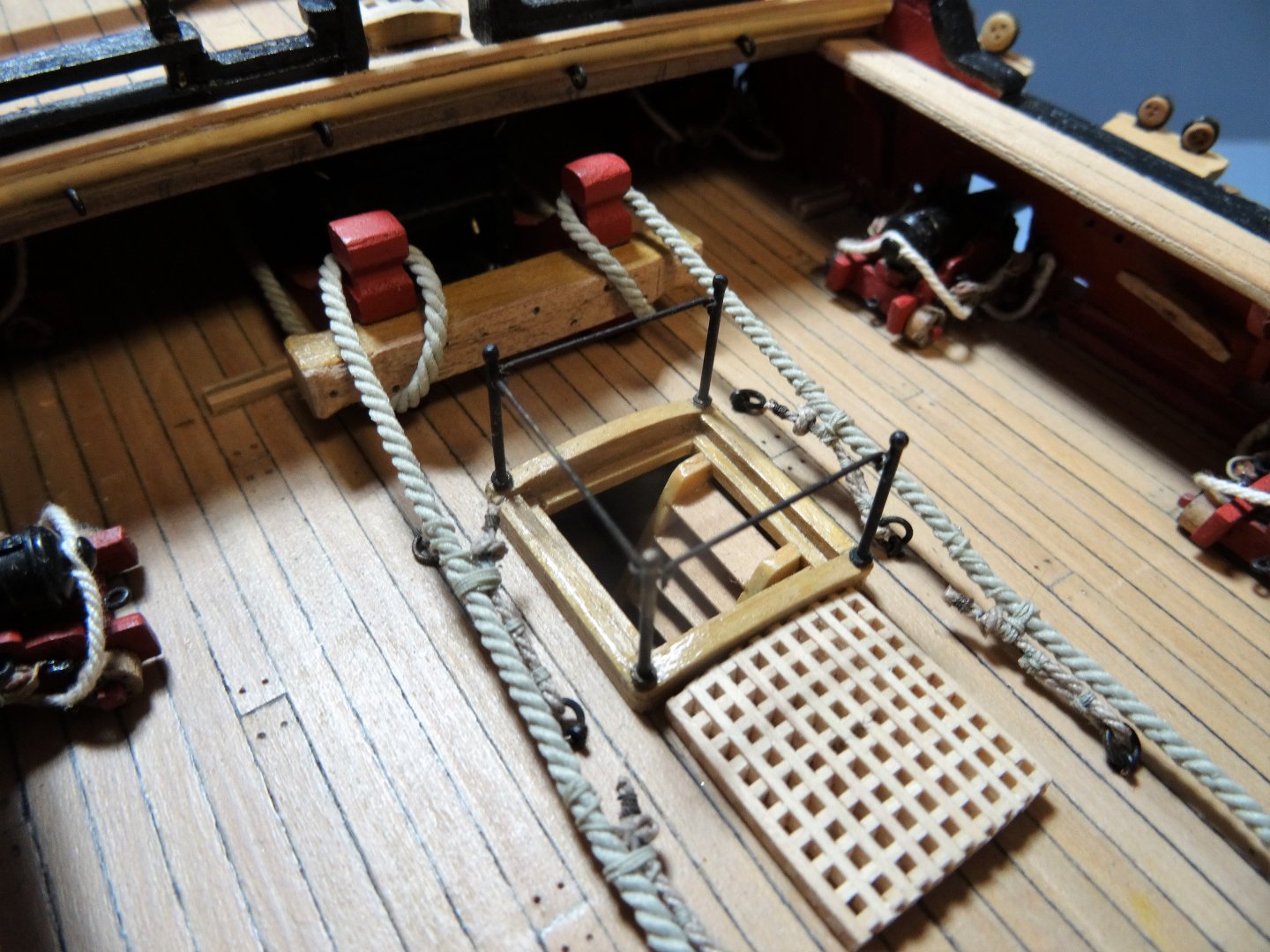
8989
09000
Constant minor adjustment to the cable and the stopper is required as it is seized to the cable, to keep things looking reasonably taut.

8990
8992
8993
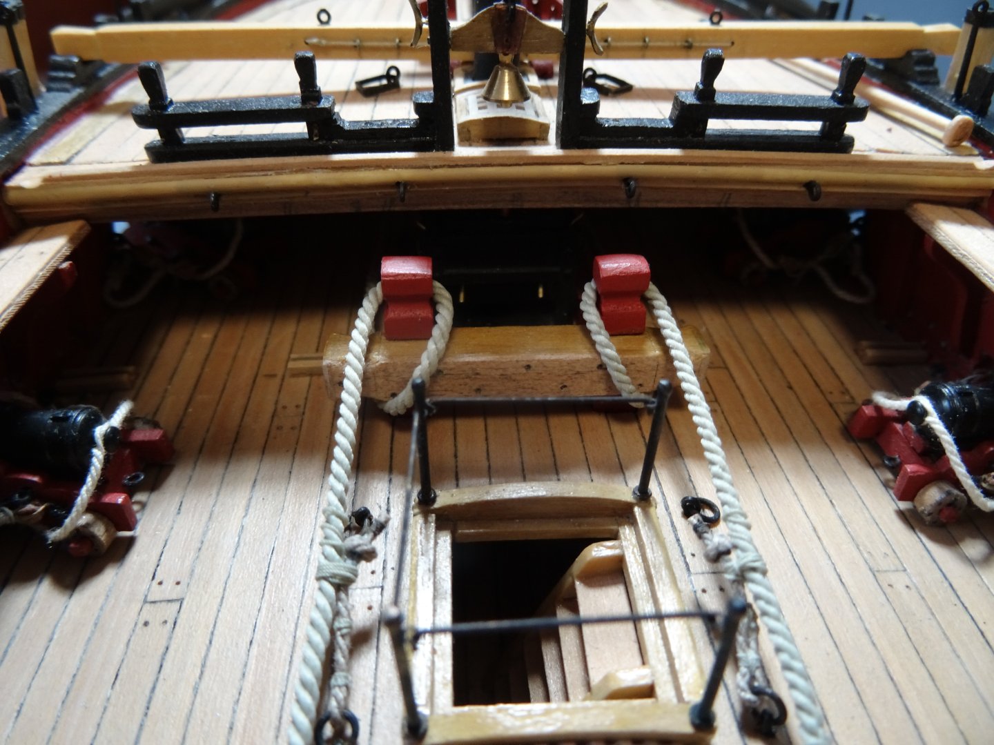
The anchor cables are coiled and secured between the frames below decks. Note they are crossed as they enter the hatch, this was an accepted practice to make handling easier, and in modelling terms it also allows a better lay of the cable.
So, if you're thinking of attaching the cables to the anchor this job needs to be done at a no later stage than this to avoid access problems on the model.
Note:
This arrangement is stylised in the sense that the anchors are at the cathead but I'm showing the cables around the riding bitts and secured along the deck with stoppers. Securing the anchors like this would normally be when the ship is at anchor, and the stoppers are to relieve the strain on the bitts.
My intention was simply to add interest to the deck details whilst showing how anchor cables were secured.
B.E.
08/07/2024
- hollowneck, davyboy, BLACK VIKING and 7 others
-
10
-
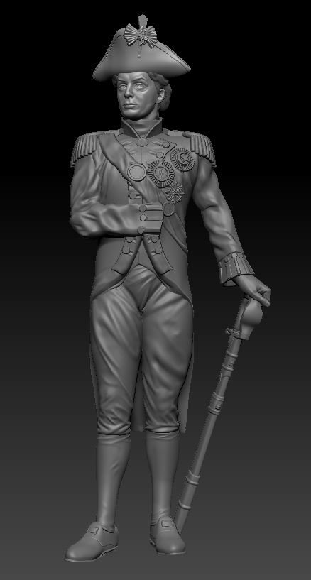
A new Nelson figure has been created by Chris.
- BobG, hollowneck, Nirvana and 8 others
-
11
-
An interesting project.
Danish sterns had a very different look to those of British ships which should clearly mask the Sphinx origin. Replacement of the Sphinx figure, not the prettiest of features, is a bonus.
A bit of kit bashing is right up my Strasse, and I wish you well with your endeavours.👍
B.E.
- davyboy, TJM, hollowneck and 2 others
-
5
-
I'm in, thank you for pressing on with this project.👍
B.E.
-
Love the look of her David, very nicely done. 👏
B.E.
-
Interesting times ahead Chris, and best wishes for the fruition of your plans.
B.E.
-
I think your biggest achievement is your obvious enjoyment of a first build, recognition of areas that you hope to improve, and an appetite gained to build another.
Well done.👍
B. E.
- TJM and Thukydides
-
1
-
1
-
Old news Glenn, the project is back on for one last throw of the dice. 👍
I rather think your description of the figure set as small plastic toy a little unkind and dismissive of the hard work that no doubt goes into creating such items.
B.E.
- Old Collingwood, hollowneck, Nipper and 4 others
-
7
-
I would urge Chris to reconsider his decision and proceed with this project, it has the makings of being a unique and interesting addition to his range.
I was looking forward to making a dio around the figures as I did with the cook figure at 1:48 scale, in addition to having a sitting figure to have in the Great cabin of my 1:64 scale build.
There are going to be a lot of disappointed people, and I'm one of them.😞
B.E.
- thibaultron, mtaylor, DB789 and 7 others
-
10
-
The reason I asked is because I was thinking about retro fitting to my existing 'Indy' model.
B.E.
- thibaultron, mtaylor, Canute and 1 other
-
4
-
A big improvement Chris, the standing figure looks just like Rupert Penry-Jones.
Is the sitting figure separate to the table/chair, and scaled to fit your existing furniture designs?
B.E.
-
An excellent rendition of an oob build, very well done James.
She surely looks impressive as a fully rigged model.
B.E.
- Dave_E, Craigie65, Ryland Craze and 4 others
-
7
-
I'm not too sure about the rear view of the standing figure, there seems to be an unnatural look to the upper body, and the coat looks odd without tail vents, as per the sitting figure.
B.E.
- druxey, thibaultron, Canute and 2 others
-
5
-
What I've been waiting for, thank you Chris.
Presumably there is more work to do on the figures before they go into production?
B.E.
- thibaultron, Canute, Craigie65 and 3 others
-
6
-
-
-
Post 23
Completing the boarding.
The outer boards, one each side are a construction of two 1/32nd strips, one atop the other leaving a rabbet on the outer side.
As with the wide boards I opted to glue the base layer first followed by the top layer.

0071
There was a degree of fettlin’ to get the planks tight against the broad planks, and an even rabbet along the outer side.
The nail positions were marked with the top planks in situ and removed for the drilling and ‘nail’ insertion.
0076
0075
On completion a coat of w-o-p was applied.
Moving onto the platforms.
B.E.
05/06/2024
- CaptnBirdseye, CiscoH, JeffT and 4 others
-
7
-
-
When I came back to the build I re-read Chuck's log and many others, to refresh my memory. I consider myself lucky that I have all these excellent builds, including yours Bob, to refer to.
I picked up the tip of using the thinner stuff from Chuck's log, but it's not mentioned in the download instructions.
I was concerned about using too much pressure on those open frames.
B.E.
- BobG, CiscoH and Ryland Craze
-
3
-
Post 22
Fitting the boards
Initial fitting of the 1/16th broad plank reveals it will be a tricky part to fit.
It is clear that a gentle approach will be required in getting the boards to conform to the frames as they are far more vulnerable without the support of outer planking.
Chuck had suggested that the broad planks could be cut from 1/32nd sheet and glued one on top of the other in the same manner as the outer planks.
These would better conform around the inner framework, and
having played around with the 1/16th board I decided that the 1/32nd option was both easier and safer.
Not out of the woods yet;
Shaping by degrees was needed on the inner side of the broad planks to cleanly meet the central one.
Additionally, I had problems with Frame ‘F’ - third from the bow, which needed additional fairing to allow the board to sit down properly. This frame was also troublesome with the central plank.
0040
0042
These Amati planking clamps are ideal for securing the boarding both for heat treatment to conform the board, and for eventually gluing.
This would not be an option with a fully planked hull.
It is the forward section of the boards that require some twist to conform to the forward bow frames but using 1/32nd board there is no problem.
0049
The base layers in place.
0045
Here the port side second layer strip in position for the application of the heat treatment. Spacers are used to maintain the rabbet line on the central plank.
Before finally gluing into place the nail points were marked on the planking and pre drilled.
I used a 0.4mm drill.
Care is required to ensure that the nail lines across the board are even and square to the frames.
With the board in place I drew fine pencil marks in line with the frames, and off the model I marked the nail positions and drilled.
The board then needed cleaning with isopropanol to remove the traces of the pencil marks.
0054
Using 10lb fishing line the ‘nails’ are inserted, secured with pva. Dull work, but I can’t complain given that I have been spared the bulk of this task.
0055
0059
0057
0056
Onto the outer boards.
B.E.
03/06/2024
- gjdale, chris watton, Ryland Craze and 8 others
-
11


Medway Longboat 1742 by Blue Ensign - FINISHED - Syren Ship Model Company - ½” scale
in Medway Long Boat - 1742 - Public group project.
Posted
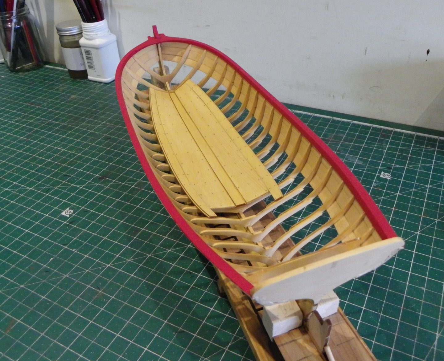
Post 25
Platforms continued
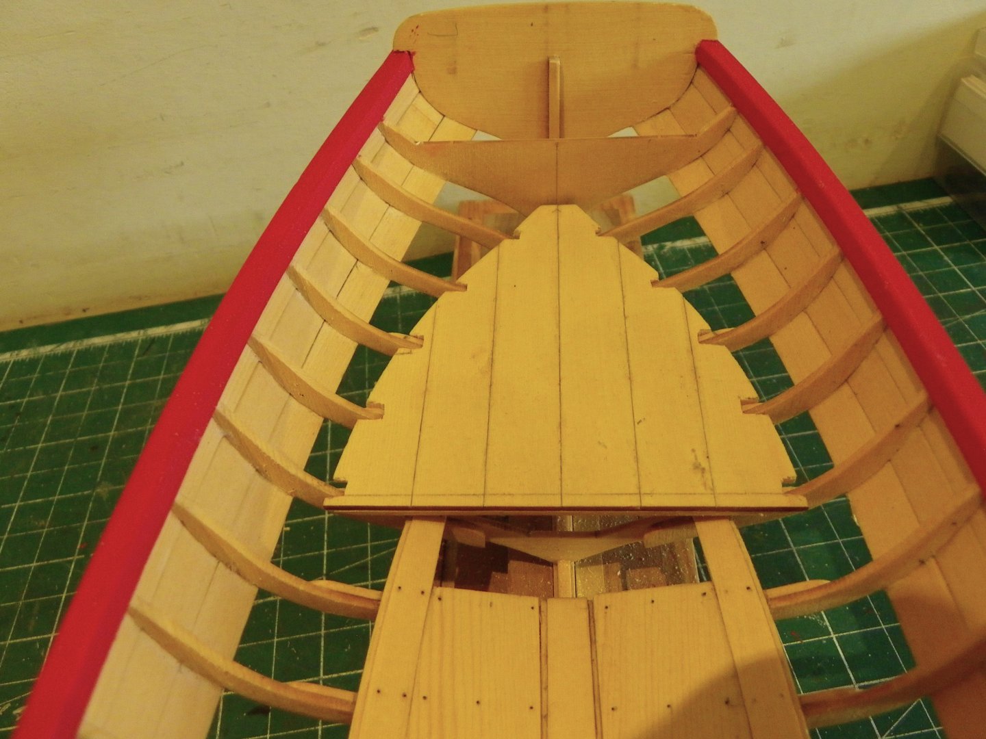
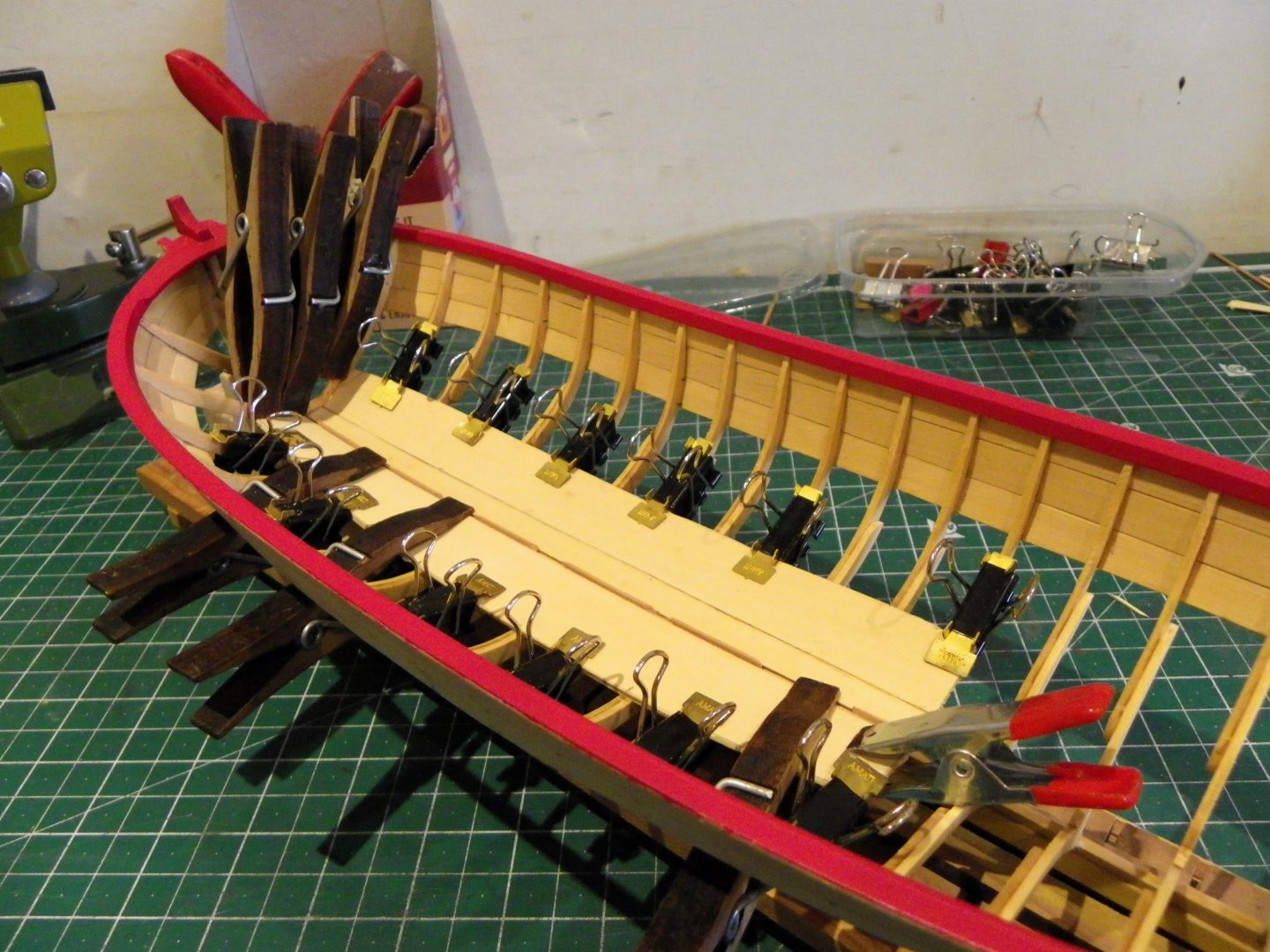
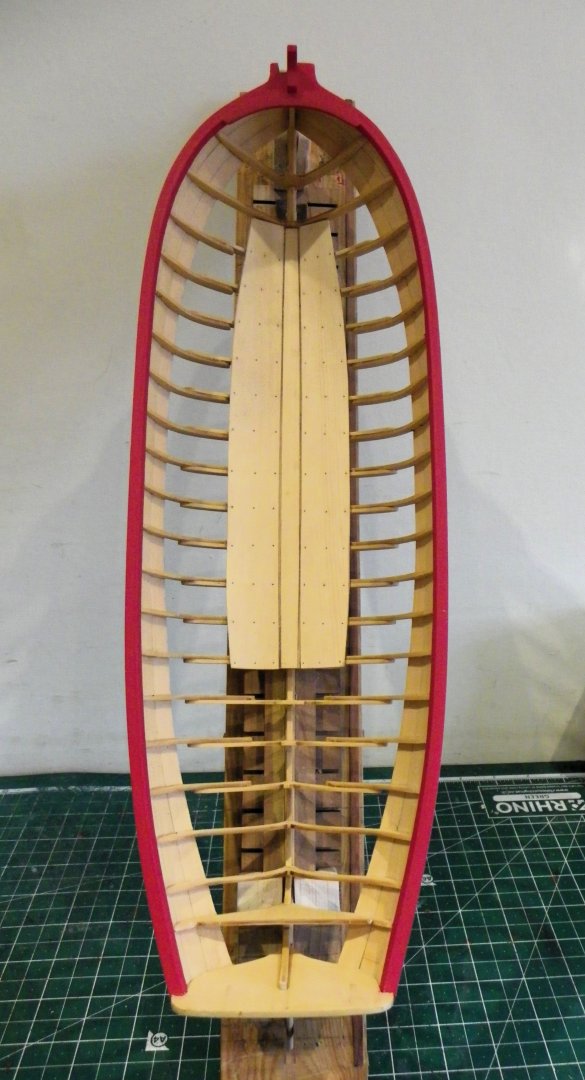
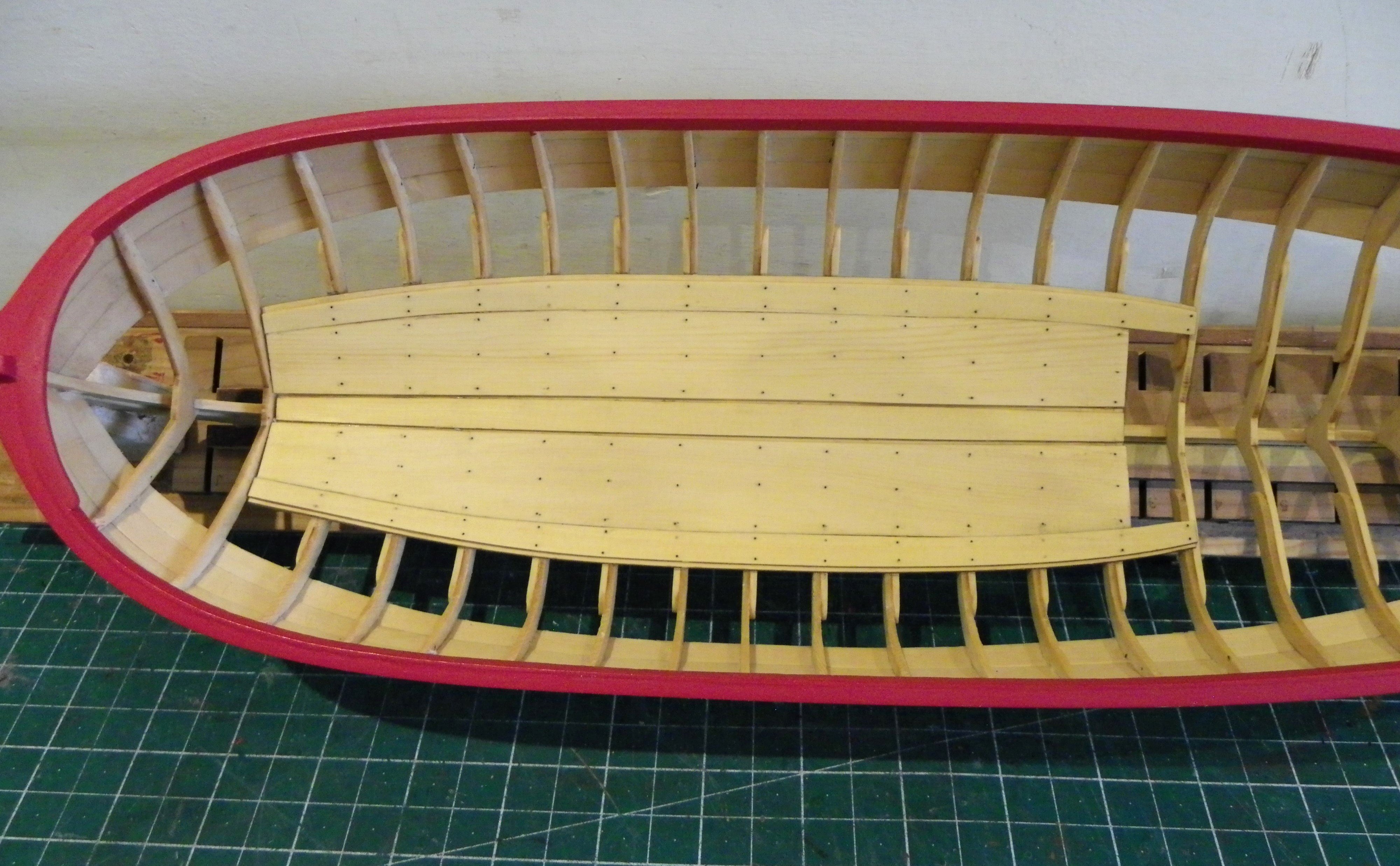
Modification of the aft platform has been made.
0095
The forward end has been trimmed to create a half notch and support beams added to fit adjacent to the aft sides of the boat framing.
0096
For these I use 3.3 x1.3mm strip that I just happened to have in stock.
Each beam was pva’d into place and the nail points marked.
0111
Using 10lb fishing line the ‘nails’ are inserted, secured with pva.
0125
0124
0113
0116
0118
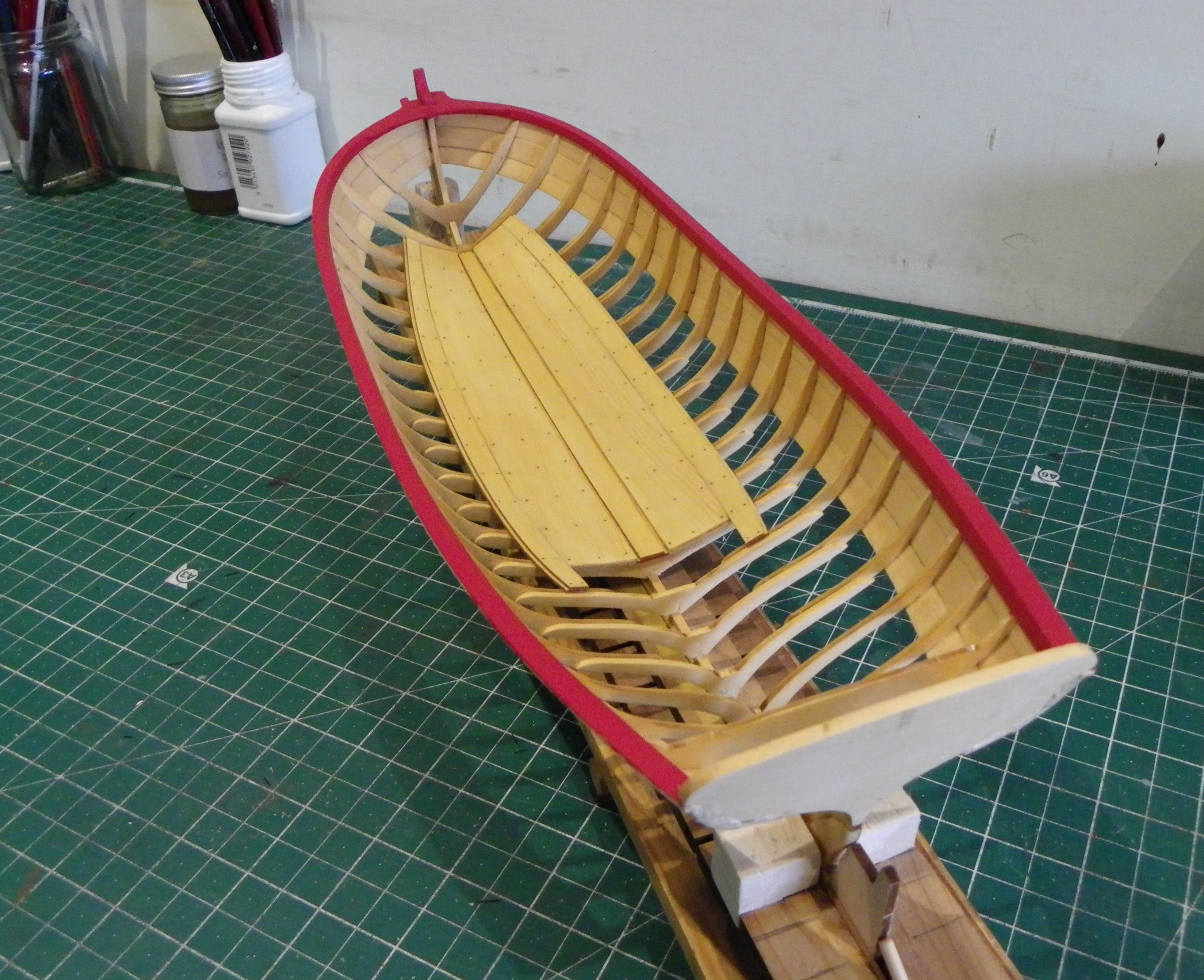
Regardless of any authenticity aspects I think the underside now looks acceptable.
Still some finishing off to do but I’ll complete the bow platform first.
B.E.
12/07/2024