
.JPG.ca33079f5815b861e67b9c2cccd37982.JPG)

Blue Ensign
-
Posts
4,284 -
Joined
-
Last visited
Content Type
Profiles
Forums
Gallery
Events
Posts posted by Blue Ensign
-
-
-
-
-
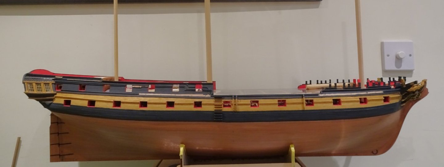
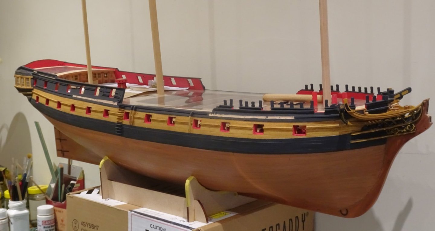
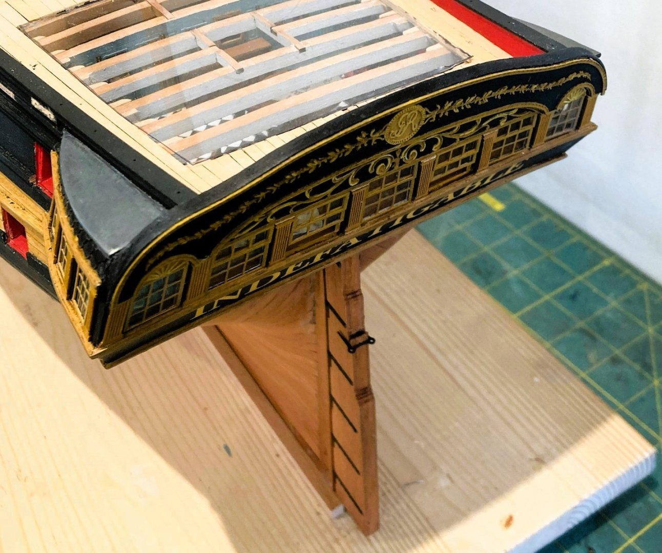
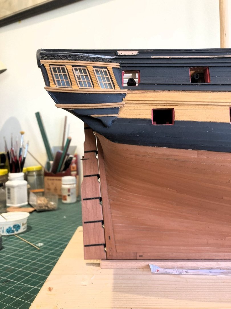
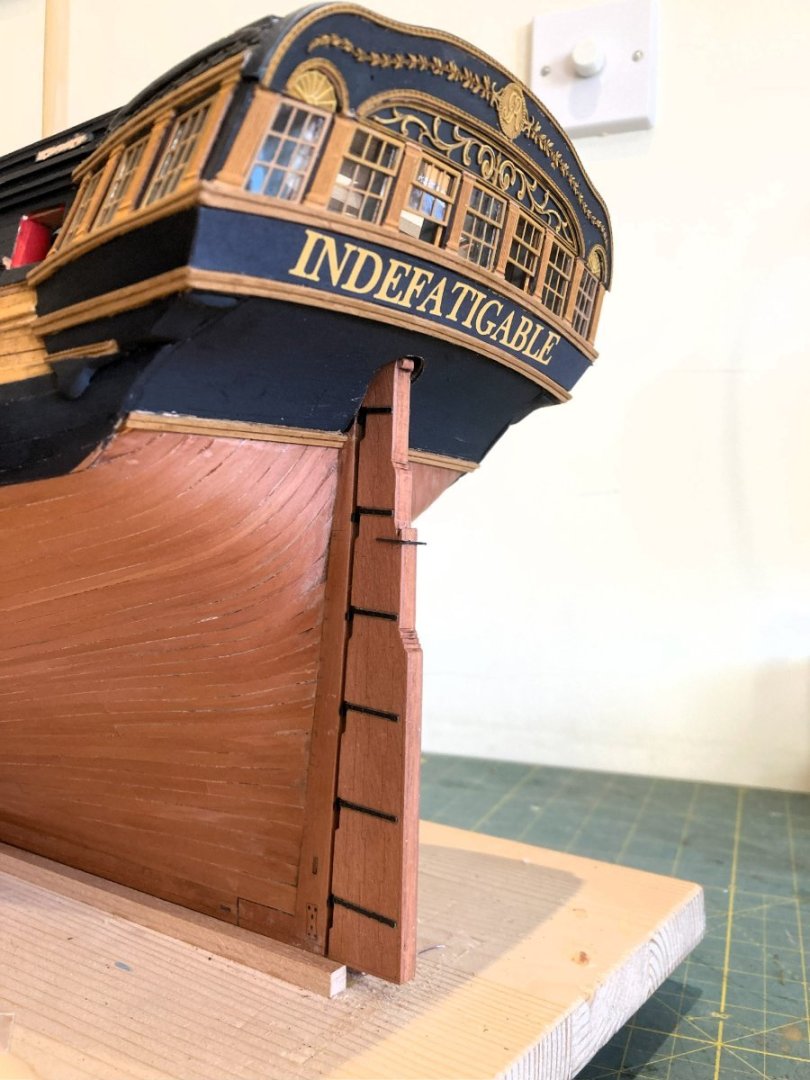
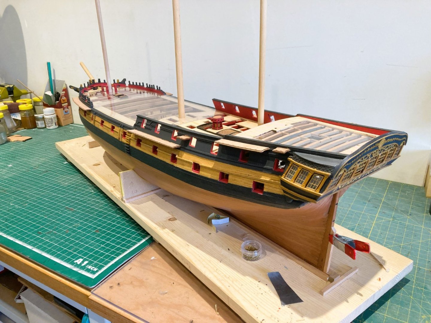
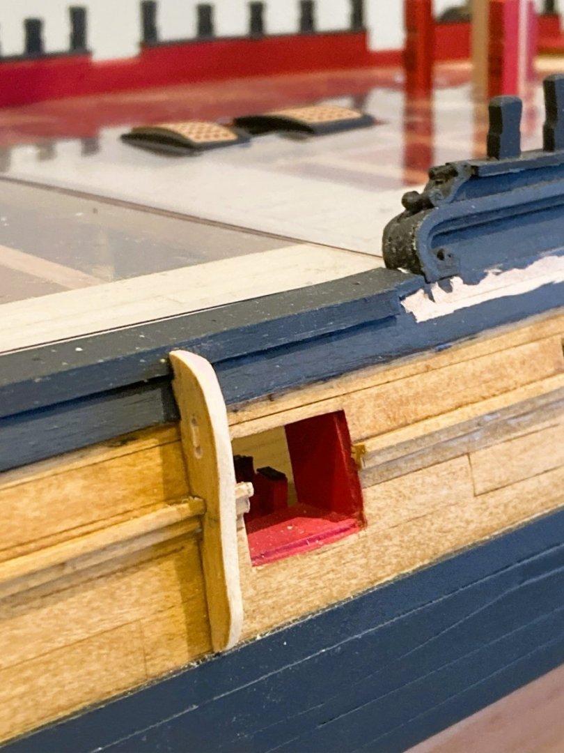
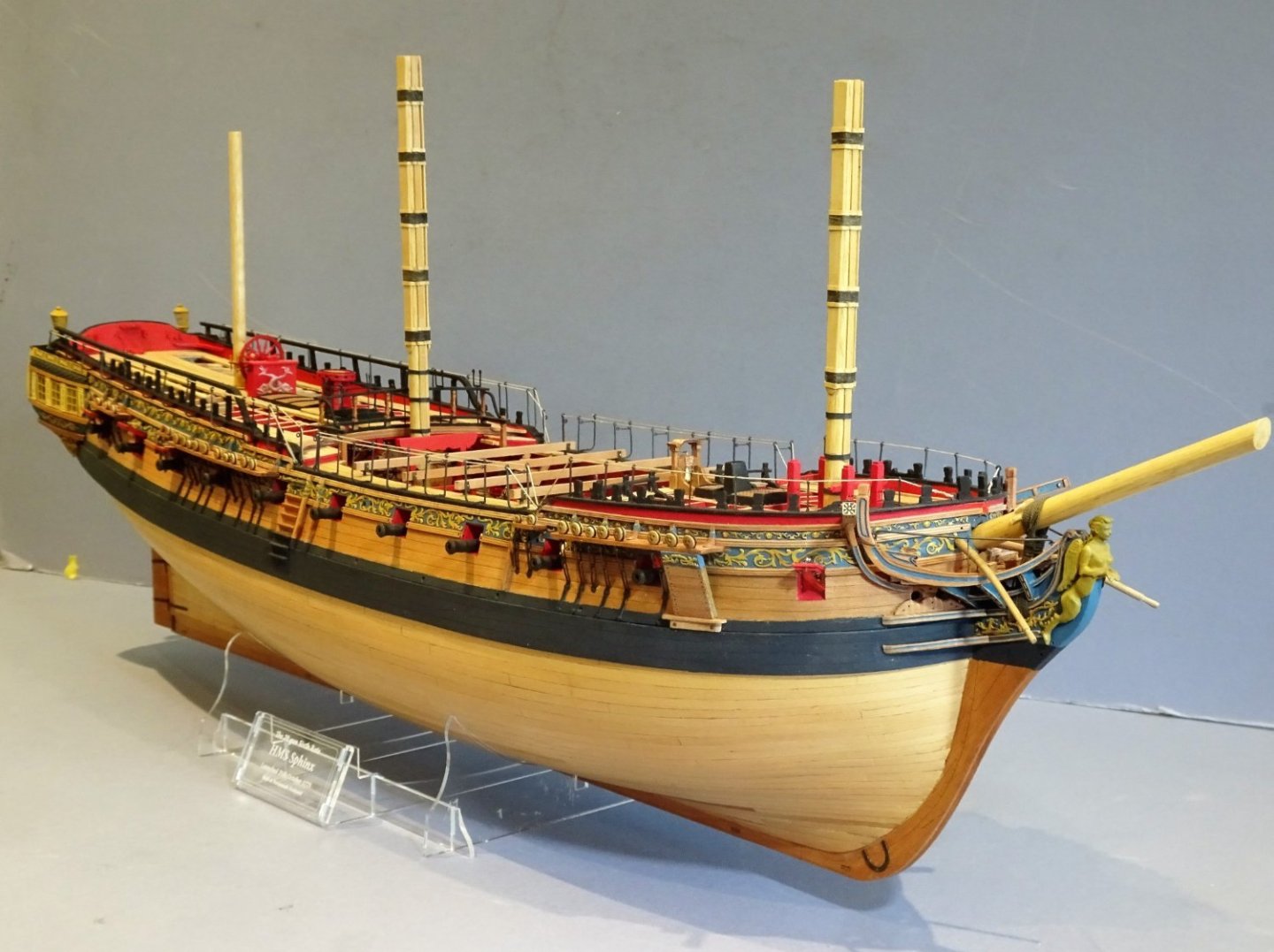
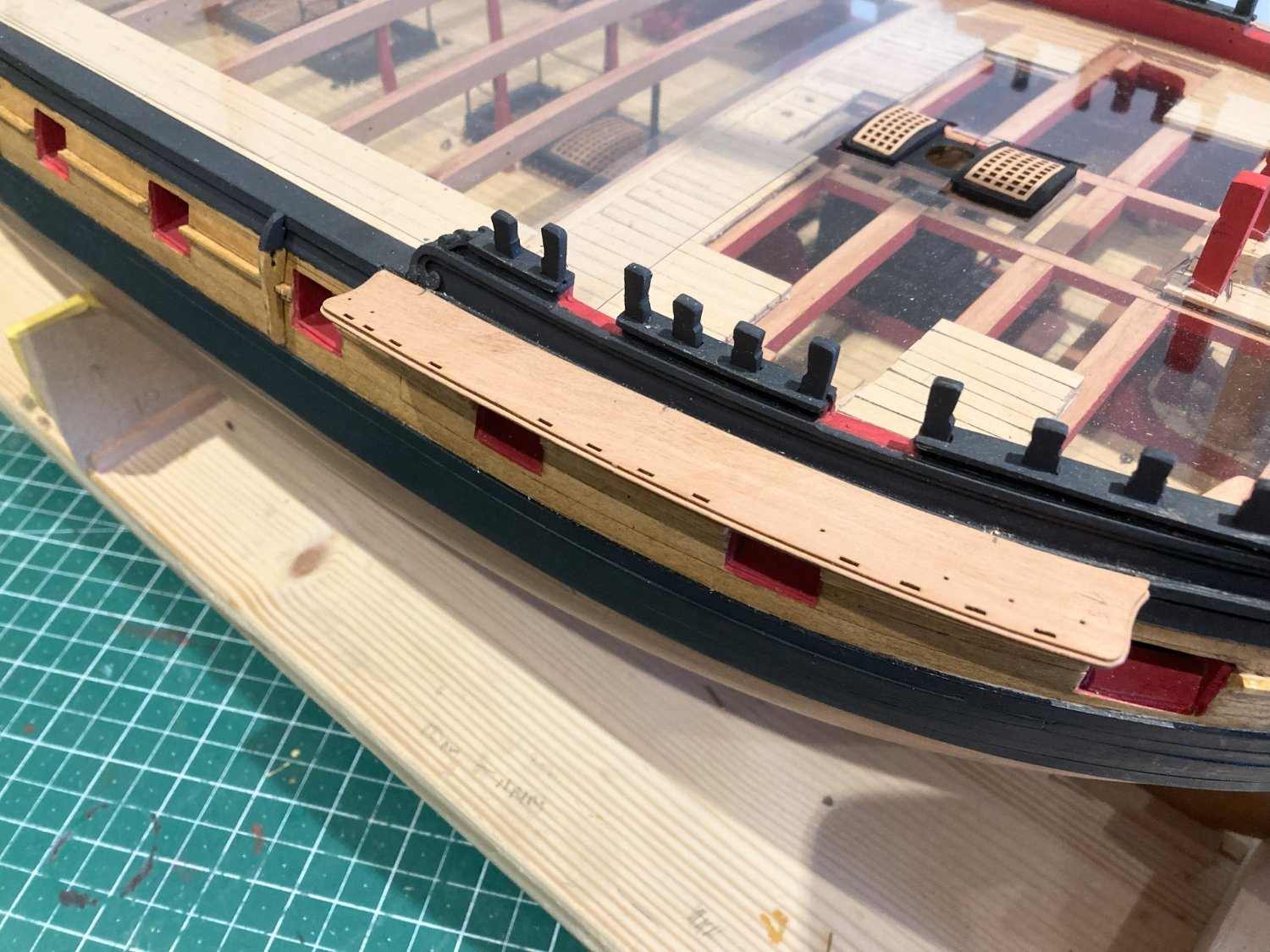
Post One Hundred and Twenty-nine
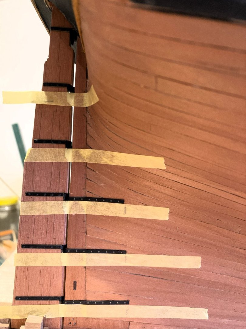
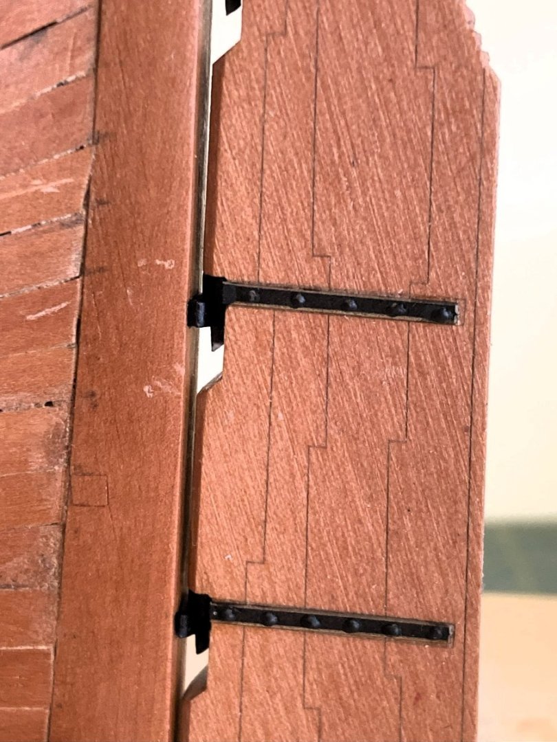
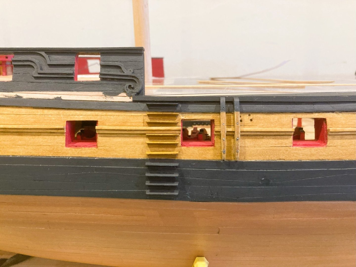
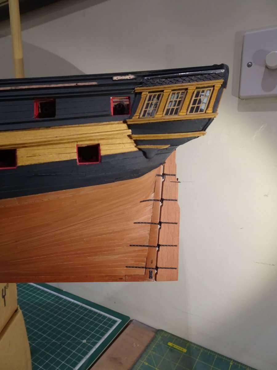
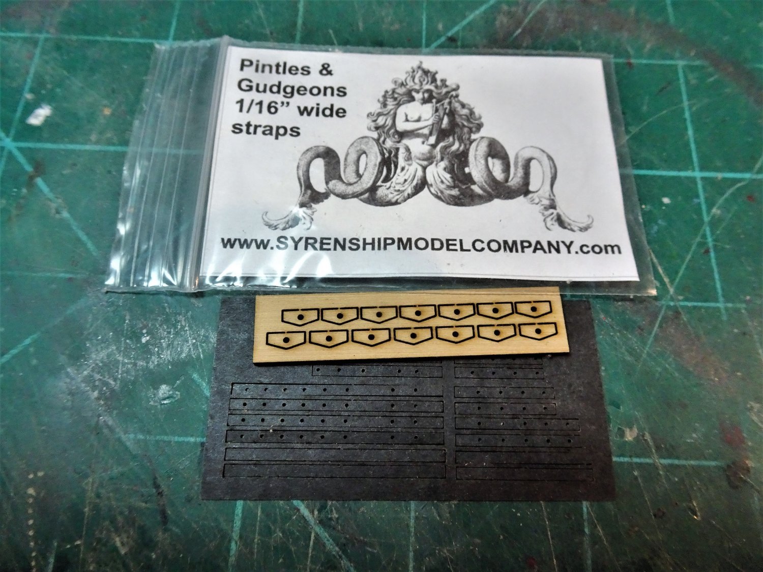
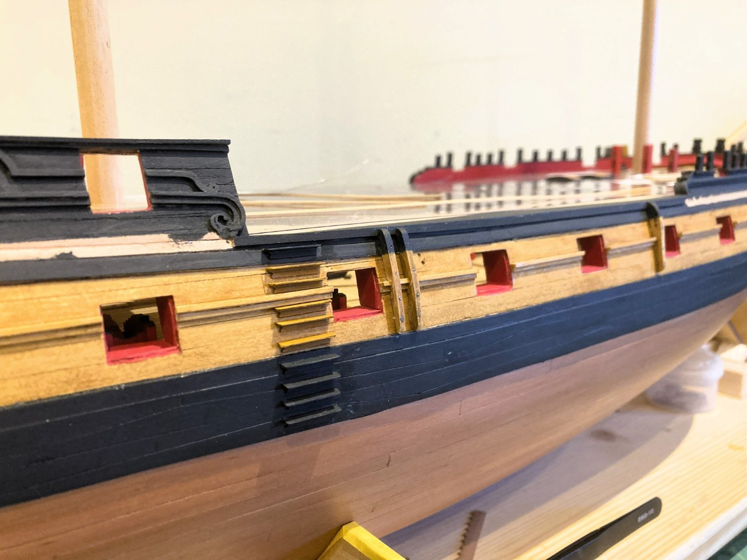
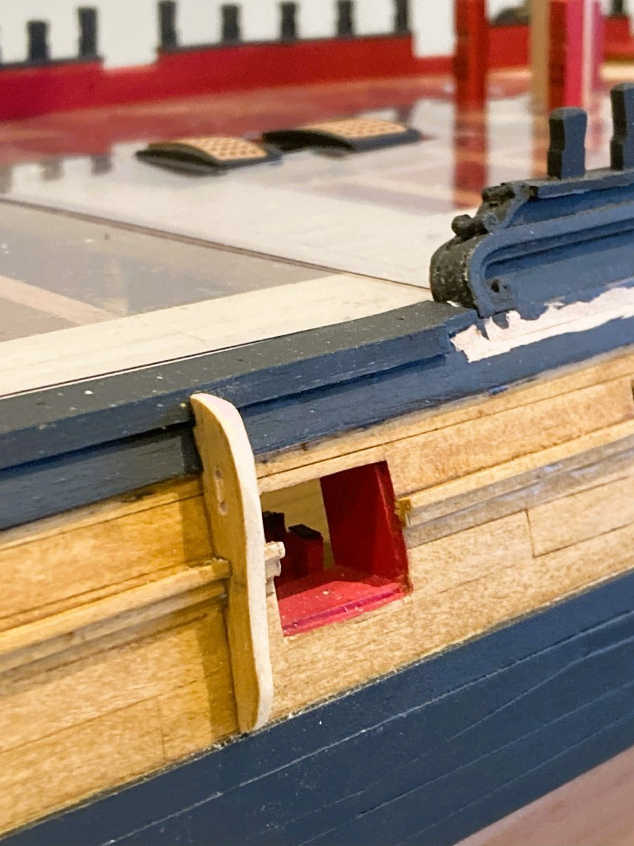
Gudgeons
With the rudder in place the line of the straps can be marked.
1782A
The straps are easily lined up on the hull to butt against the Gudgeon centres.
Trickier to fit than the rudder straps and care must be taken to avoid ca spread. The tape helps a little with this.

3216

3217
The Laser Board straps adhere well to the hull.

1787A
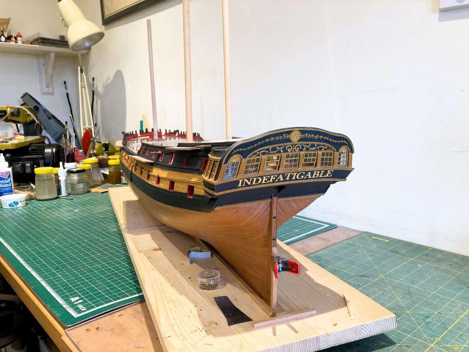
A touch-in of black paint on the stern post edges finishes the effect which should be the look of complete iron brackets attached to the hull.
Has the design achieved this; in my view it has.

3221
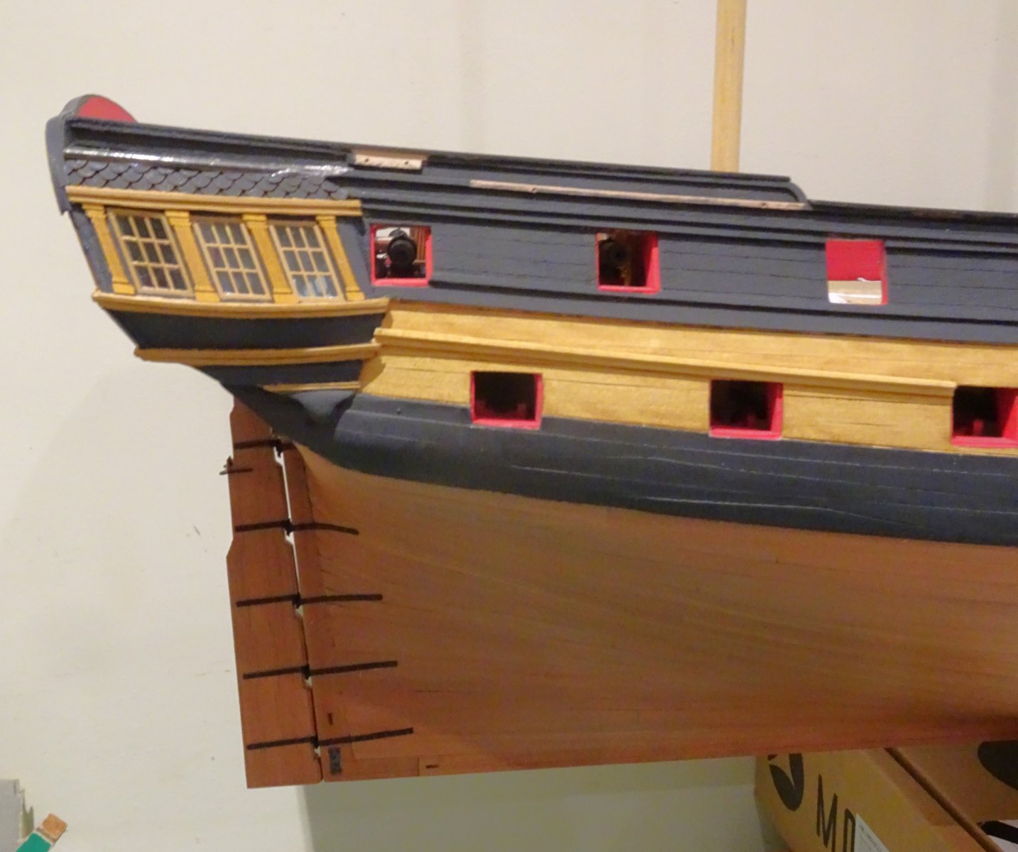
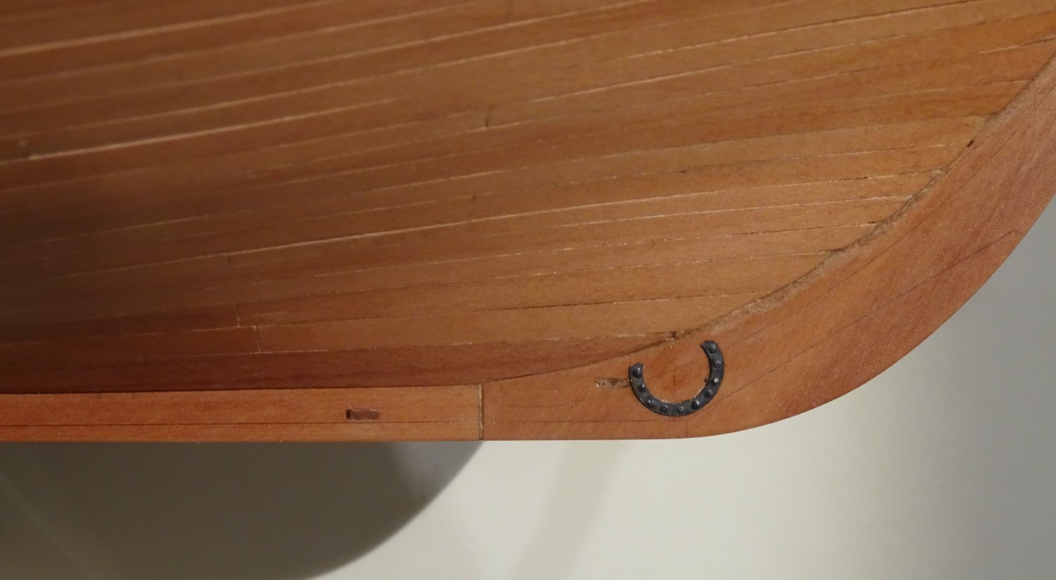
This is also a convenient time to apply the Horseshoe and Fish plates to the lower hull.

3227
These are brass etch versions, but they are another item suitable for Laser Board production.
3219
3222
A carronade assembly session looms, what joy.🙄
B.E.
10/01/2024
-
-
Post One Hundred and Twenty-eight
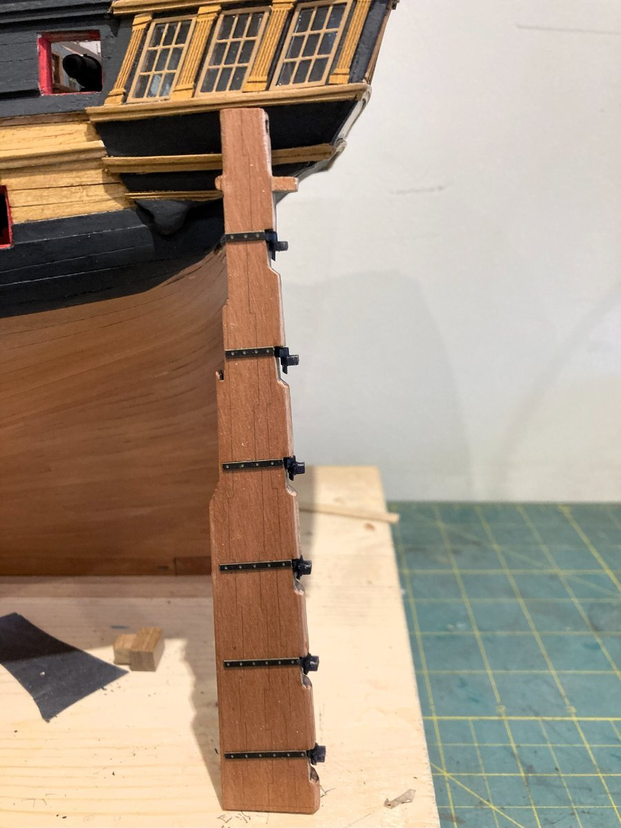
Shipping the rudder
I thought I would add the rudder now as fitting involves positioning the hull for access.
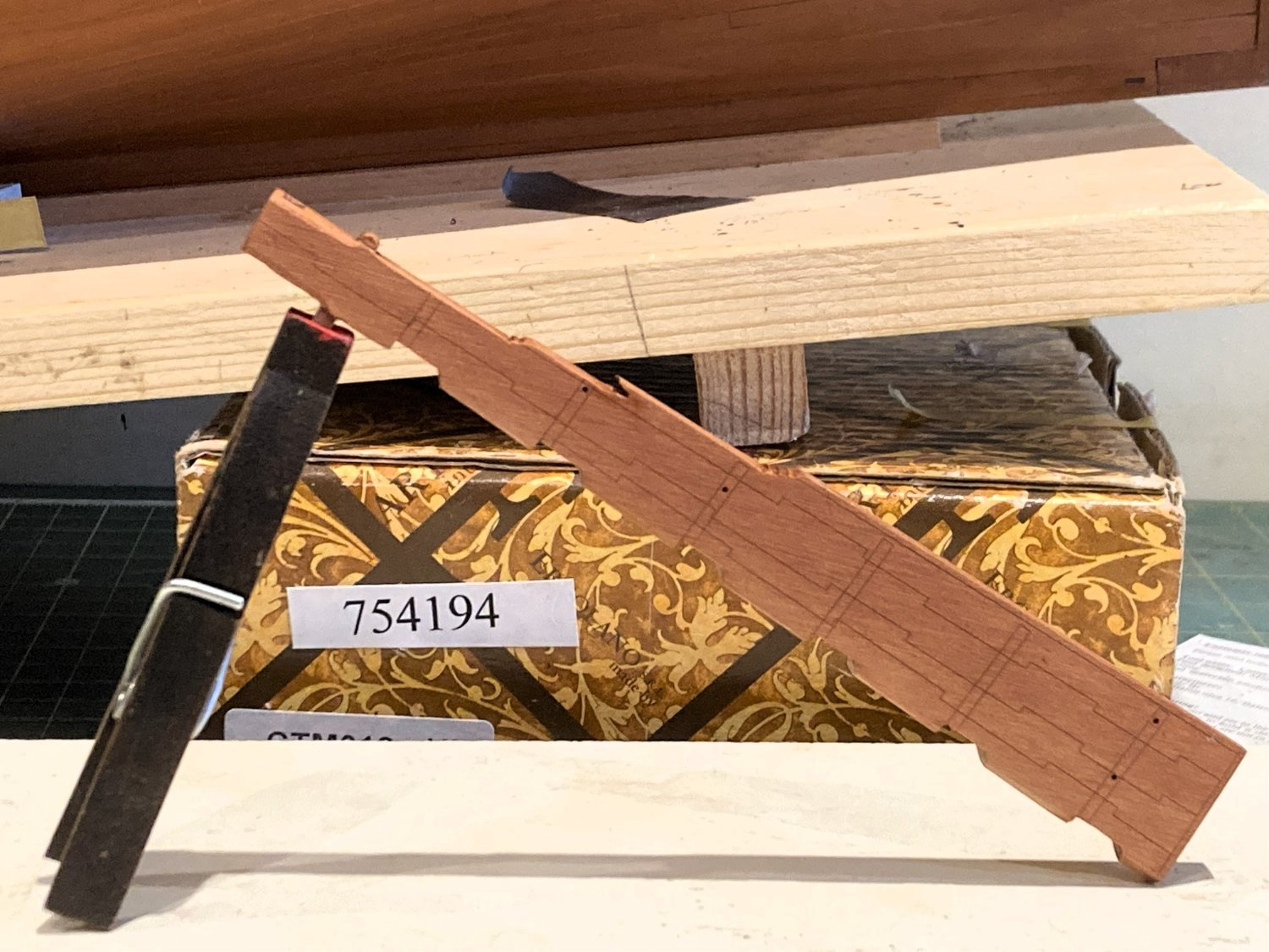
The rudder has a central Pear core with facings engraved to represent the tablings and other sections that properly make up the rudder of a large ship.

1754a
As I won’t be coppering, all this detail will remain visible.

3198
Before assembly of the rudder it is a good idea to check the fit thro’ the rudder port and against the stern post.
I found I needed to fettle the port a little to get the head of the rudder into position.

5434
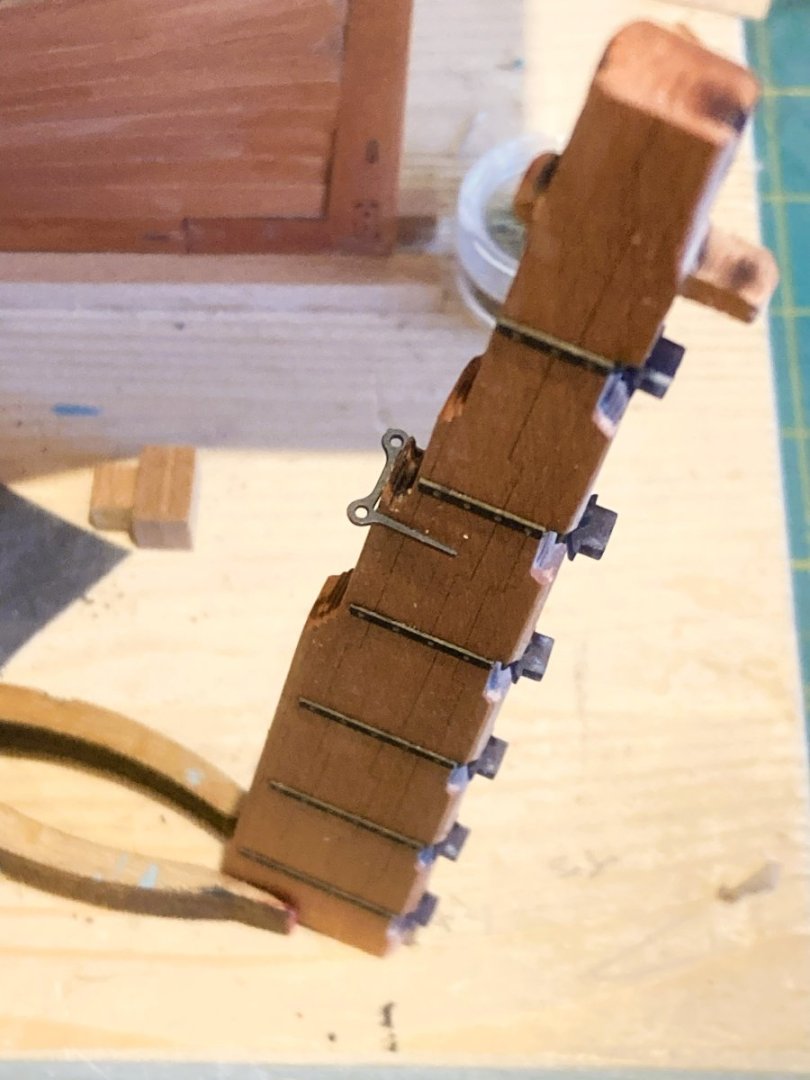
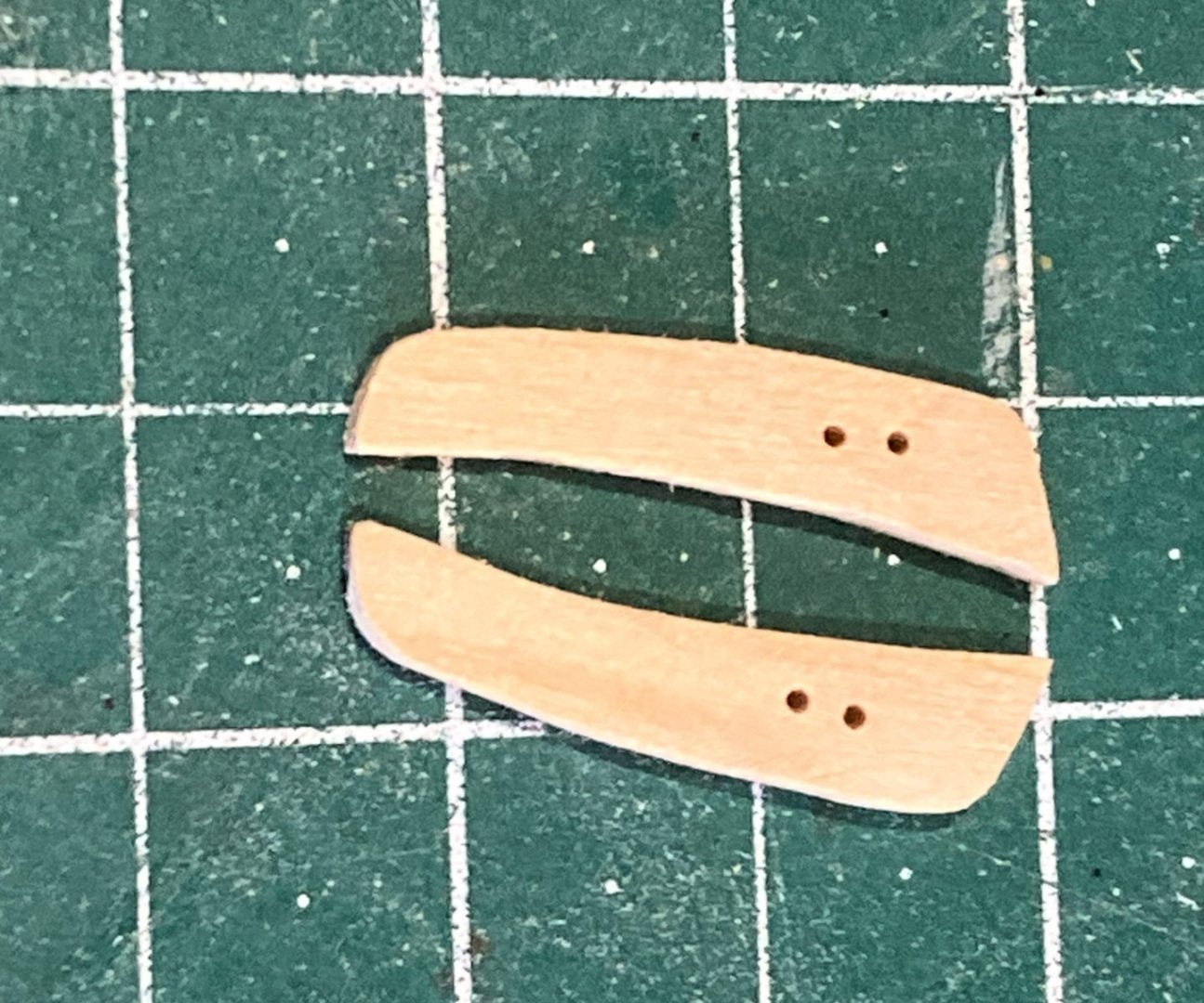
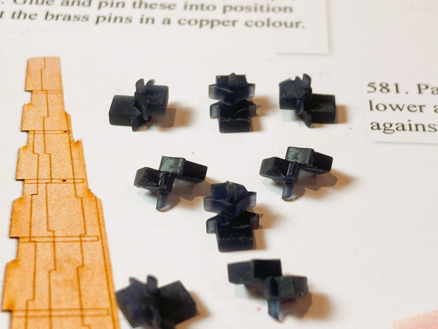
With regard to rudders I have mostly used the Syren system which produces a moving rudder on individual pintles and gudgeons.
.thumb.JPG.c32d6a34d26f3fcd9aa93b9408e7fe68.JPG)
2271(2)
On Sphinx the kit provided ‘faux’ pintles/ gudgeons (above) were a thin brass etch affair which didn’t do it for me, and I used the Syren system.
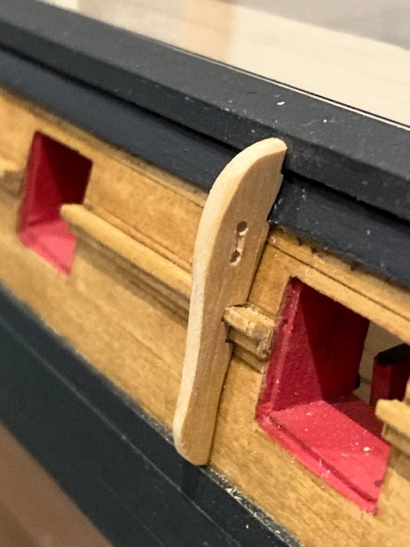
The arrangement on ‘Indy’ is a much-improved resin version of a pintle/gudgeon combo and with laser board straps replacing the brass etch.

1750a
Chris has done a fine job in replicating these items and I am sufficiently impressed to use them on my build.
These little widgets slot into the Rudder beautifully, and the corresponding gudgeons match to the slots in the stern post.

1759a
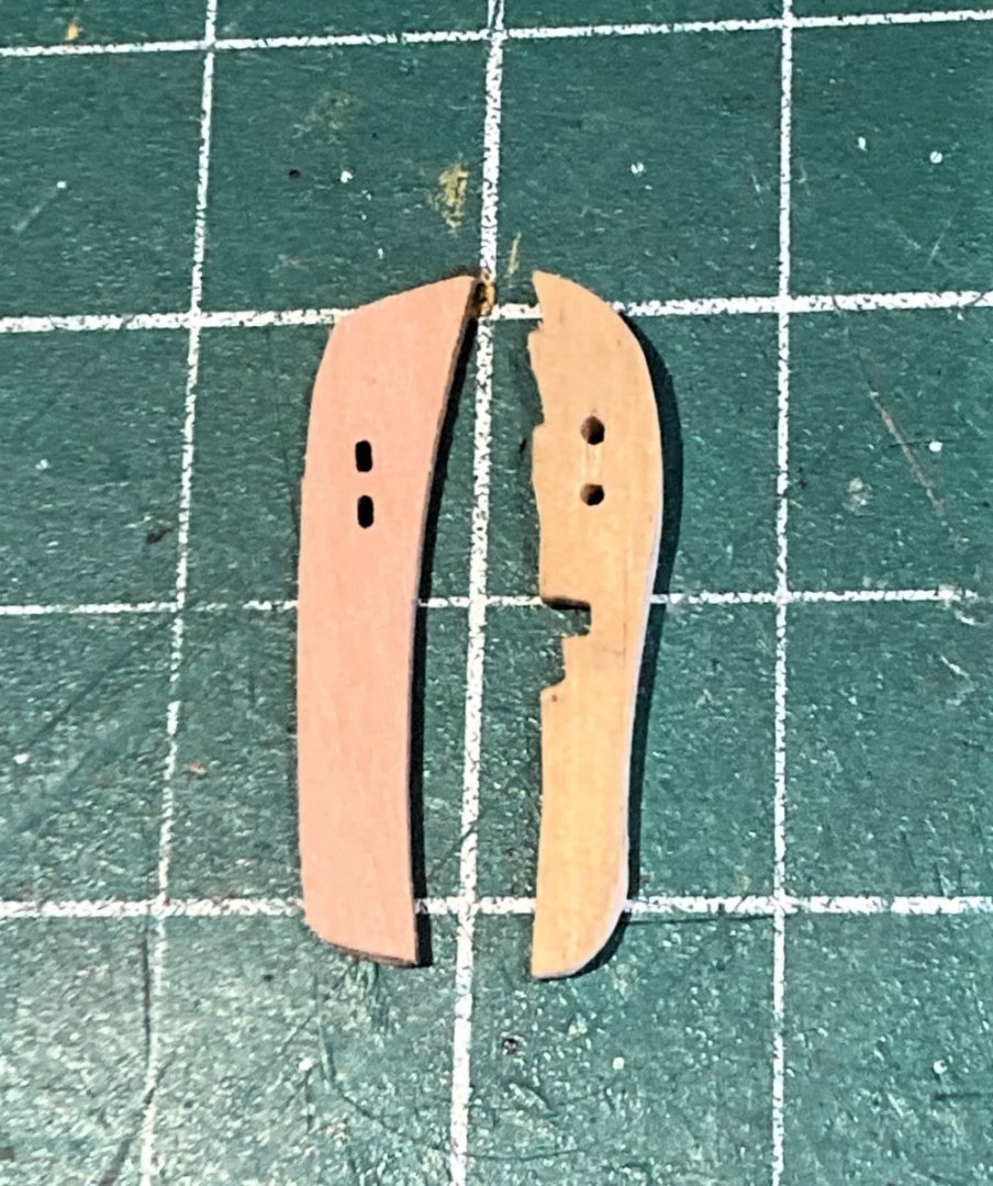
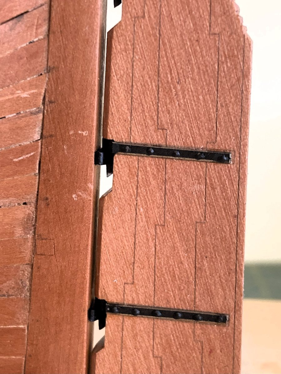
The strap positions are marked on the rudder for the pintles, for accurate fitting.
I think it is also a good move to make the straps out of laser board, saves all that brass blackening and then messing it up during fitting.
1778a
The manual indicates use of brass pins inserted into drilled holes on the straps. I prefer to represent the bolts on the straps using blobs of pva applied with a toothpick.
The final addition to the rudder is the Spectacle plate.
1763a
This is chemically blackened brass etch.
1767b
1786a
1765a
The fit of the rudder is excellent, with a good push fit.
With this system there are no worries about getting a close fit to the stern post.
Well done Chris.👍
B.E.
09/01/2024
- fake johnbull, CODY, ccoyle and 24 others
-
 27
27
-
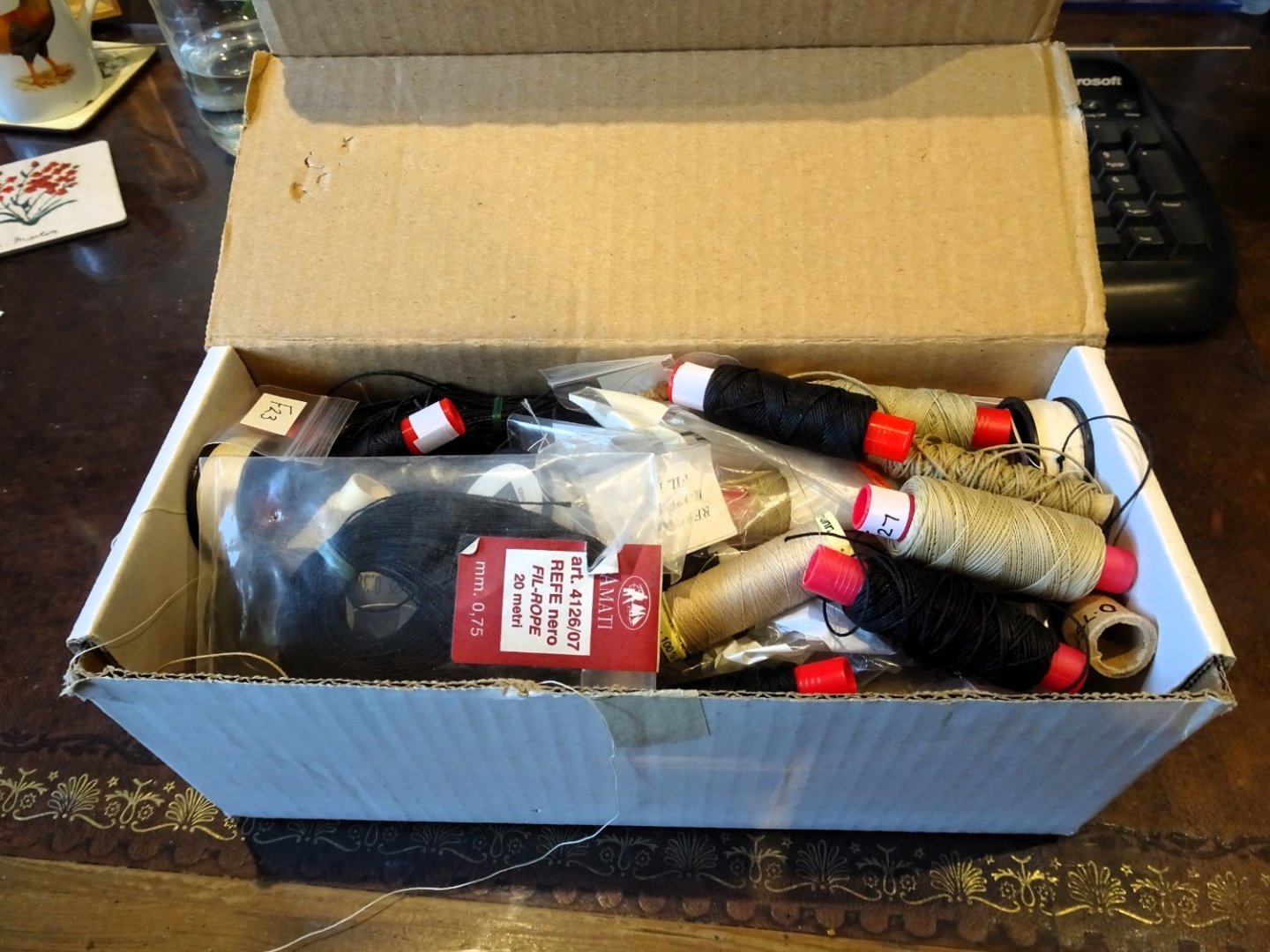
Mine just builds up, I could open a shop selling Amati and other kit line.
3205
I never use black thread in my builds, and kit provided thread rarely if ever provides sufficient sizes for proper scale rigging.
These days I only use Syren, and Morope for very fine lines, useful for seizings.
B.E.
- Ryland Craze, Keith Black, AJohnson and 1 other
-
4
-
-
Post One Hundred and Twenty-seven
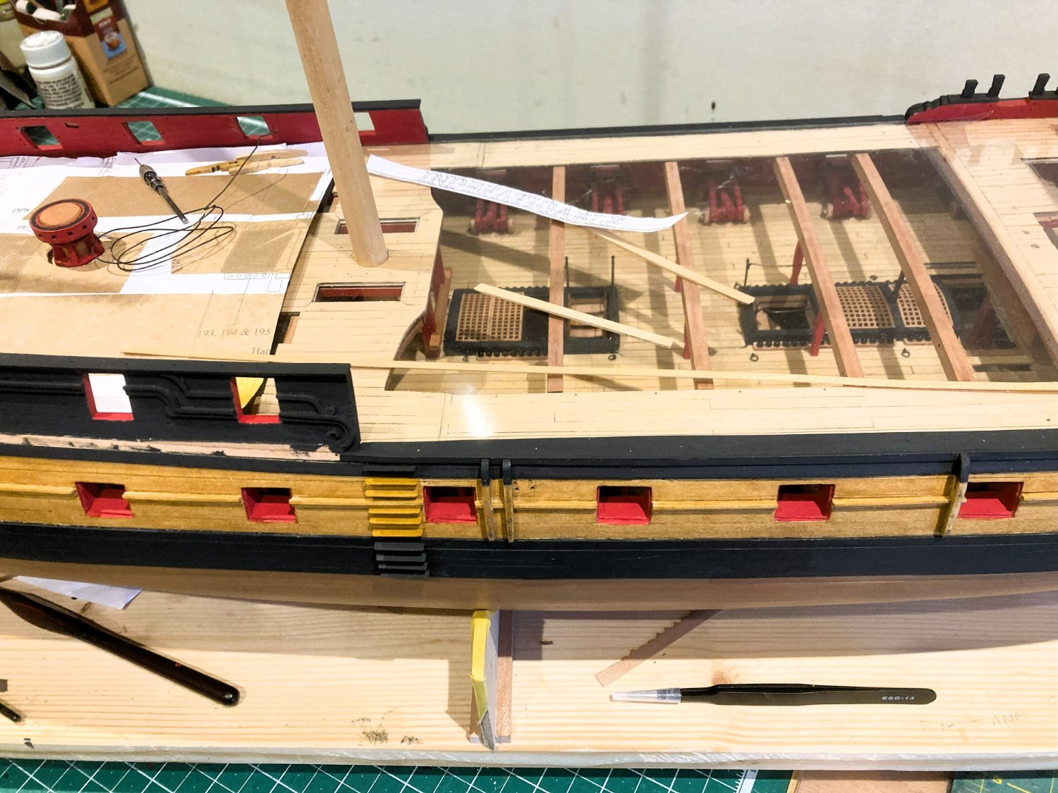
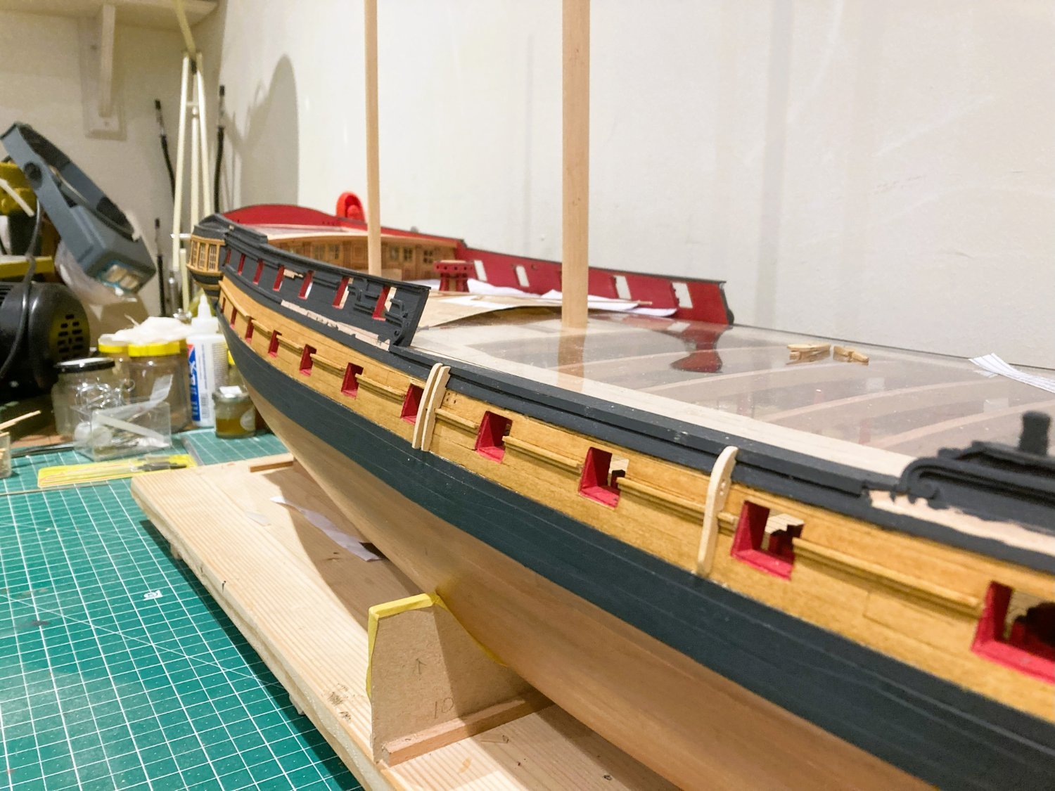
Channels
The channels each comprise laminations of three parts. The core centre part is rounded on the edges and extends slightly beyond the upper and lower pieces to create a decorative profile.

1748a
In practice the edges of the channels were open to receive the deadeye strops, and a cover strip was nailed over the top, decorative or otherwise.
Quite a straightforward business prepping the channels; largely making sure you have the correct cores and matching outer pieces, carefully applied to each side of the core, and aligned with the slots and holes.

1740a
The Main channels require more bevelling on the aft side to account for the greater tumblehome.

1739a
The Fore channels require bevelling and a little fettlin’ to match the round of the bow and take a little more time to fit.
3192
The Mizen and stools for the main and Mizen backstays require little attention and there are location holes in the hull for accurate fitting.

3194
3189
A well-designed set-up by Chris for what can otherwise be a tricky exercise.
1733a
Whilst in the area of the Poop I added a lead sheathing to the Gallery roof, this will tone down to a dull grey over time.
1731a

1744a

1745a
Before I permanently fix the channels I think I will return to the deck and inner bulwark fittings.
At this point the channels will just present another incumbrance to be careful about when working inboard.
B.E.
07/01/2024
- Craigie65, scrubbyj427, AJohnson and 24 others
-
27
-
You are right Chris,
As a builder of the 1/64 scale Vanguard' Indy' I can attest that it is a large and heavy model on its building board, and at times moving it around to work on can get quite wearing. Fully rigged, this model will require a significant display area, and I don't think I could accommodate a 1:48 scale version.
The link on my original post to 'The art of age of sail' shows the scale as 1:64?
B.E.
-
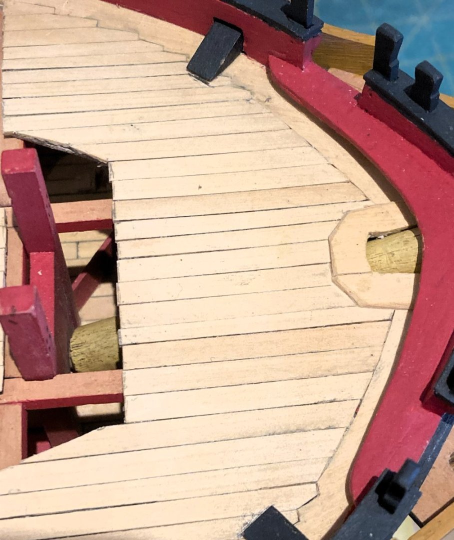
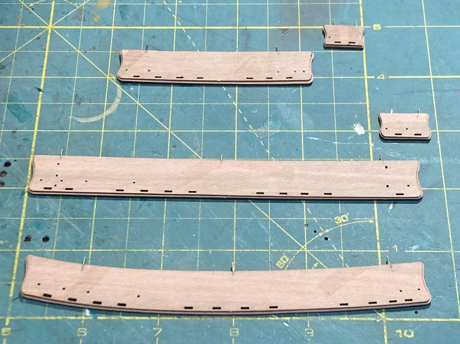
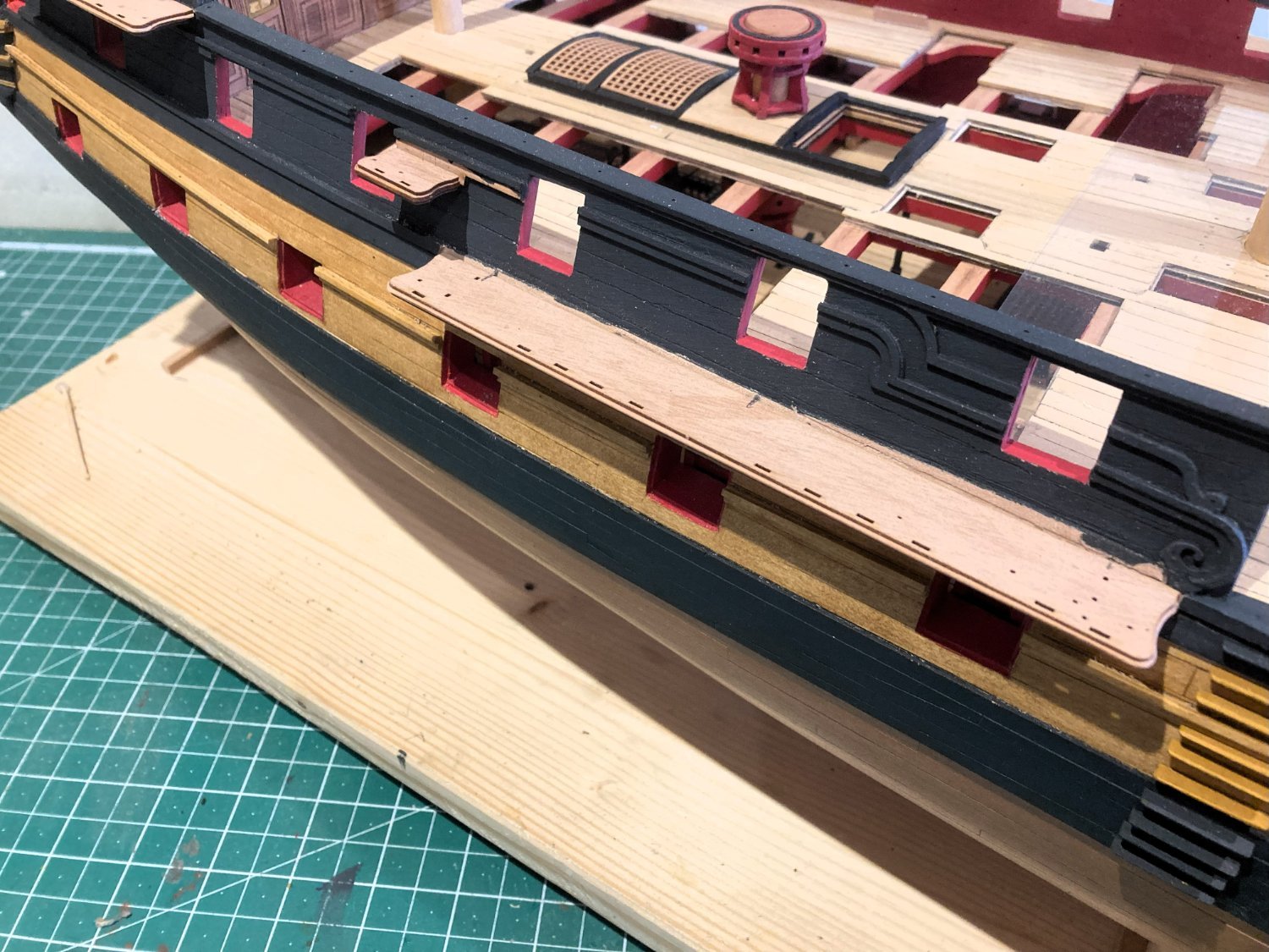
Post One Hundred and Twenty-six
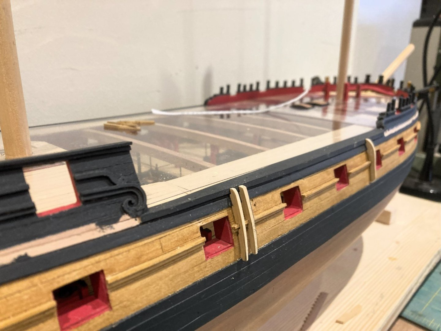
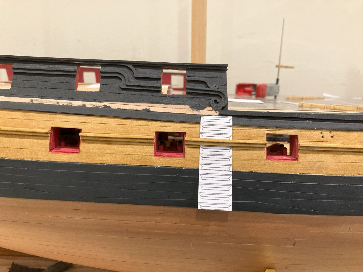
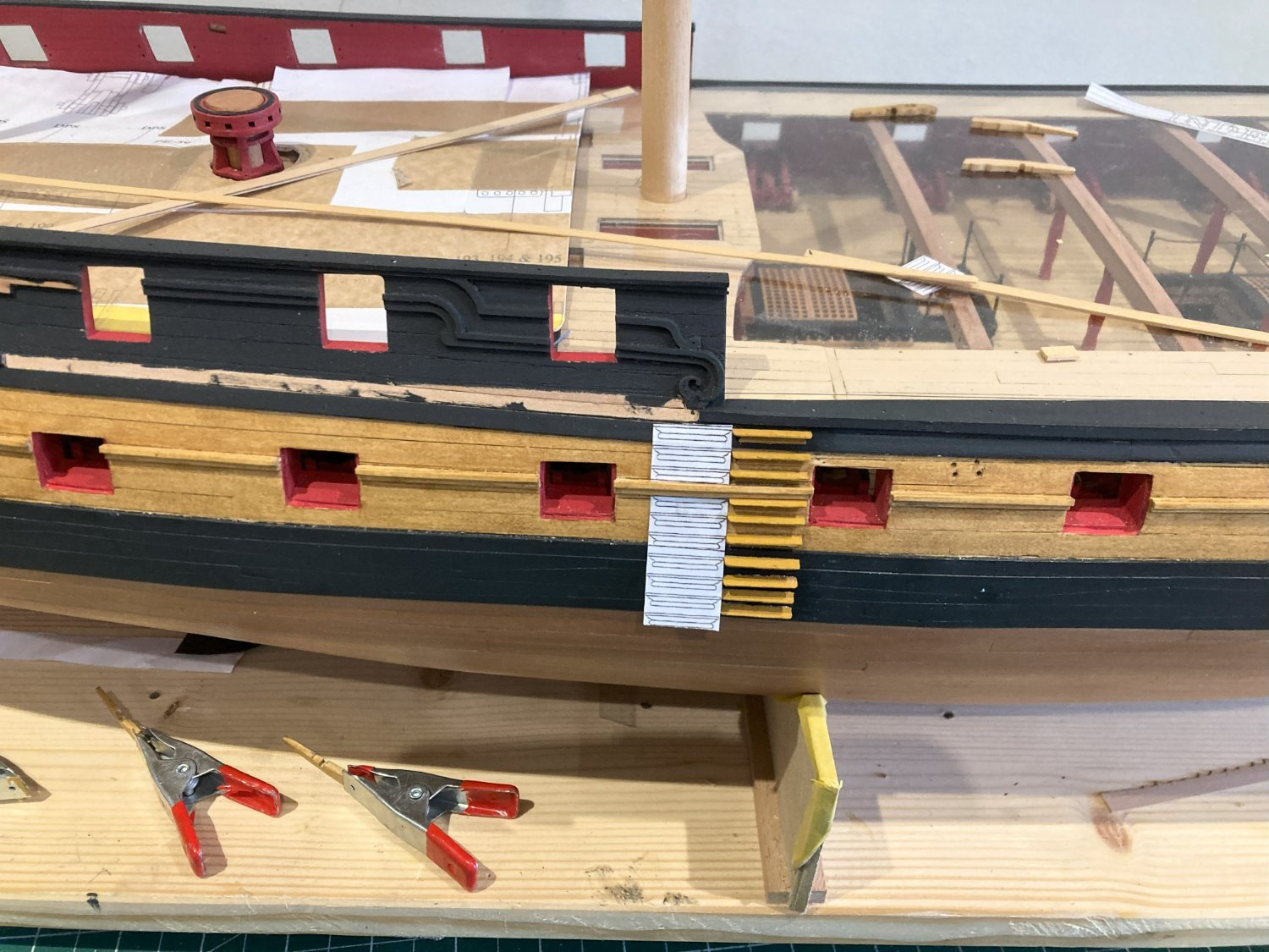
Side Steps
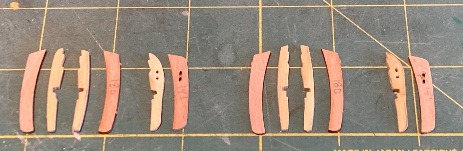
There are ten of these fiddly little items to assemble for each side.
The step equates to a depth of around 7” and length of 2’ 4” which seems about right.
One of the trickiest things with steps is attaching them to the hull with correct spacing and alignment.

1711a
To assist with this a copy is taken from the plan and attached to the hull adjacent to the actual line. This provides a guide for both position and level.

1712a
Pva is used to attach the steps.

1723a

1725a
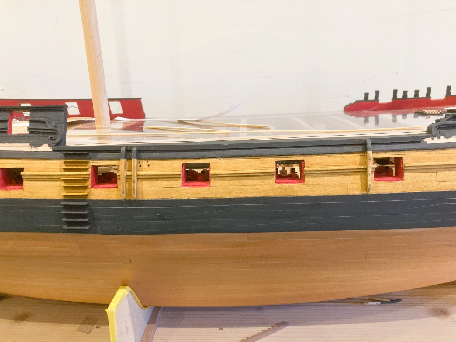
The fenders and Chesstrees are fixed into position, they took me a fair amount of fettlin’ to get them to sit right against the hull.

1726a
I wonder if it might have been a better option to cut the moulding rather than notch the fenders.
1722a
Once fitted I drilled and ‘bolted’ the items to the hull. These were items subject to wear and tear and needed to be replaced fairly easily.
B.E.
04/01/2024
- Kevin, mgatrost, DonSangria and 23 others
-
26
-
-
Post One Hundred and Twenty-five
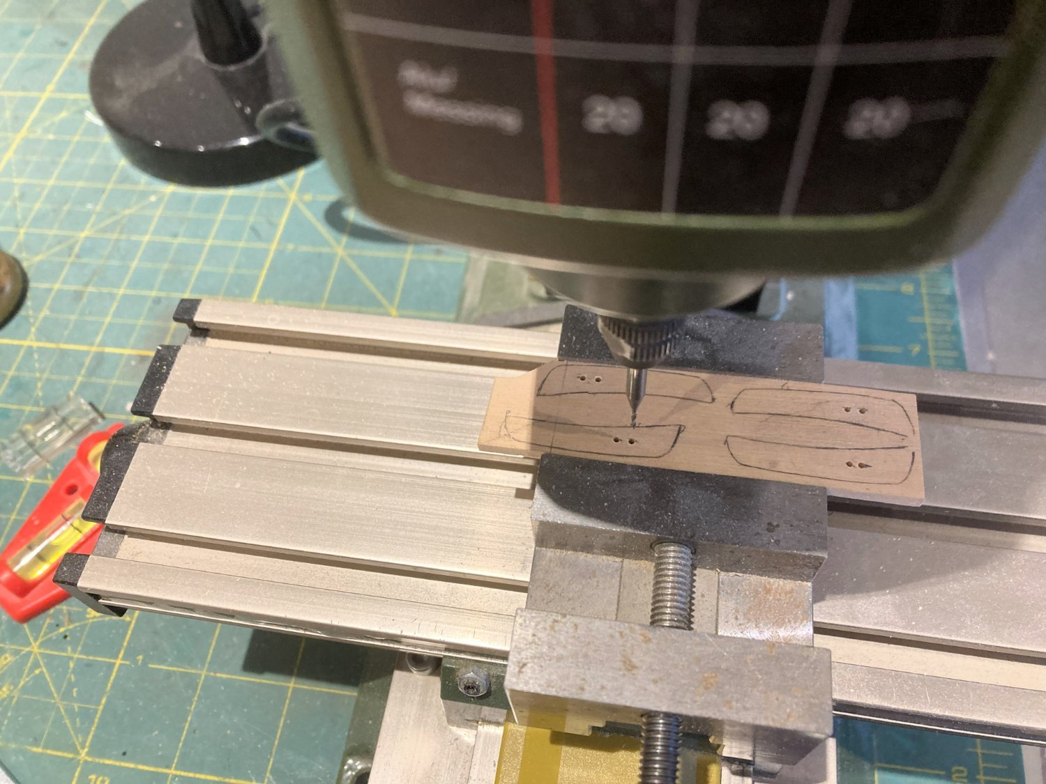
Looking at Chesstrees and Fenders.
The kit provides a basic shape for the fenders and Chesstrees but they both stand a degree of enhancement to achieve a more authentic look.
They are made of uniform 1.5mm laser cut pear which is about right for the bottom end at the wale but ideally should be slightly broader at the top, around 2.5mm.
Using dimensions from the Adm. plan I cut replacements out of some Boxwood scrap.

1687a
The sheaves were marked and drilled out on the little miller, and the shape cut out on the scroll saw.
1688a

1689a
At this stage the same pattern as the kit items but with a taper applied.
1699a
Together with a taper, a more elegant serpentine shape is better representative of how these things should look.
1694a
1695a
Testing for fit.
Altho’ I have used Boxwood to match my hull timbers, the kit parts could be laminated to allow for a taper, and a little more shaping to be applied.
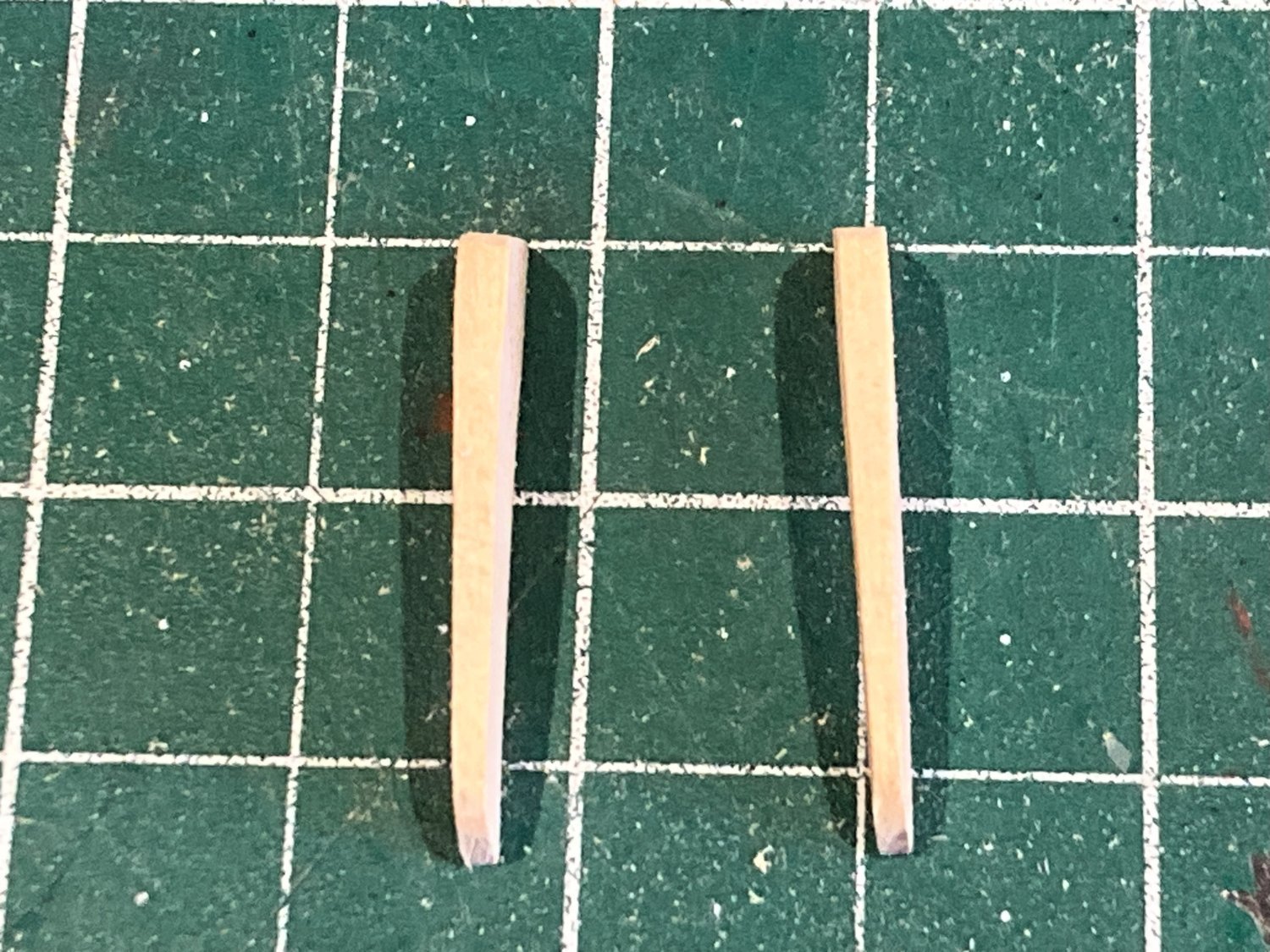
The same approach was taken with the fenders.
Even on completion I thought that the depth of the fenders looked too much, almost out of scale for the hull.
I looked at many photos of fenders and chesstrees on models contemporary, and modern, and they all seemed finer than the
kit offering.

1707a
I didn’t have any exact dimensions to work from but I fined down the pieces until they satisfied my eye.
1704a

1705a
This is the result.
Getting there but I still think I can go a tad further.
The convex shape of the fenders initially looks odd given that on purpose built single deckers they are more concave in shape with a slight serpentine effect, due to the tumblehome.
On ‘Indy’ the tumblehome element of the waist has been cut away leaving just the lower hull round for the fenders to follow.
Before completing the fenders I will make the side-steps.
B.E.
02/01/2024
-
That's the trouble with canine assistants, my spaniel considers anything that hits the floor is his. I have to take great care, particularly with stuff that may harm him. I was once missing a needle; that cost me £200 for x-rays, and I then found the needle on the kitchen floor, well away from my workshop.
I'm sure you will get around this Chris, an interesting build you have chosen, and I look forward to seeing progress.
B.E.
- DocRob, Knocklouder, Canute and 8 others
-
11
-
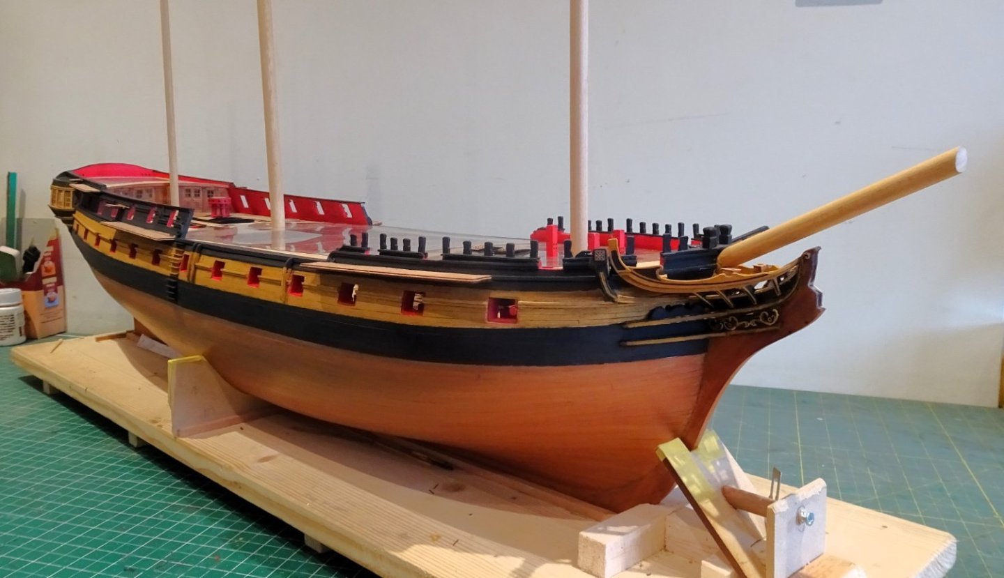
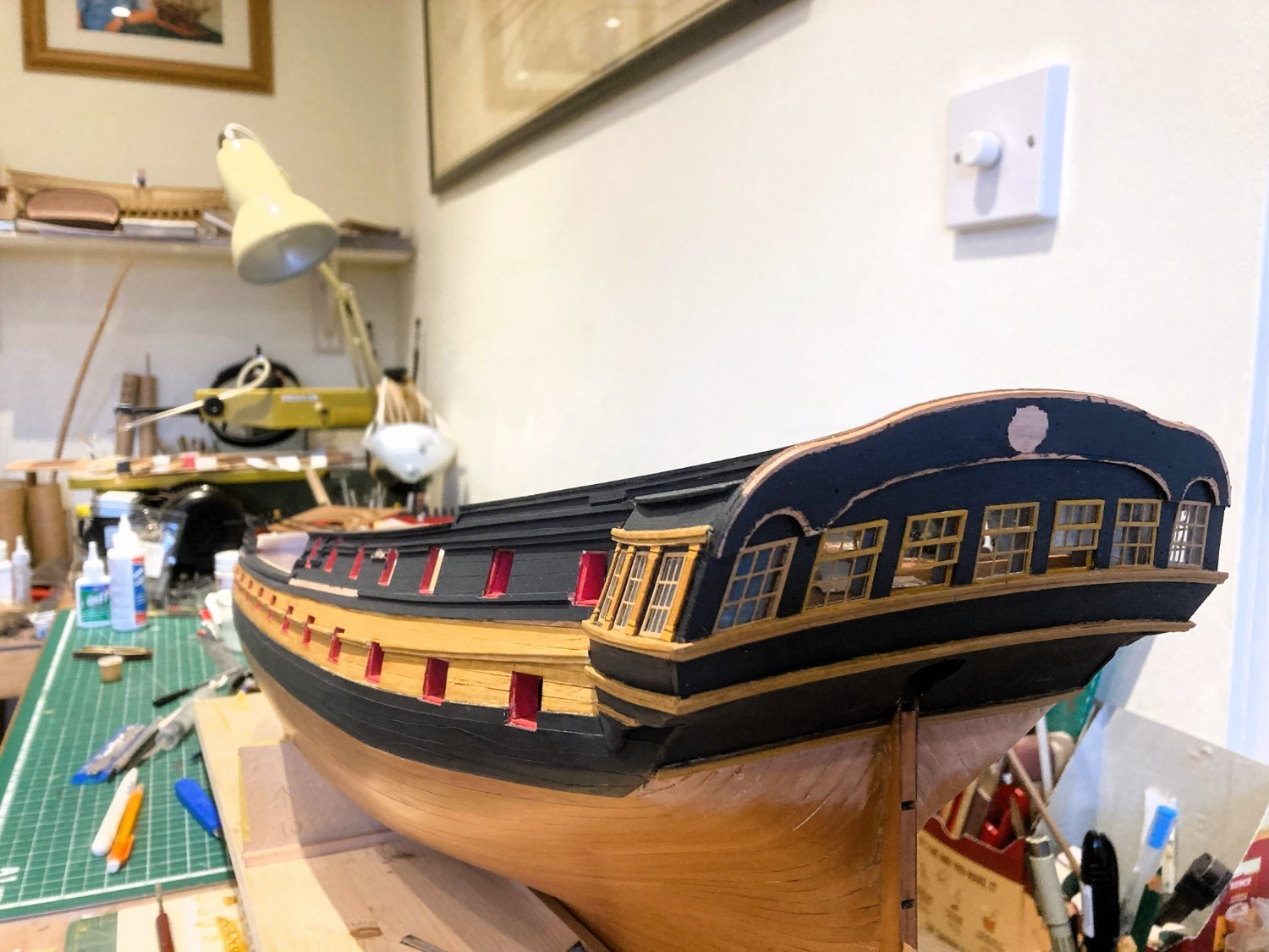
Post One Hundred and Twenty-four
Back to the Bow
… and several things to attend to.
Areas of paintwork that I needed to tidy up particularly around the mouldings.
This is a tiresome task with touch-ins on touch ins, ad nauseum.
1684a
The Decoration is added to the Trail boards
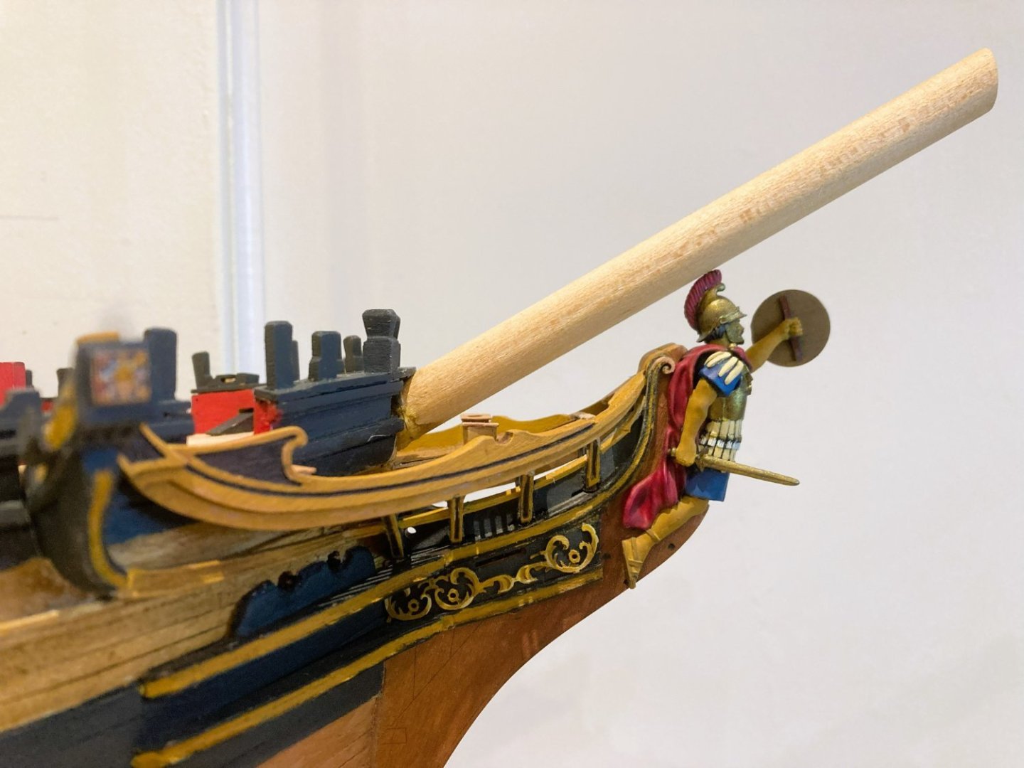
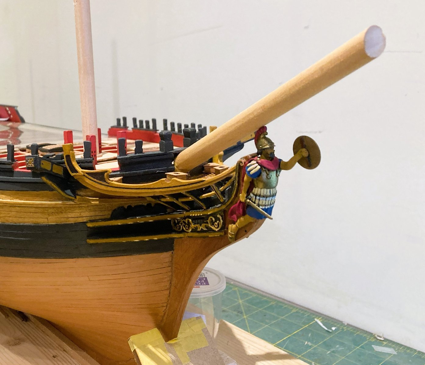
Fit of the Figure/ Bowsprit.
Left naturally the stive of the Bowsprit was insufficient to clear the top of the figure.
Whether this is specific to my build due to moving the Bowsprit stop aft to its proper position between the foc’sle bitts, I don’t know, but we are where we are.
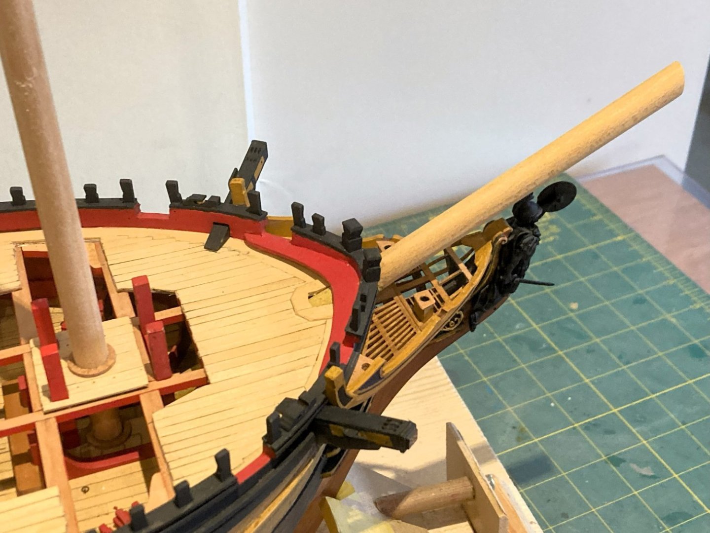
1667a

1673b
I didn’t wish to change the figure so a little inventive jiggery pokery was required on the Bowsprit.
1654a
The heel of the Bowsprit is visible below the Foc’sle deck, and the aim is to fool the eye of the observer.
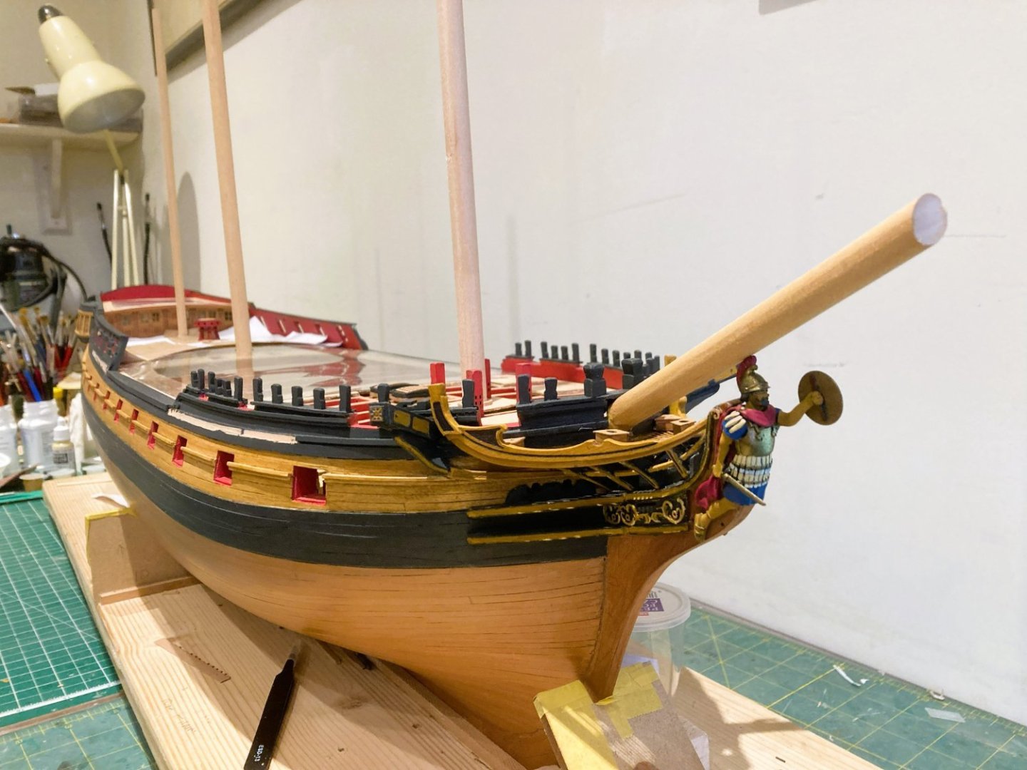
1673a
I intend to fit stump masts; for these I use Ramin my favourite dowel type. Light in colour, it provides an excellent match to Boxwood and other light wood types.
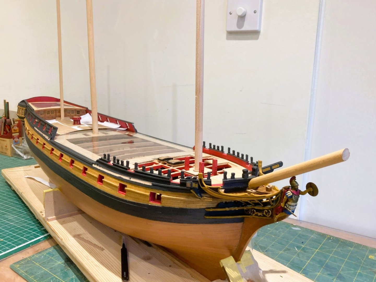
1685a
My only use for Walnut is for yards where the colouring is black. I’ve probably got several lifetimes worth of walnut dowel in my wood stock.
8778
Not that I have an interest in yards on this build, but the stump masts will be kitted out with those fittings applicable, as shown here on my Sphinx build.
B.E.
30/12/2023
-
-
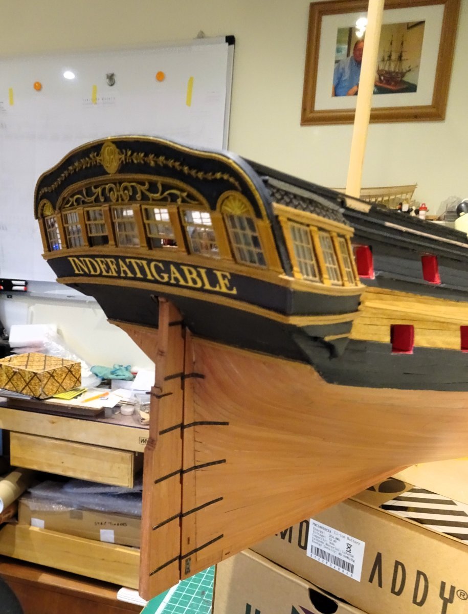
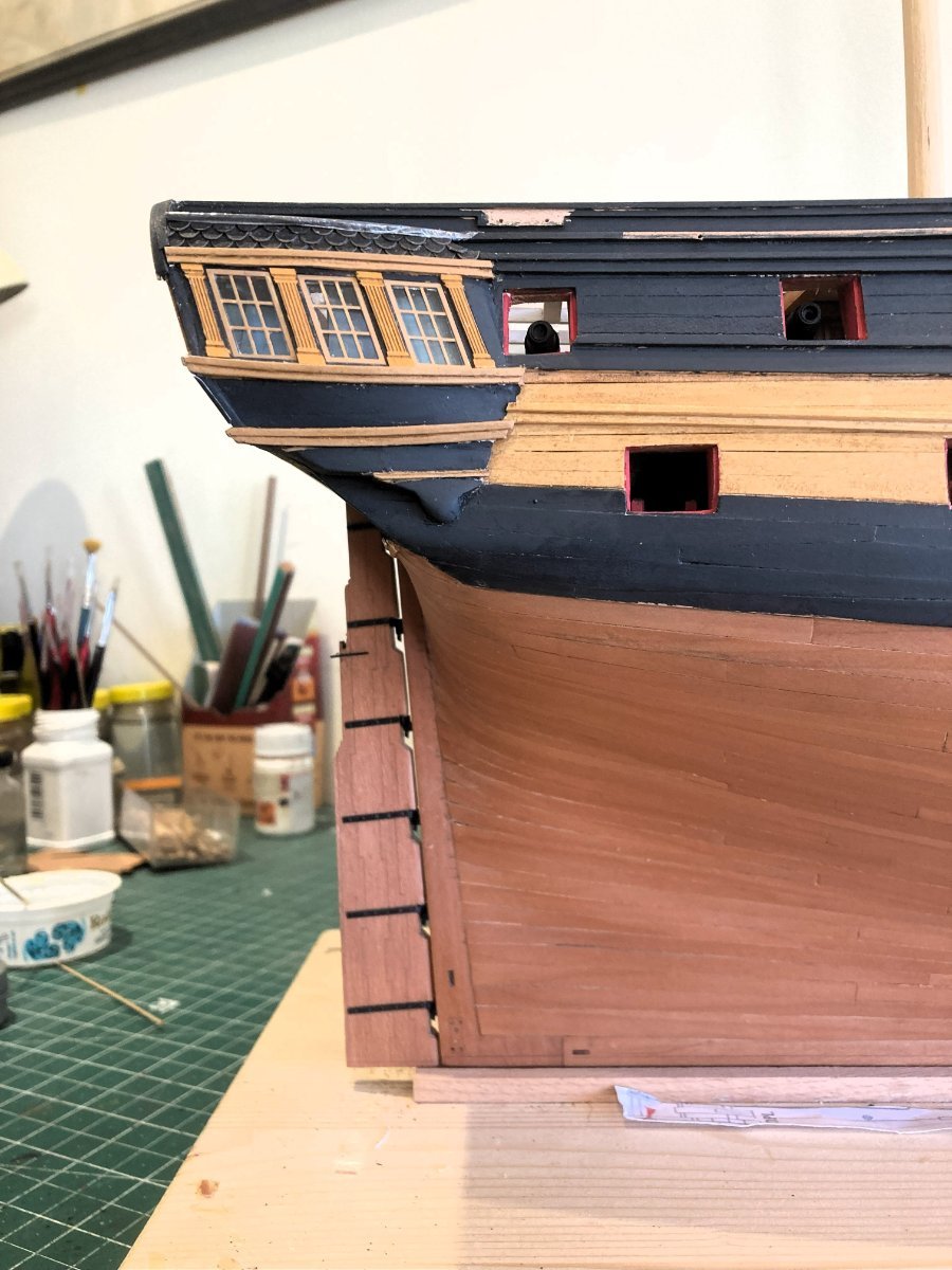
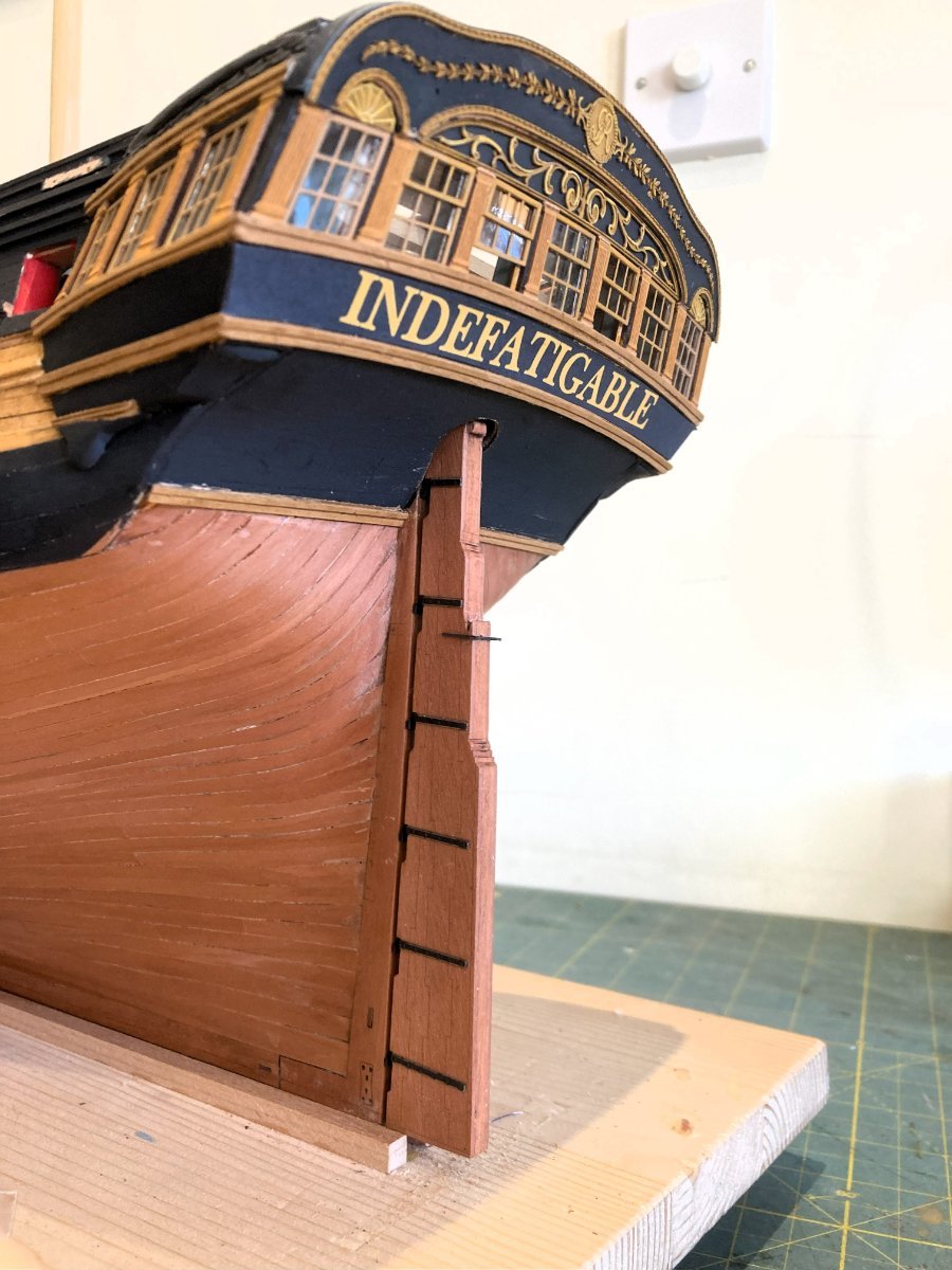
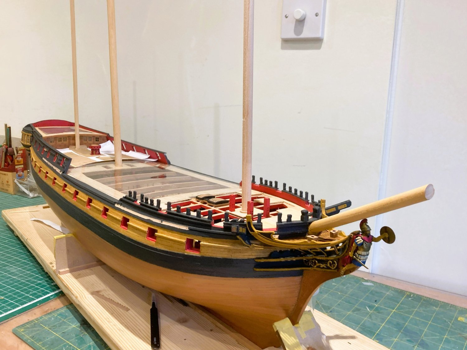
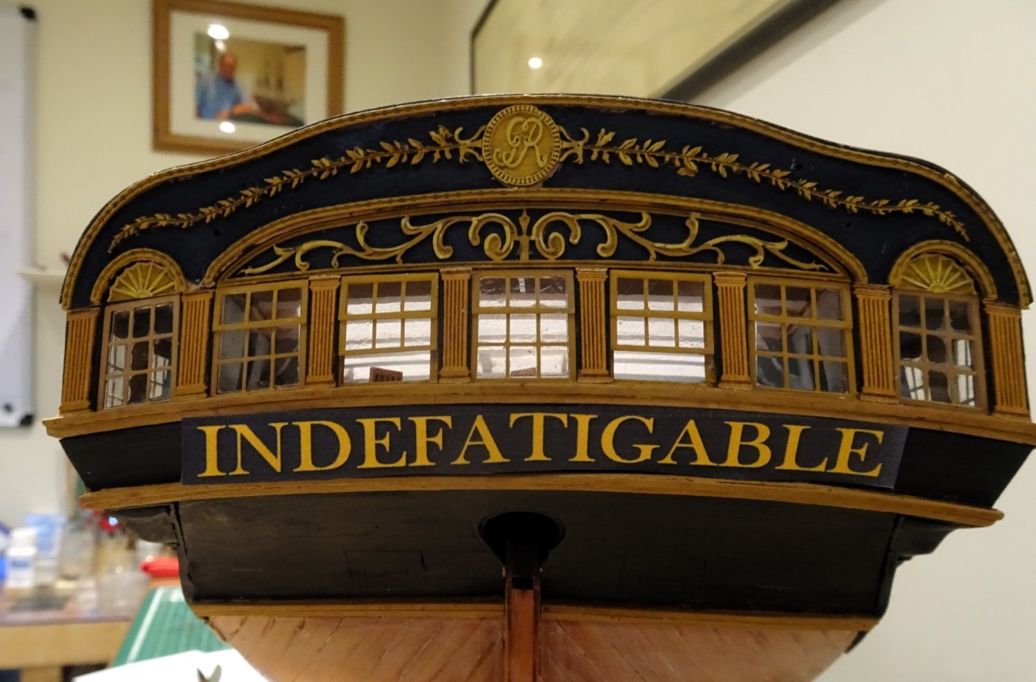
Post One hundred and Twenty-three
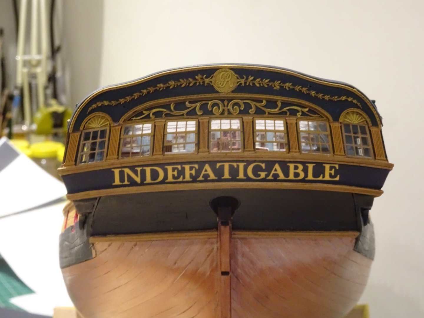
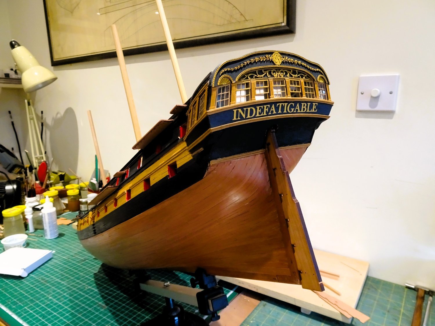
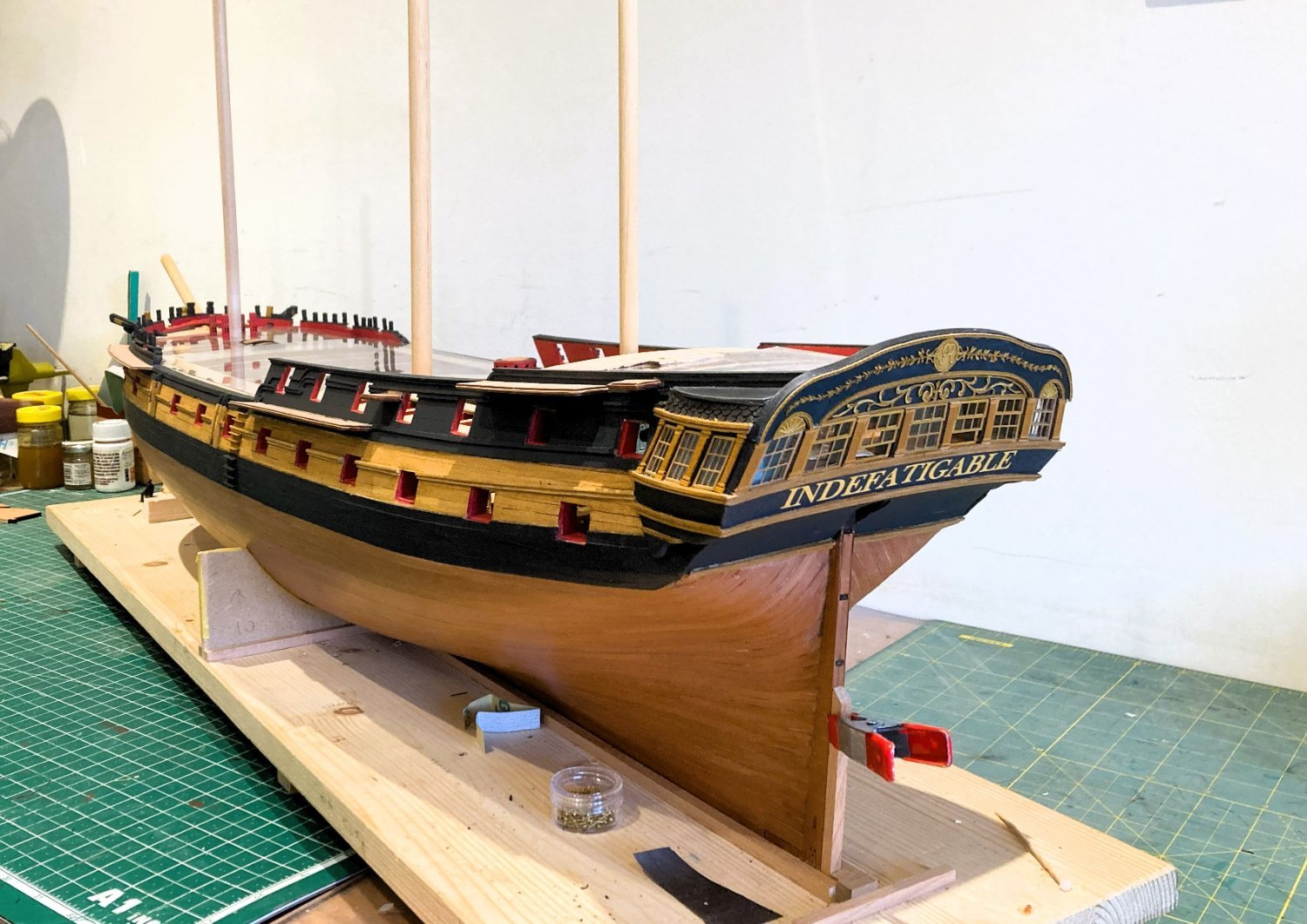
Naming the ship.
The kit provides a water-slide decal for the name with a spare just in case you mess it up.

001
An issue for me is that the lettering colour, fine for the kit indicated scheme, is a little bright for my scheme.
I decided to create my own version on word incorporating a curve to match the counter.
I chose Baskerville old face at 36pts which equates with the kit provided version.

3155a

3155b
I created two types as above.

3153
The solid background version was tested for fit on the model.
The background match to the stern paint looks pretty good to my eye.
Previously I have used Letraset dry rub transfers, a method I like, but I can’t seem to find the correct size or font in this medium.
Maybe just as well, with a name of thirteen letters, accurate positioning could prove a trial.
I have decided to go old school and use the printed version applied over the counter.
I did this for Sphinx, after Chuck’s ‘Winnie’ build, and that turned out well.

3160
The print was sprayed with fixative before cutting out using a template from the plan.

3170
I used spray mount applied to the back of the cut-out to fix into place.
3163
I think I could have imparted slightly more curve to the first and last two letters but overall, I like the look.
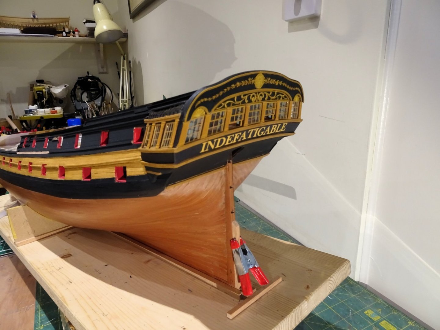
3168
The important thing is that I have proven the system to myself, and I can re-visit at any time.
B.E.
28/12/2023
-
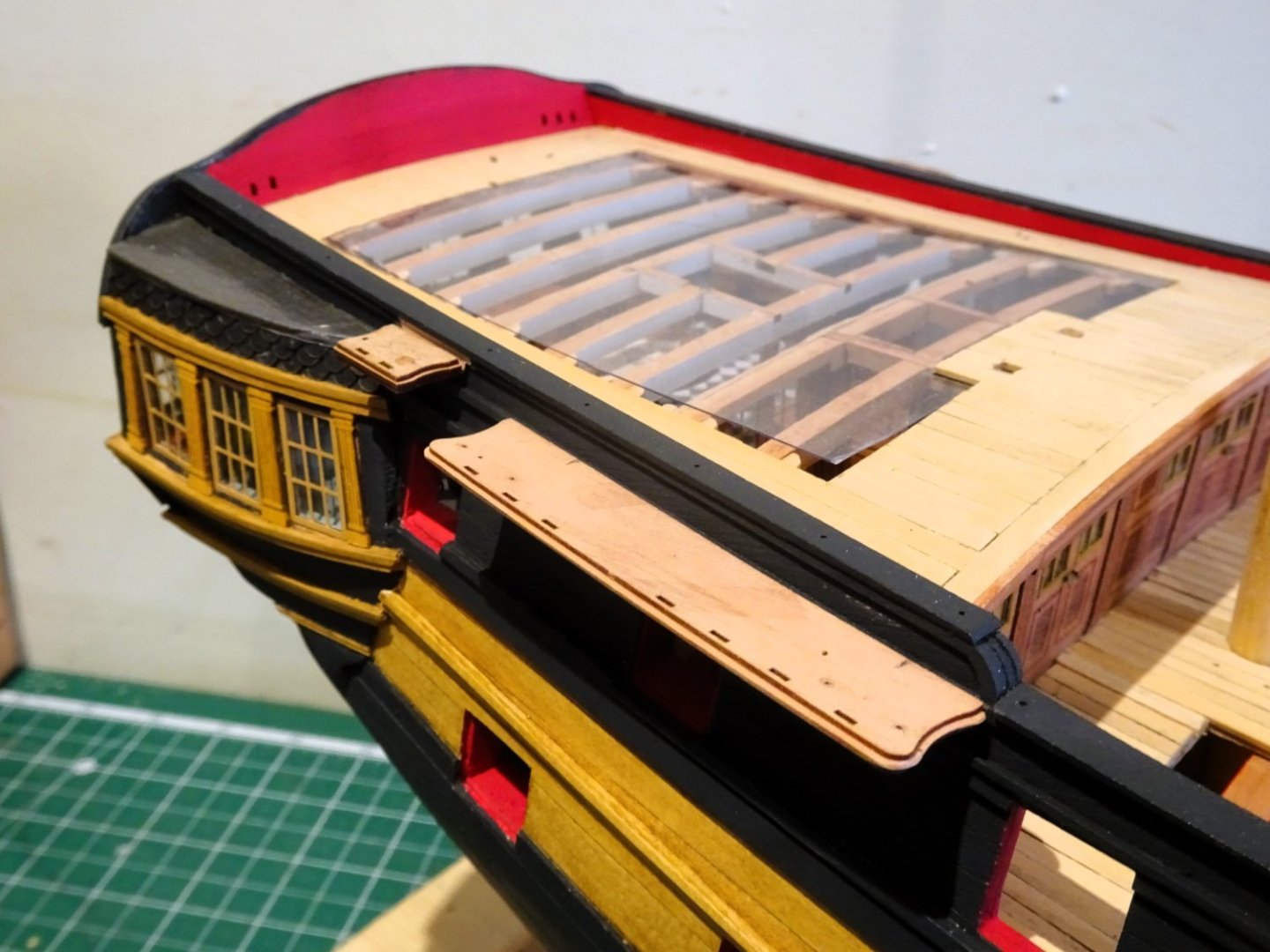
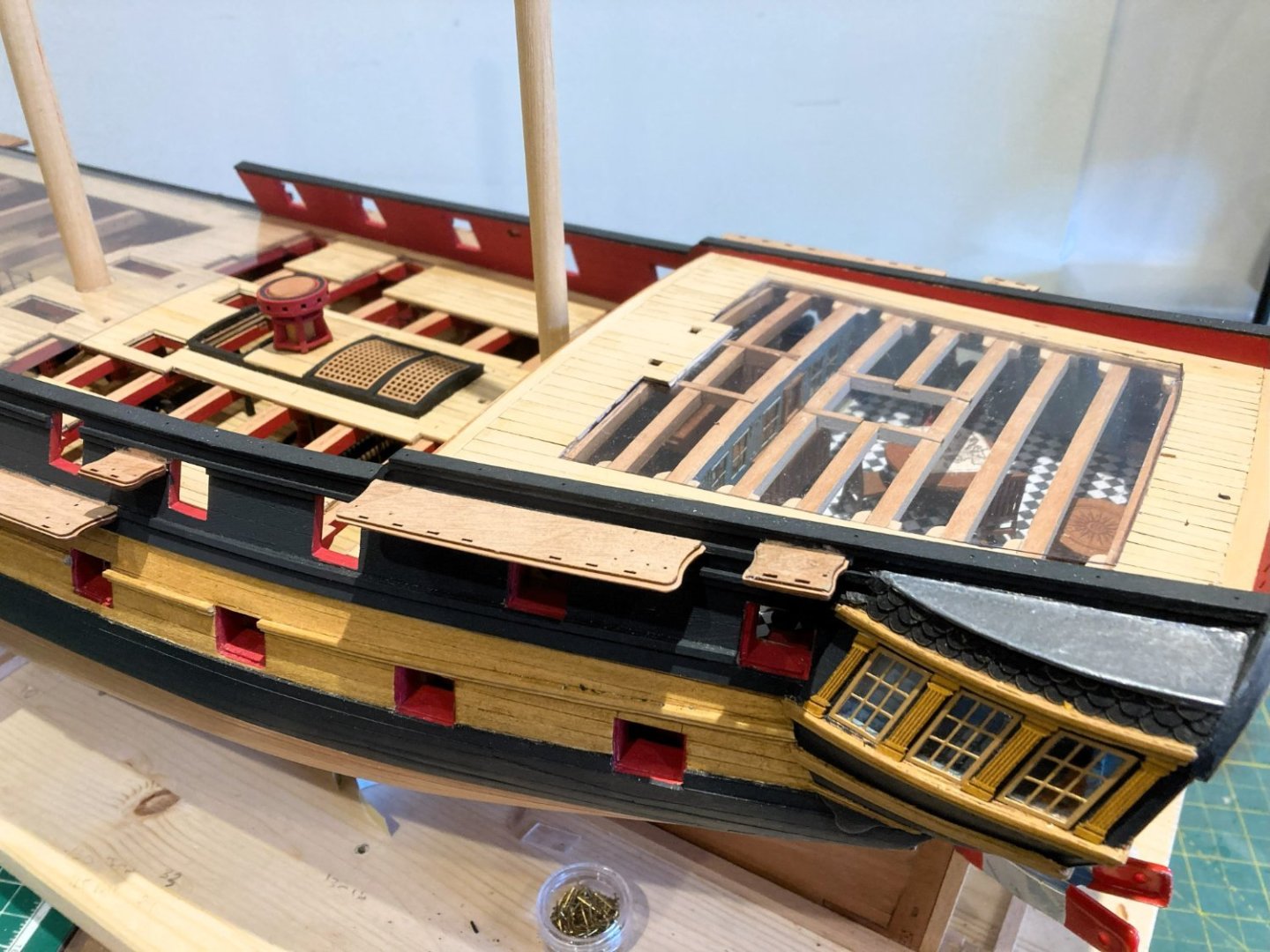
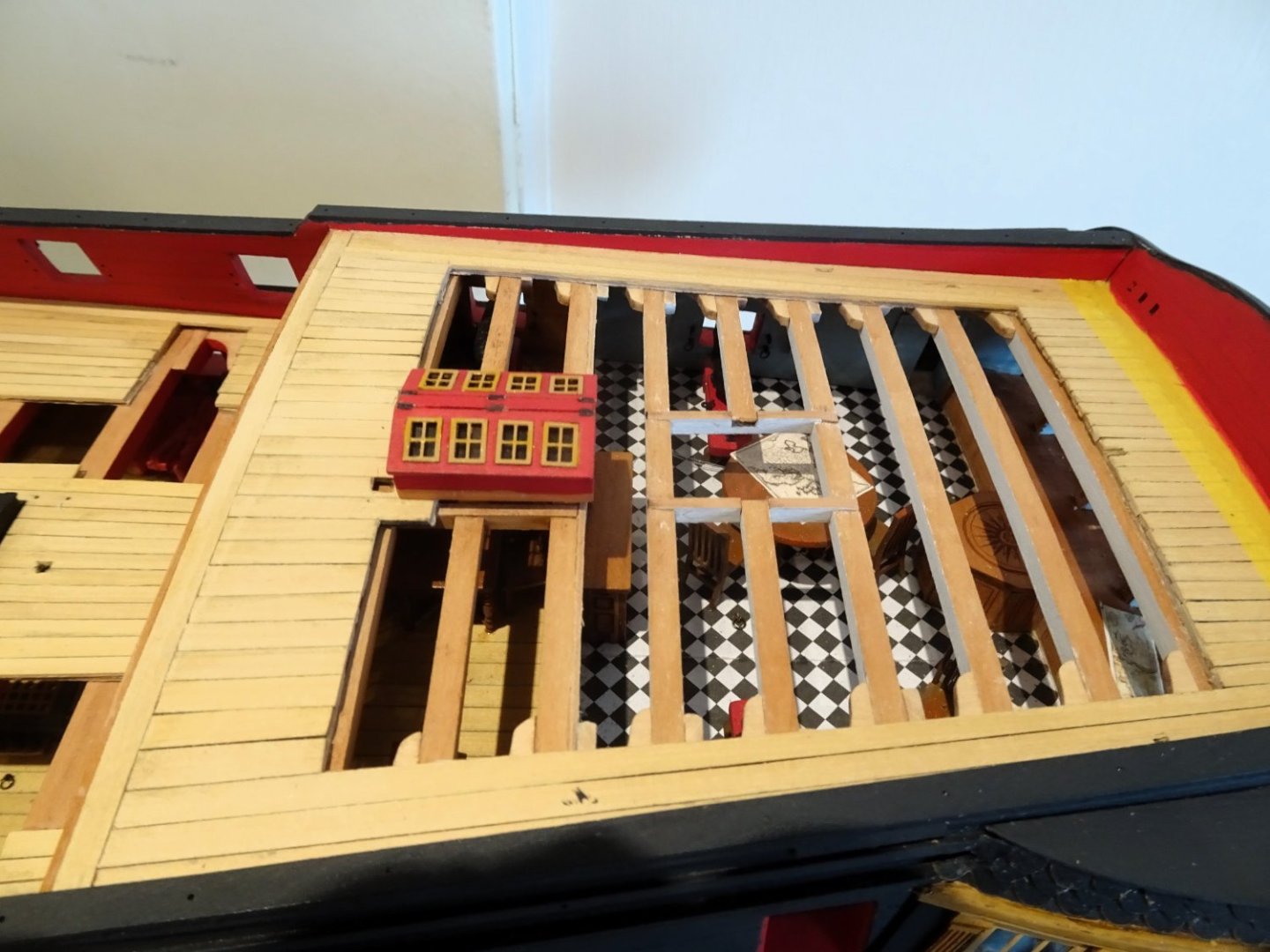
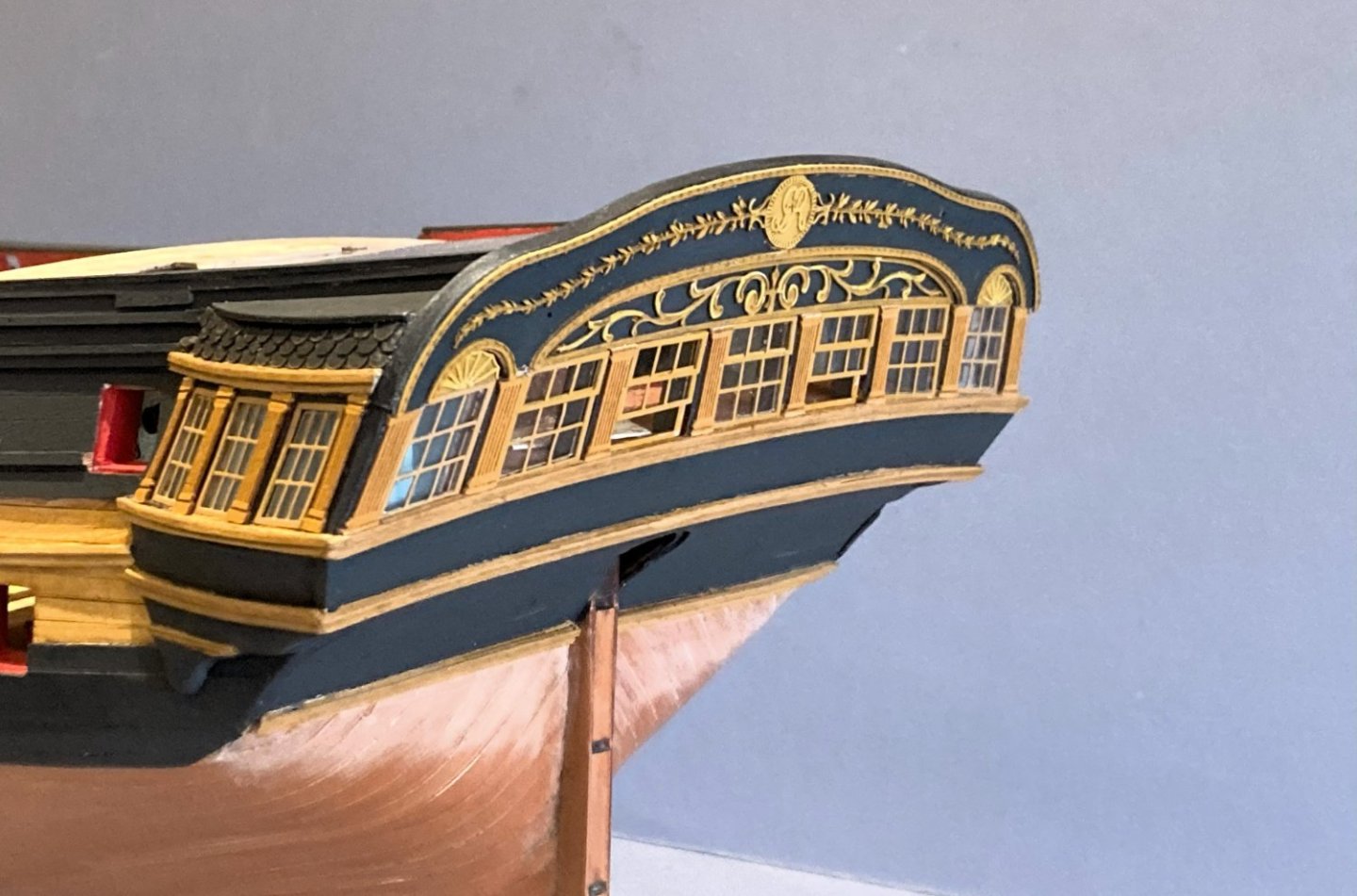
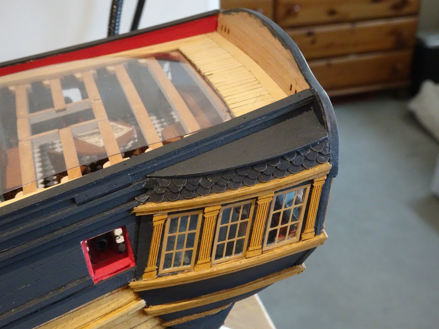
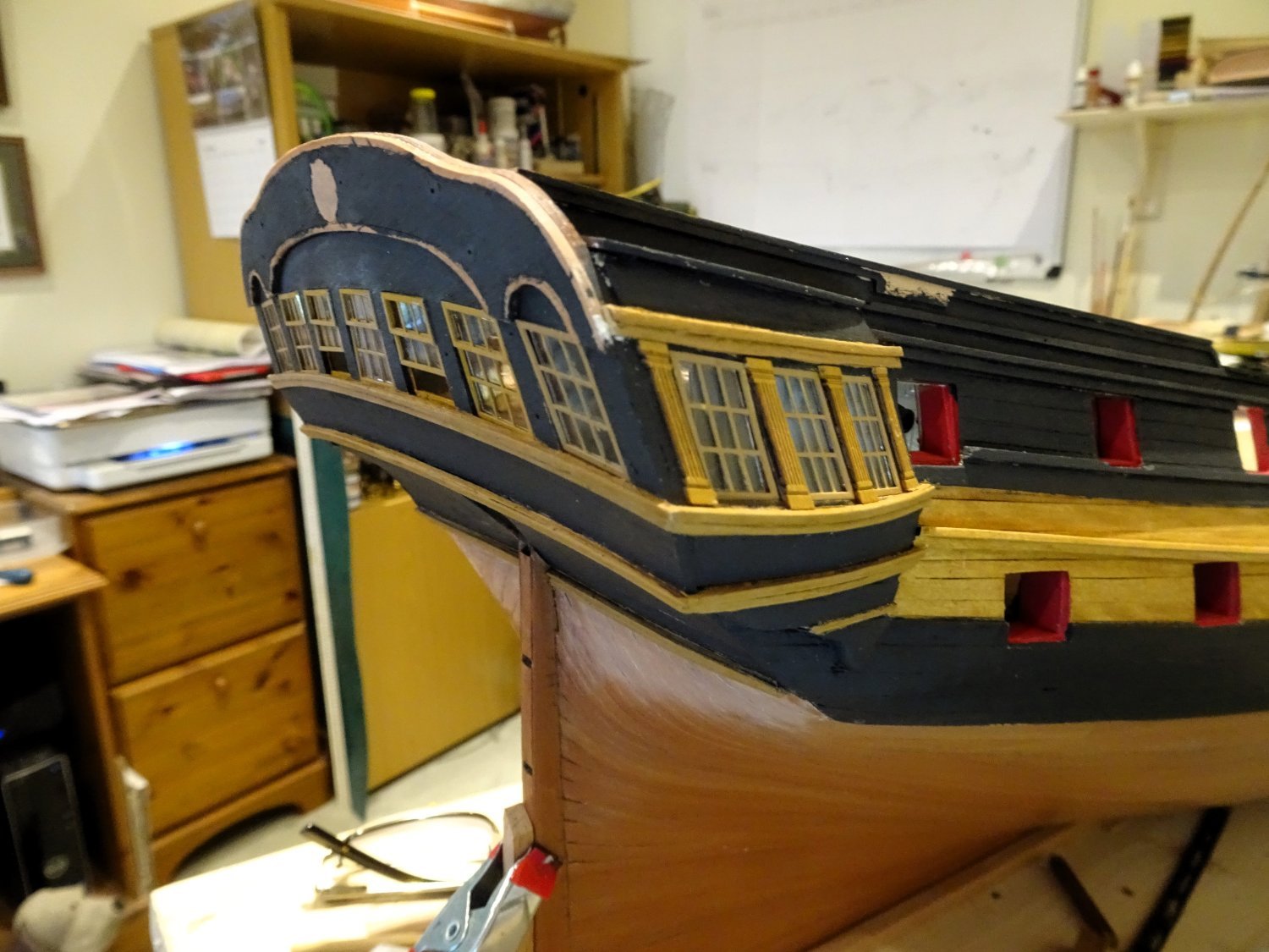
Post One hundred and Twenty-two
Re-visiting the Poop
The position of the skylight is still something of a puzzlement for me.
3141
The original position as indicated on the Adm plans is over the Coach, the standard position for skylights.
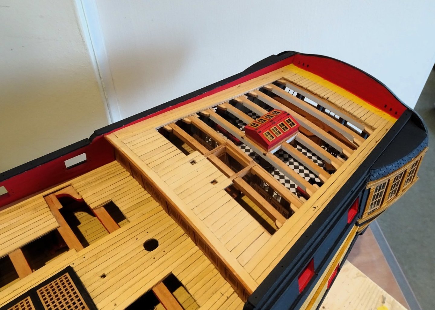
3143
With the shortened Poop deck Chris has re-positioned it over the Great cabin, on the basis that this would be a practical move.
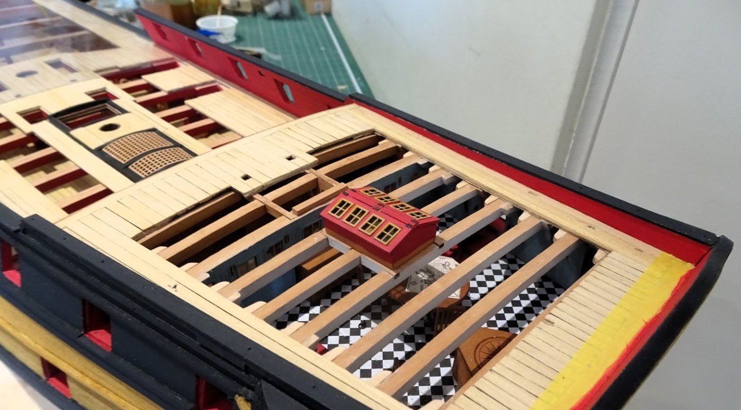
3144
Aesthetically, with the reduced Poop, it looks much better than the usual position over the coach.
The Skylight has been raised by 2mm to compensate for the absence of planking.
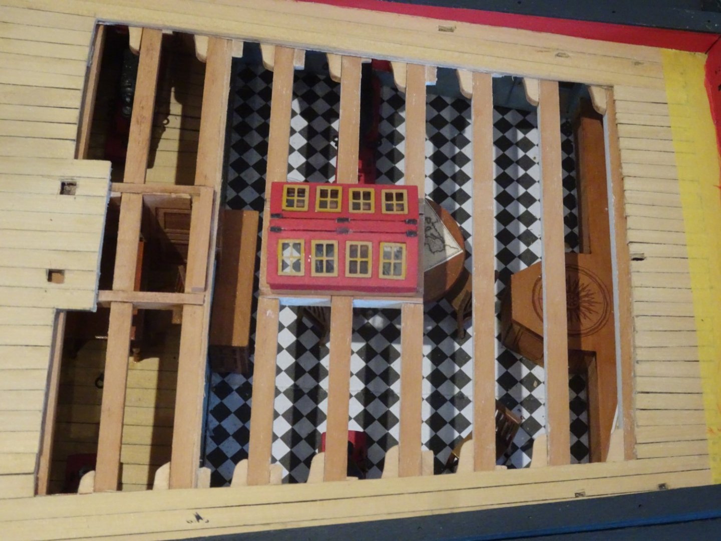
3145
The new position does beg the question whether a skylight over the Great Cabin, with its access to extensive light thro’ the stern, is really necessary.
We do know that Pellew didn’t want the round house at all, but the reduced length was as far as the Navy Board would concede.
Pure speculation, but it seems to me that Pellew might well have dispensed with a Skylight altogether, on the basis that it wasn’t necessary and presented an additional weakness to the structure.
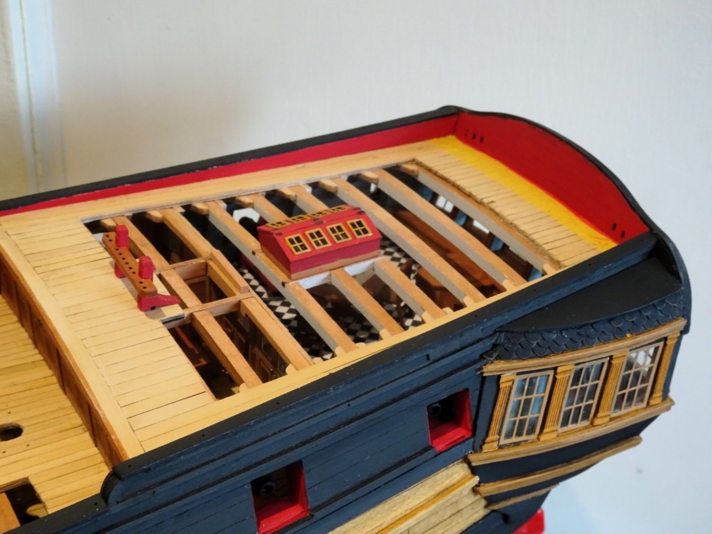
3146
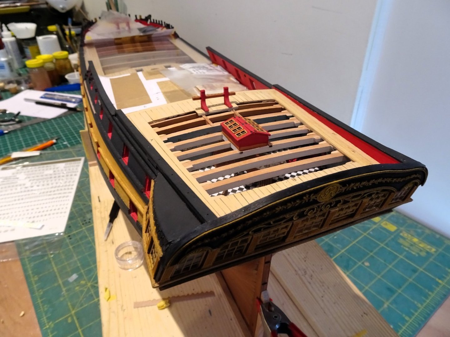
3150
Even so, it is a nice little feature that adds interest to the Poop deck, along with the Mizen Bitts which still seem to be oddly positioned to my eye.
Still ‘Indy’ is a knocked about Sixty-four, so who knows.🤔
B.E.
26/12/2023
- mgatrost, jpalmer1970, gjdale and 24 others
-
27
-
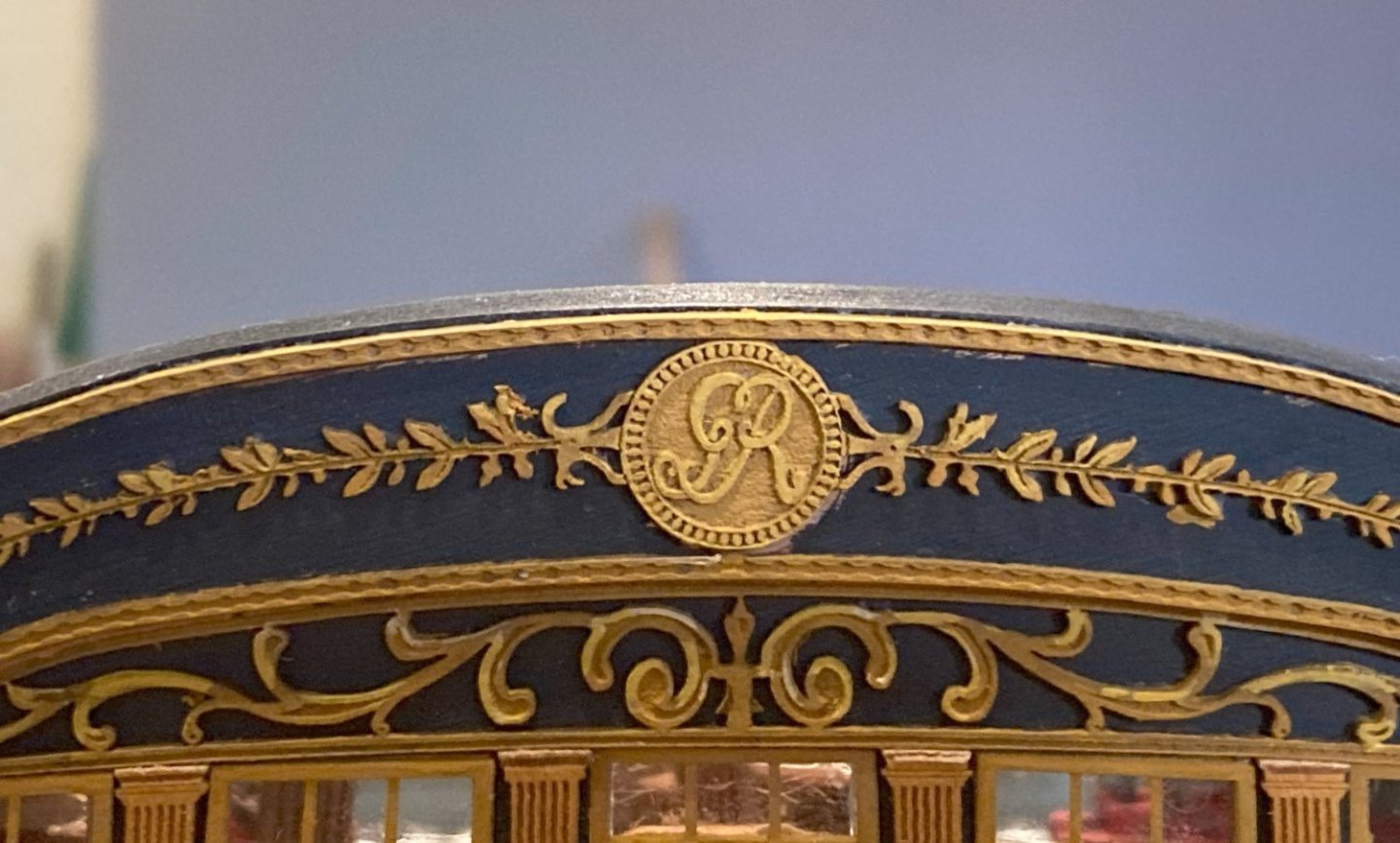
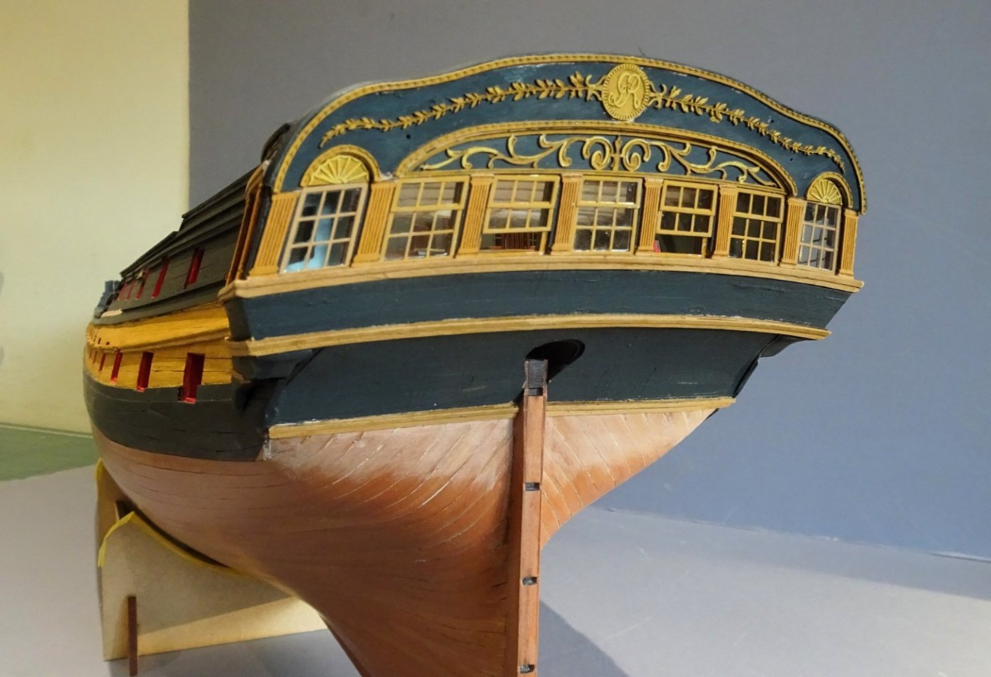
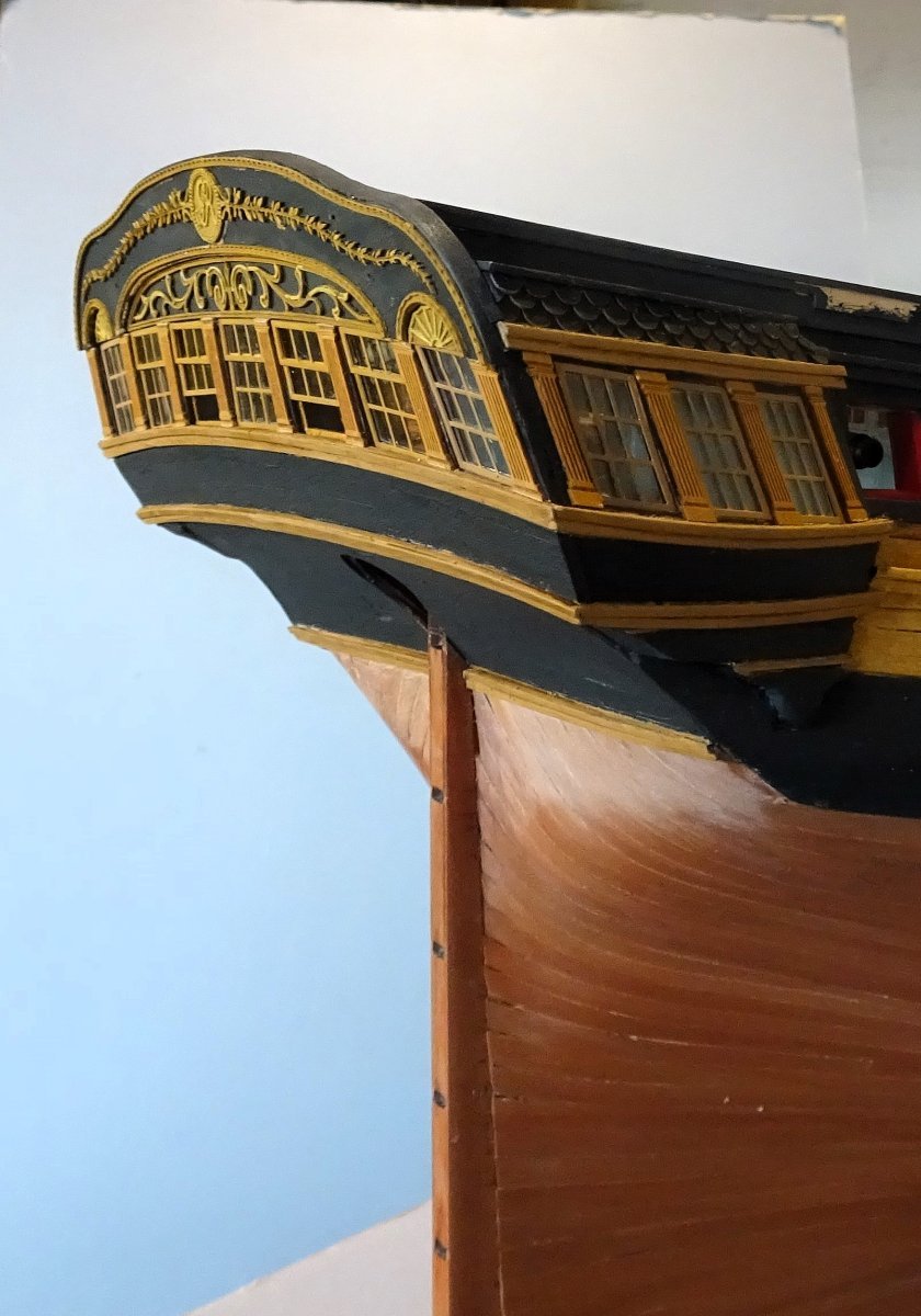
Post One hundred and Twenty-one
Completing the stern decoration
This comprises Acanthus leaf designs and a plaque with the Royal cipher.
 3109
3109
Before I fitted the pilasters between the lights, I added the decoration for the cove.
I found it best to do this before fitting the pilasters.
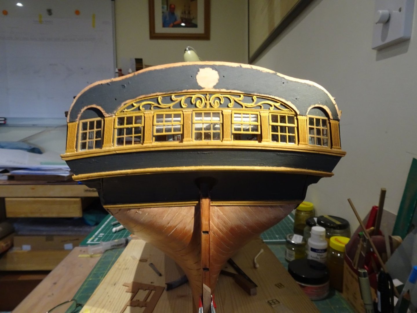
3108
The Pilasters did need a light sanding across the tops to fit the available space.
3111
I decided to add a capping rail to the transom to hide the laminations of the stern.
On 'Indy' I used Boxwood, but thin styrene strips are also suitable.
Roof shingles
Chris has provided pre-cut card versions that do very nicely.

3113
The lower two strakes were fitted as strips, the upper one individual tiles trimmed to suit.
The remaining stern decoration followed.
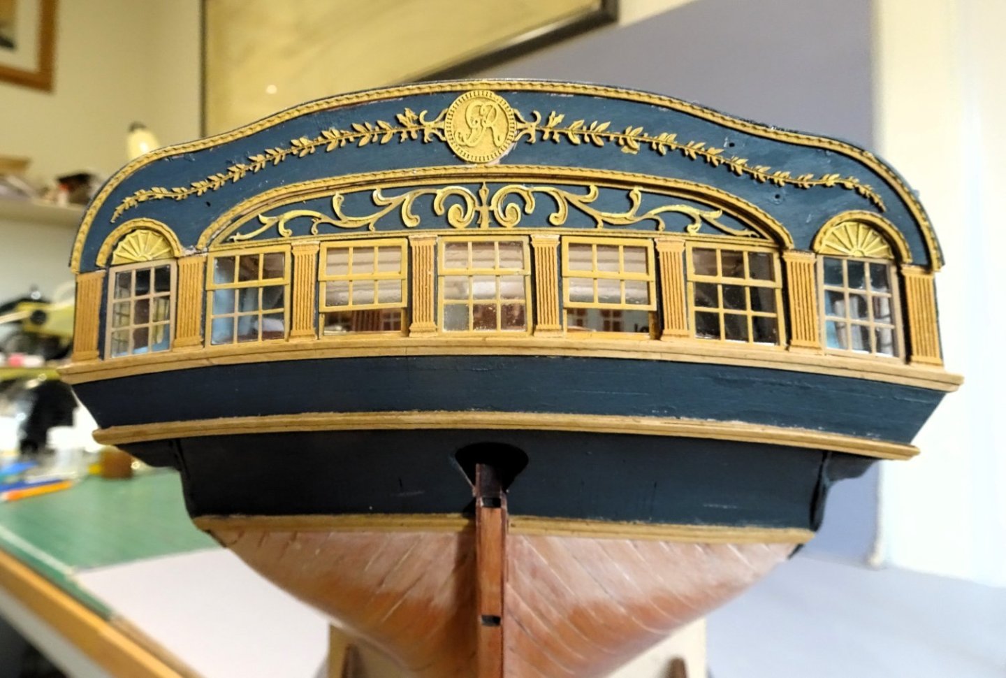
3135
1634A
3133
1639A

3121
3116
This Polybak decoration works very well, but great care must be taken particularly with the long delicate string attached to the cipher.
Break this and there may be difficulties in matching the smooth flow of the design.
My last post before Christmas, so seasons’ greetings to all my fellow builders, and many thanks for those who have liked and shown interest in my builds over the year.
B.E.
23/12/2023.
-
Beautiful detailing Nils, always a pleasure to see your work. 👍
B.E.
- Mirabell61, mtaylor, Retired guy and 2 others
-
5
-
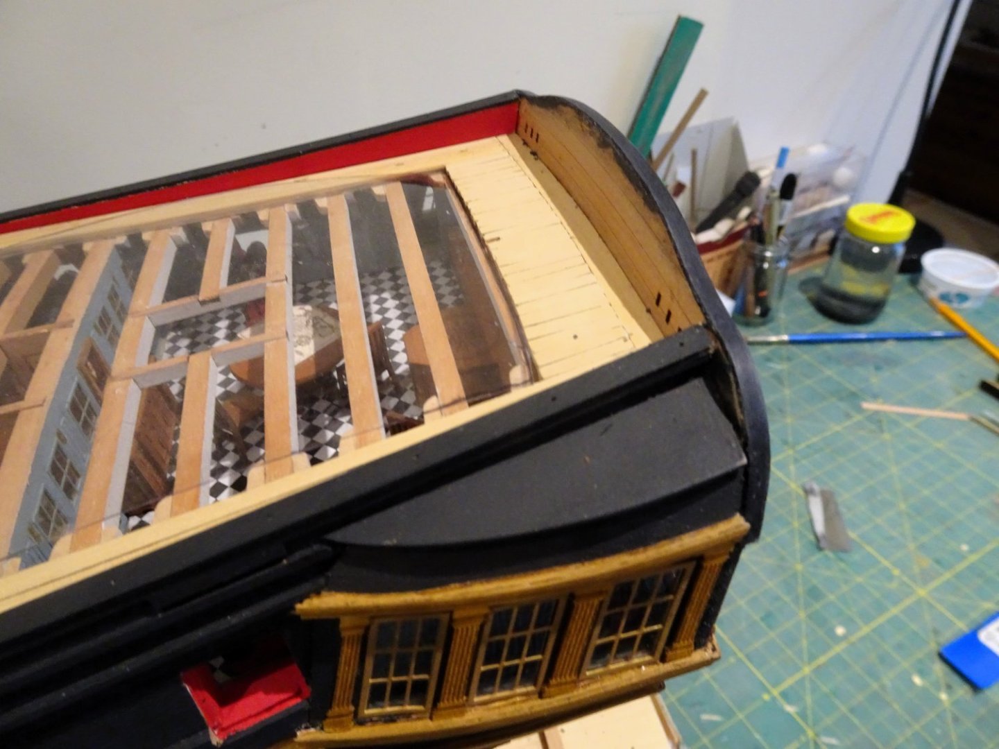
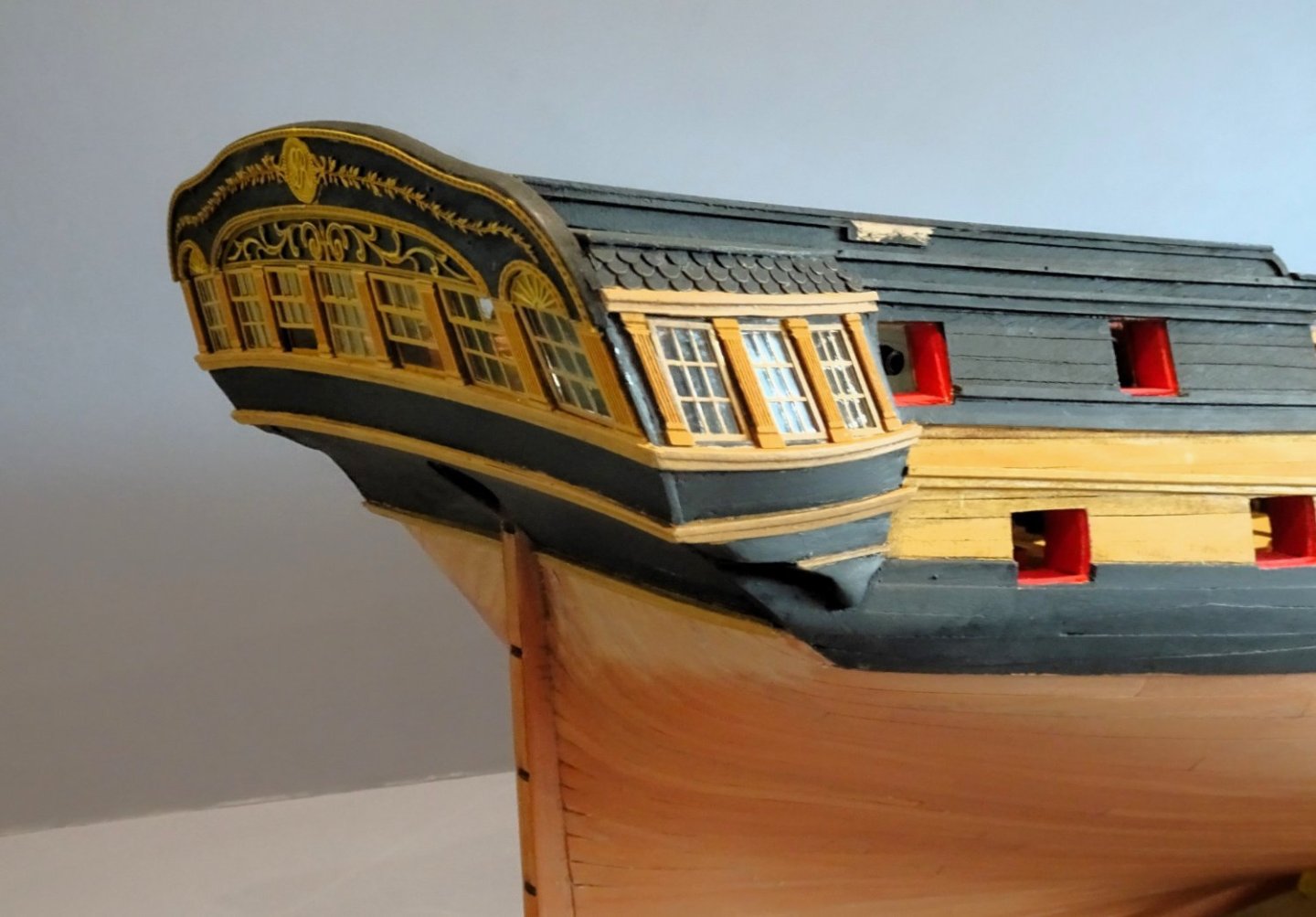
Post One Hundred and Twenty
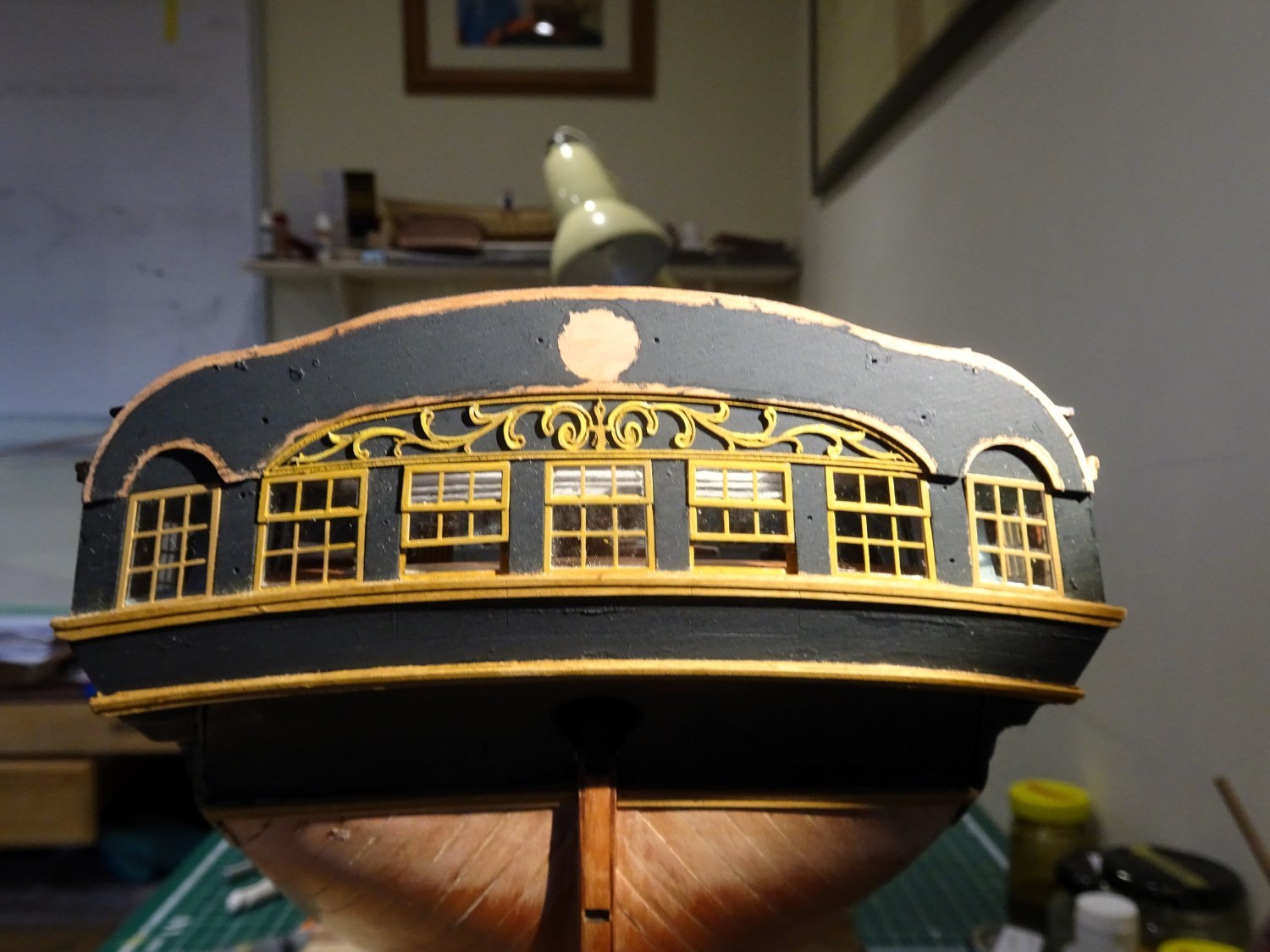
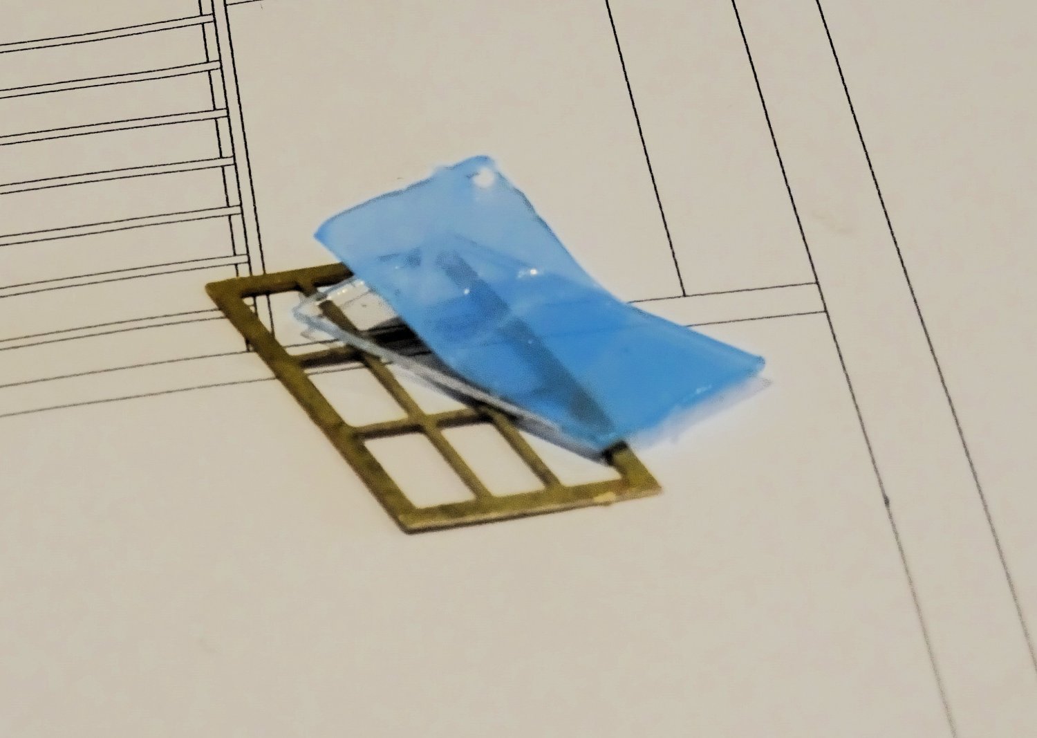
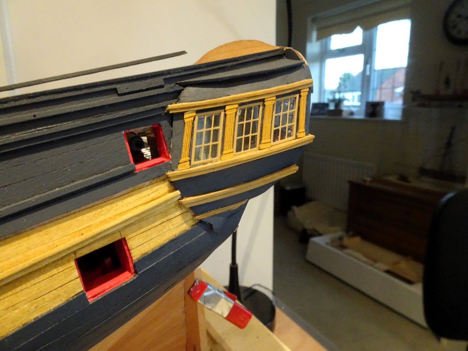
Lights and Frames
I always view this job with a degree of trepidation.
I started by using ‘Future’ (now Klear)
Applied with a brush to the glazing surface the frame was placed on top and allowed to set. Once dry a bead of Future was painted around the reverse edge.
I had mixed success with this.
The Qtr gallery lights were more stubborn and I resorted to applying tiny spots of odourless ca to the back of the frame, and carefully placing the glazing.

3095
I removed the protective covering from the front side, and partly peeled the aft side which I used to hold the glazing for positioning. This ideally needs to be done as a one-shot effort, to reduce the risk of ca spread.
I did have to replace the glazing on several lights due to marring, cut from the glazing fret.
Fitting the frame/glaze combo by comparison is easy, the merest pass along the edges with a file, and they do indeed ‘pop into place.’
I started with the Qtr lights, and once they’re fitted it makes a significant difference to the look. This is Chris’s best Qtr Gallery innovation to date, the seat of ease is clearly visible and with the Gallery door left open the light flows thro’ enhancing the realism.

3103

3105
Addition of the fluted pillars completes the effect.
For the stern I opted to have only two of the sashes open as per Jim’s prototype build, I thought this gave the most balanced and aesthetically pleasing effect.
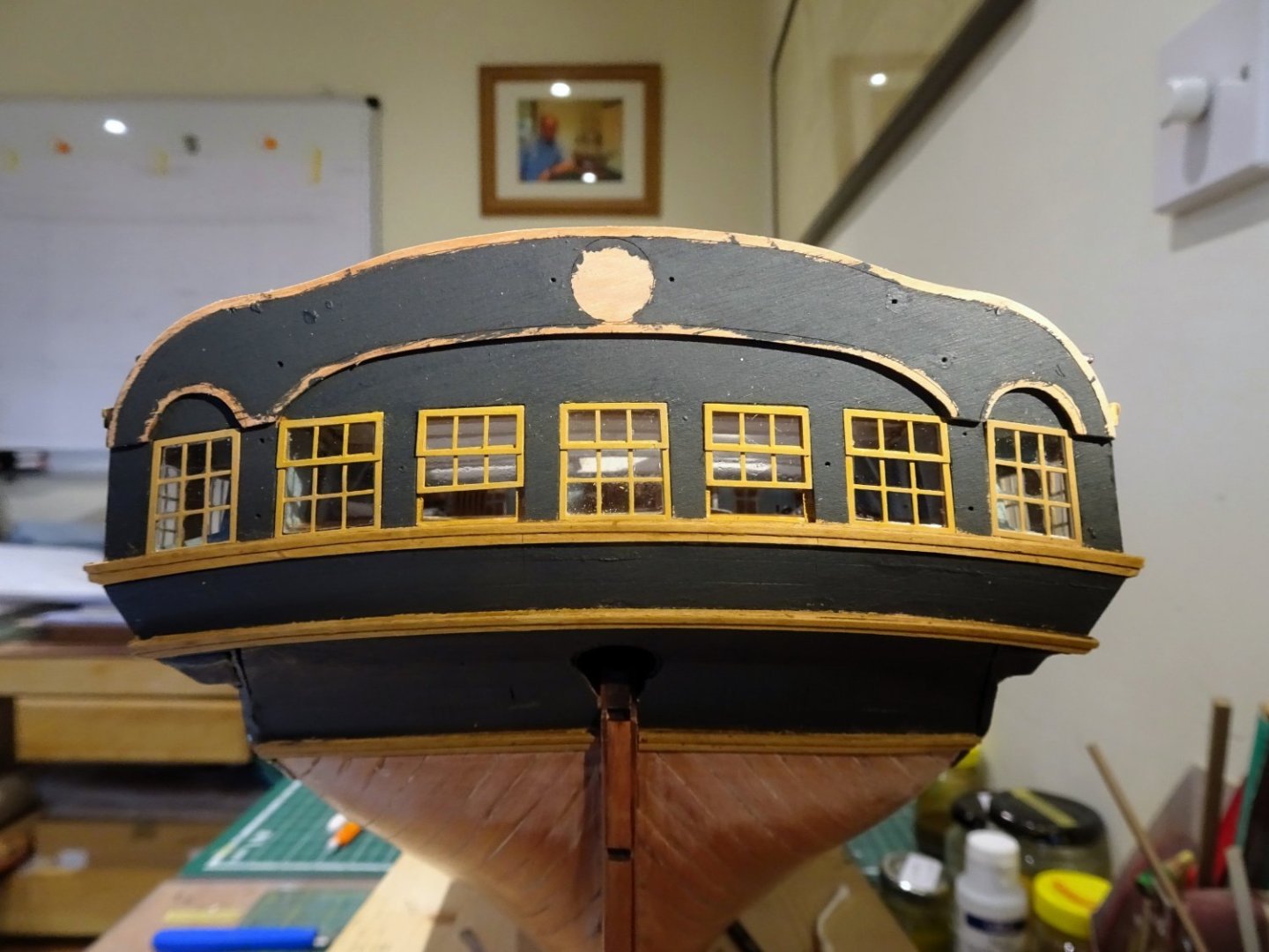
3101
All the stern light glazing pieces were attached to the frames using ‘Future’ prior to fitting. The Upper sash frames were attached to the frames using odourless ca.

1620a
Onto the decoration.
B.E.
22/12/2023
-
Nice work on the rattlin' down Glenn, no hint of shroud distortion. 👍
Personally I'm not keen on inking the ratlines post fitting for fear of ink spray on the decks.
If I'm going to blacken the ratlines I dye the line first, but on my version I'm spared that task.
The decks look nice and shipshape.
B.E.
-
HMS Indefatigable - 1:64 scale – The Art of Age of Sail
I just randomly came across this, another 1:64 scale kit out of MarisStella
To early to say how it will compare with Vanguard's kit, but there are some photos on the link above.
B.E.
-
Thank you, James,
I’m aware of ‘Klear’, or ‘Future’ as it was called last time I used it, beloved of model aircraft builders for canopy fixing and finishing.
I’ll certainly give it a go with odourless ca as a back-up.
Regards,
B.E.
- Mr Whippy, BLACK VIKING, CiscoH and 1 other
-
4


.JPG.d73b914b1b54e495e170910f79178867.JPG)


HM Cutter Alert by Thukydides - Vanguard Models - 1:64 - first build
in - Kit build logs for subjects built from 1751 - 1800
Posted
Very nicely done Daniel, it's always the eyes that give me the most trouble.
B.E.