


Roger Pellett
-
Posts
4,519 -
Joined
-
Last visited
Content Type
Profiles
Forums
Gallery
Events
Posts posted by Roger Pellett
-
-
Thanks, all!
I’m still Collecting information. This is a long term project. It looks like fun.
-
Ok model railroaders, help me out.
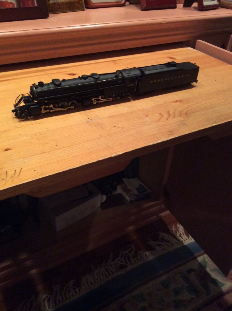
I received the Rivarossi Mallet 2-8-8-2 locomotive today. I have wanted to own a Mallet ever since seeing the one in the Henry Ford Museum years ago. This interest was only enhanced when I moved to Duluth as they, and their even larger brothers the Yellowstones hauled iron ore from the Mesabe Range mines to the ore docks in the Duluth Harbor. While browsing on EBay I found this one at what I considered to be a reasonable “buy it now” price.
So, what’s the problem?
I don’t have an HO layout and know nothing about HO model railroads. My last experience was Lionel over 65 years ago. This was, for me a completely frivolous purchase. I have a couple of ideas:
Buy 3 ft of track, ore cars, and a caboose finish all in DM&IR colors and leave it as a static display. How do I refinish the “Pennsylvania” tender without damaging it?
Same as above, except make a bare bones out and back layout along one wall of my basement/ man cave. No scenery, I just get to watch it run. As this came without paperwork, I have no idea how to make it run or if it can be rigged with sound.
Comments Appreciated!!
Roger
- Egilman, Ryland Craze, Jack12477 and 5 others
-
 8
8
-
If you’re anxious to get started on your model, you could pour it down the drain! 🤣
Roger
- Landlubber Mike and mtaylor
-
 2
2
-
-
I second the Minicraft tools if you can find them. I have the green power supply in the picture above as well as one of their drills. Works great; true variable speed. The Minicraft power supply that I have does not interchange with Proxxon; two prongs vs three. I have been able to buy adaptors that let me use Proxxon tools with my Minicraft power supply.
If you can find a Minicraft drill and an adaptor it should work with a Proxxon power supply.
-
Skipjacks were owned and operated by independent sailors called “Watermen.” They lived along the shore and on the Islands of our Chesapeake Bay; away from big cities. The boats were built by small boatyards in this same environment and sometimes by the Watermen themselves. Americans living in these environments tend to be very independent and very good adapting to local conditions, sometime with unusual solutions. There were no rules, each boat owner doing his thing.
Oysters are not harvested in the summer. We used to say that they were only available to eat in months with names containing the letter R. This means that Skipjacks worked throughout the winter. On the other hand, the Bay water is brackish; mildly salt, so ice that formed would not be heavy. Skipjacks working in waters where ice was expected to form would have light gage steel sheet nailed to the bow along the waterline. Others working farther down the Bay in saltier waters might not have needed this protection.
Roger
- thibaultron, mtaylor and Jack12477
-
3
-
Not a special blade but a different one that I am using for wood. When I bought the saw many years ago, I bought a very fine toothed blade; 300+ teeth, assuming that a finer toothed blade would be better for smooth cuts in wood. It didn’t work well for wood but is perfect for sheet brass. Cuts are distortion free.
Roger
- MEDDO, EricWilliamMarshall, TBlack and 3 others
-
6
-
I don’t know if anyone mentioned this but my Byrnes Saw is a great tool for cutting thin brass sheet. I also have been using it to cut brass angle and channel shapes from square or rectangular brass tubing. Like anything else care and wooden fixtures are necessary to keep fingers away from the blade.
- BobG, bruce d and Landlubber Mike
-
3
-
A low budget alternative. Begin the research to build a model from scratch. Buy a used or inexpensive reprint version of one of Howard I Chapelle’s His History of American Sailing Ships or the Search for Speed Under Sail are both good choices. Each of these books contains several lifetimes of modeling. After reading the book, pick out a ship that you especially like. The plans for HMS Badger are included in the Search for Speed Under Sail. If you are careful, at this point you have probably spent less than $20.00.
Order the plans for your selected vessel from The Smithsonian Institute, the keepers of Chapelle’s work. If the drawing is in one of his books, they probably have the original drawn at a reasonable modeling scale. By now you have spent a total of less than $50.00.
Buy a large sheet translucent drafting media; I like frosted Mylar. You will also need a straightedge such as a metal yardstick, a drafting triangle and a French curve. Probably another $25.00.
Therefore, for less than $100.00 you’re ready to get started.
Using your drafting tools, trace the full sized pieces that you need to build your model as if you were assembling a kit.
Hopefully, you were able to finance the $100.00 start up cost from day to day income leaving your retirement stash intact. Use it to outfit your shop.
Roger
-
Hakan,
I am assuming that you have not abandoned this project so my comments are still relevant.
With regard to the inside-outside planking problem , I suggest a different approach.
First using the drawing that you have, construct a table of offsets. An Excel Spreadsheet works for this. These offsets will be to the outside of the planking.
Now, you need to correct each offset for planking thickness:
The amount that you need to deduct is not always the actual plank thickness; it’s the thickness, corrected for the angle that the plank makes with the frame. To do this you need to add two more columns to your spreadsheet; the vertical and horizontal angles that the plank would make with the frame at each offset point. I have found that these angles can be eyeballed in 15 degree increments; close enough for our purposes.
Using basic trigonometry functions, apply these angles to your plank thickness. This is your correction factor. It will be more, less, or in a few cases equal to planking thickness.
Deduct the correction factor from its corresponding offset point.
Re-plot the offset points. You will also have to refair as some data points may not match up exactly.
This will give you a new lines drawing to inside of planking that is more accurate than just deducting a constant plank thickness. It also doesn’t require dealing with your idiosyncratic CAD system.😏
Roger
-
Make yourself some small wooden pegs. The round cocktail toothpicks from the grocery store work as raw material. Drill through the plank end into the stem/ bulkhead. Dip the peg into your Titebond and peg the plank end in place. This is in addition to the glue applied to the plank itself.
-
Ras,
You’re doing great. You might, however, wish to reconsider polished brass portholes. On many steel ships, the “porthole” is a brass or steel casting bolted to the inside of the plating. The hull plating covers up the brass. See photo below. There were ports where a flanged brass fitting was bolted to the outside of the plating. In this case the brass ring would show. Unfortunately your drawing probably does not provide this level of detail.

-
Mariadoc,
I’m amazed at what can be done with cardboard, and you’re doing it well.
Your pink would not, however, have had a square transom. One definition of a Pink was a vessel where it’s wales terminated at the sternpost. All planking, up to the extension extending behind the sternpost would bend around to land on a rabbit cut into the sternpost; just like the bow.
-
Gaetan:
I would love to have a Bridgeport too but for me, and I suspect many other modelers too it’s beyond reach; too expensive, a major project to get moved into my shop, the cost of building building a foundation, and adequate electrical service. I also find the sheer size and complexity of one of these industrial grade machines to be intimidating.
I use my Toolkraft drill press bought new 50 years ago, almost daily; I use it to drill any hole where I can get the piece under the drill. I have even resorted to a step ladder as an extra support for long pieces! The chuck will not close on drills smaller than 3/32in so I chuck them in a pin vice. I have used this technique to drill holes down to 1/32in dia. The point that I made in a previous post above is that these new bench top drill presses sold by big box stores offer a lot of “big bang for the buck”. Will they still be going strong 50 years from now? Maybe not, but we live on a world where a 5 year old cell phone is considered to be obsolete by many other than me.
I agree that it is difficult to use a conventional drill press to drill very small holes. The mechanical advantage of the drill press lever makes it easy to buckle and break tiny drills. I would think that the same problem would exist with the Van Da Lay Dremel Tool combination posted above.
Rather than purchase full sized machine tools, I bought A Sherline lathe and milling column. To this I added a sensitive drilling attachment. This avoids the mechanical advantage problem and attendant drill breakage.
Roger
-
-
I was killing time last week at our local Menards store while my wife was spending quality time 😠 at the nearby Target Store, so I did some browsing in their power tool department. Menards sells a 10in belt driven multispeed bench top drill press for less than $100; motor included. The unit is equipped with a 1/2 in capacity Jacobs chuck. The unit is compact enough to fit into a small workshop but large enough for serious work. To use it with small wire size drill bits a set of pin vices could be added; easily chucked into the Jacobs Chuck.
I am not promoting Menards, and have no connection with the company. I assume that similar machines are available elsewhere if you look for them.
Roger
-
-
The clamps in question are called “C Clamps” or in Great Britain “G Clamps.” A well equipped shop never has enough of them. They are readily available commercially in sizes from 1/2 in to over 12in. Any store selling tools should offer a selection. Mine range from 1in to 8in and I use them constantly, from clamping tiny brass parts for soldering to clamping an entire hull under my drill press.
Much of what I know about woodworking, I learned from my father, a builder of Ship models, boats, buildings, and even an airplane. He taught me when clamping wood to always include wood padding under then clamp screw to avoid marring the surface.
Roger
-
Shipbuilders did not work from plans to build the actual hull. They worked from patterns developed on the mould loft floor. These patterns were developed from lines laid down on the floor. These lines, a full sized copy of the Master Shipwright’s draught or Naval Architect’s lines were drawn on the floor from measurements provided by the designer; a digital map of the hull shape.
Books on lofting are filled with geometric construction techniques to avoid actual measuring where possible. Straightedges, compasses, and chalk lines were commonly used.
As construction progressed, specialists, each with their own tools and measuring devices, applied their trades requiring varying degrees of accuracy. This stage of construction also had to take into consideration tolerances for work that had been done before.
-
This forum is owned by the Nautical Research Guild. The Guild’s motto is Advancing Ship Modeling Through Research. As a long-standing (46 years) member of the Guild I completely endorse the Guild’s mission to encourage construction of quality models.
During the last few years, the quality of kits available to model builders has improved considerably. Old line companies have redesigned their offerings and several new companies have emerged, and hopefully they will be supported by kit builders. In my opinion, the commercial ship model business is like any other business. Competition improves the product. Advertising (sponsorship) in this forum is no substitute for providing less than top quality.
Roger
-
I not only use the Imperial system of measurement, I think it. If someone gives me a metric dimension, it makes no sense unless I mentally convert it into feet and inches. If someone mentions a 75mm gun, my brain automatically tells me, “that’s about 3in.” Like Allen, using original drawings of American vessels measurements are in feet and inches. I have tried to get into the habit of taking measurements directly using an architect’s scale. 8 ft on a drawing is measured at the correct scale as 8ft on the model.
During my working career I worked on some industry standards committees for piping components. Many American standards have been converted to metric using “Soft Conversions.” For example 6 in pipe becomes 150 Nominal Diameter Metric Size. The actual pipe diameter hasn’t changed; it’s still 6-5/8in.
Roger
- Rik Thistle, Canute and mtaylor
-
3
-
Bill,
Sherline is Lionel Trains for big boys!😁. You can never have too many accessories. I’ll add that to my list. Thanks.
Roger
- Canute, Bill Hudson and mtaylor
-
3
-
-
Make a “Plating Expansion.” BC, before CADD, Draftsmen In shipyards made these drawings for ordering plates from the steel mills. While you don’t have to make an actual drawing you can use the same idea.
First, divide the hull into regularly spaced intervals, and mark each on your hull from keel up to the upper limit of your plating. Also mark the upper limit of the plating. You only need to do this on one side. Think a half model.
Cut out a bunch of paper strips.
Wrap each paper strip around the half hull vertically from keel to the upper edge of the plating. Mark the location of keel and upper edge on the paper. Do this for each interval using a separate strip of paper each time.
Multiply each girth measured above, by the interval that you selected. The first and last strips should be multiplied by the distance of that girth measured to the bow or stern as applicable.
Add the results obtained above together.
Multiply this x2.
Add a waste factor


One of the proposed alternatives to the Panama Canal
in Nautical/Naval History
Posted
Drydocking a ship is complicated, as care must be taken to avoid straining the hull. Stability must also be considered since as the water level recedes the vessel’s hull geometry changes. It would also be unusual for a vessel to be drydocked in the fully loaded condition. For these reasons, drydocking plans that specify how the vessel is to be supported during docking are prepared.
Overcoming these problems for each individual ship would be enough to doom this approach.
Roger