


Roger Pellett
-
Posts
4,519 -
Joined
-
Last visited
Content Type
Profiles
Forums
Gallery
Events
Posts posted by Roger Pellett
-
-
Old shipbuilding and seamanship texts often had oversized drawings that folded out or were included in an envelope attached to the book cover or even as a separate volume. In scanning the book for reproduction the person doing the work often doesn’t bother to unfold the drawings, or leaves them out entirely.
The University of Michigan has one of the largest academic libraries in the US, and since they have taught Naval Architecture and Marine Engineering since the late 1800’s their library includes many books of interest to us. They were also one of the first US Universities to begin to digitize their collection. I have bought two books from them: an 1866 US Navy Ordnance Manual and a Naval Architecture text from the same era. Both were of far better quality than the usual imported offerings, and I will continue to buy more, but even these each omitted a drawing.
Roger
- Canute, mtaylor, EricWilliamMarshall and 1 other
-
 4
4
-
Garrett Wade tools $11.50
-
I call that an Archimedes screw drill. I bought mine many years ago (1980’s) from a jewelry tool supplier that came to an NRG Conference. I suspect that you might find one on EBay under jewelers or watchmakers tools.
Also check suppliers of new tools for jewelers. Rio Grand comes to mind.
Roger
-
Feathermerchant:
I just reread Dwight Boyer’s account of the sinking of the Margaret Olwill. People that don’t live near the Lakes, may not realize that these ordinary Lake Freighters often carried passengers; family members of crews, owners and their families, important customers, and guests of all of the above. The Benjamin Noble had a large owner’s suite in her forward. Deckhouse. A shipwreck with loss of life is always a tragedy but even more so when these “civilians” are killed.
In the very early 1890’s the Western Reserve, one of the first steel ships on the Lakes sank on Lake Superior during an August storm. There was only one survivor. Unfortunately the ship’s owner, Peter Minch, was on board with his entire family plus guests. The Minch Family was from Vermilion, Ohio.
-
I’ve never paddled up or down it, but now that I don’t live there anymore, I wish that I had.
-
Woods are like fish, they have different names depending on where you live. The poplar that Jaager mentions is called a Tulip Tree in Ohio, and I agree that it is a nice wood for modeling. Here in Northern Minnesota “Poplar” refers to wood from the Aspen tree, or locally referred to as Popple. These trees take over logged areas and are fast growing but don’t get very large. The wood is used for paper pulp, but is now being stocked as poplar in the specialty lumber department of our local Menards store. It is very soft and unsuitable for quality ship model work.
I have never built a POB kit but suspect that the wood supplied is not true Walnut. American Black Walnut is my favorite wood for ship model cases. It is a nice wood to work with, but not for the models themselves.
-
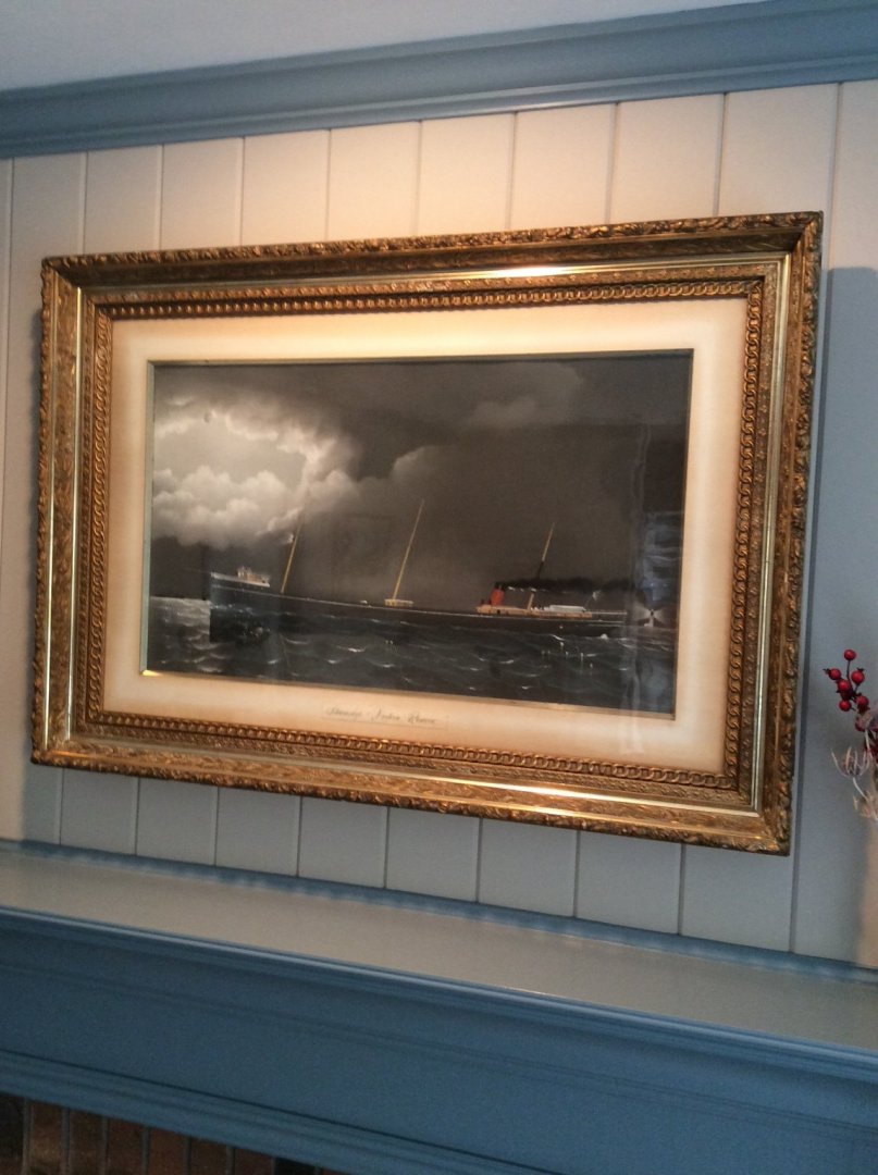
See the current issue of the Nautical Research Journal for more about this Shipyard and a model of a ship built there.
- JKC27, mtaylor, hollowneck and 2 others
-
5
-
-
As requested, a brief description of the Hahn Method:
This method was an outgrowth of Charles Davis’s Built Up Ship Model Book and is based on an assumption, not valid for all real ships. The assumption was that real wooden ships were built with two layer (sistered) frames, regularly spaced, known as “room and space.”
Hahn also had access to a full sized table saw (8in) and plenty of lumber. As a professional model maker, he continued to use his method even after switching to more expensive Boxwood. He was not limited to buying precut sheet stock from others.
The Method:
1. On the sheer view of the lines drawing draw a straight datum line above the highest point of the vessel’s sheer. The datum should be perpendicular to the vertical stations on the sheer view. Project this same datum, at the same height above the top of the body plan.
2. On the body plan extend the top of each station (section) vertically until it intersects with the datum. These vertical extensions will be parallel to the body plan centerline.
3. Loft and vertically extend per 2, additional body plan sections as needed to satisfy room and space.
4. Plot the point where each body plan section extension from 2 and 3 meets the datum on a plan view. Pass a curve through these points. Glue the drawing to a flat board and cut out the shape bounded by the curve. You will use the area outside of the curve.
5. Eyeball the body plan sections and draw standard oversized patterns for the the frames represented for the lofted body plan sections in 2 and 3. These patterns allow the rough frames to be made from straight pieces of framing material with mitered joints between sections. Each rough framing section is constructed in two layers glued face to face. The mitered butt joints in the top layer should be staggered from those on the bottom layer.
6. Rubber cement a copy of each lofted frame onto the rough framing section. Cut out the finished frame.
7. Use the board with the cut out plan view to build a jig to hold the cut out frame sections in the upright position with the frame extensions flush with the bottom of the jig.
8. Glue the frames into the jig. You will be building the model upside down.
9. Add keel, stem, stern, etc. Fair framing, and stabilize hull structure with planking.
10. Cut hull structure from jig along sheer line.
As Jaager has posted, an investment in NRG’s Shop Notes is well worth the $35 cost and includes a complete description by Hahn of his method along with drawings to build a model. He has done all of the lofting for you.
Besides, you support NRG and the forum.
Roger
-
-
The Port of Duluth, MN provides the best long distance rail access to the tar sands oil fields near Edmonton, Alberta Canada. For that reason, during the past twenty five years there have been several heavy lift shipments of very large oil refinery reactor vessels into the port for shipment to the tar sands.
Some of these reactor vessels were heavy enough to require shipment via Schnabel car. The Schnabel car was developed in Germany and used during WWII by the German Army to transport very heavy guns. The car transporting the Thor gun above is an early version of the car. There are several of these heavy lift railroad cars in the US, the largest designed to transport Westinghouse nuclear reactor vessels.
For several years, this particular car was parked at the Port of Duluth to handle tar sands heavy lift traffic; there were no longer any nuclear reactors to deliver. In July of 2005, the company that I worked for received a contract to fabricate special components to modify the car for an upcoming shipment. It required welding some very high yield strength steels. I remember investigating HY80 submarine hull steel.
The heavy lift ship arrived at the port in late summer, with the vessel loaded directly from the ship to the car, but shipment from the Port to Canada was delayed until ground had frozen in the winter.
Roger
-
-
Thanks,
That’s probably the same guy that I found. Even today, the second T at the end of the name Pellett seems to be optional! Thanks for looking it up.
Western Lake Erie is familiar country for me. When I was very young we sailed my father’s home built L. Francis Herreshoff H23 sailboat that he kept at Vermilion, on the Lake. Typical trips were to Lorain, Sandusky, and the Islands. I was mostly wet, cold, and seasick but somehow gained a lifetime love of the Lakes. In the last few years of my father’s life, my parents moved from the Medina, Ohio area to a home in the Vermilion Lagoons. We were living in Marietta then and used make the drive up to visit, so my Great Lakes interest was passed down to my children.
It is remarkable how different the various lakes are. Lake Superior is completely different from Lake Erie and what I have seen of Lake Michigan is different still. I have little familiarity with Lakes Huron or Ontario.
Roger
- lmagna, FriedClams, Keith Black and 4 others
-
7
-
Well, you stumped me! Stowage factors are empirically derived. Although they are related to the density of the material in question, they are also dependent on the amount of air being shipped. For example, cut limestone building blocks that can be stacked edge to edge have a lower stowage factor than crushed limestone for steel making. The tables that I have for stowage factors do not list limestone. They were intended for international shipping and not Great Lakes Cargos. I’ll look through some other references to see what I can find.
Unfortunately, load lines (Plimsoll Marks) were not mandated for ships on the Great Lakes until 1936. Loading was left to the master’s discretion sometimes with disastrous consequences.
I am actually interested in the Kelly’s Island limestone trade. In his wonderful novel Signature of Time about Kelly’s Island, Walter Havighurst mentions the barge James Pellett loading stone at the quarry. I looked it up and found a picture of the barge; a remarkably ugly vessel. I also found that James Pellett was a Great Lakes ship captain sailing in the Kelly’s Island limestone trade.
The Pellett family emigrated to Northeastern Ohio in the early 1800’s from Connecticut, and continued to live in the state until I moved to Minnesota in 1990 and I naturally wondered if I am related.
Roger
- Keith Black, Canute, mtaylor and 1 other
-
4
-
Many years ago, I built a POF Model of the New York Pilot Boat Anna Maria using the Hahn Method. I used Howard Chapelle’s drawings purchased from the Smithsonian, and lofted the frames. It produced a model that I am pleased with.
It can be argued that Hahn himself built a model like you are contemplating. One of his last models, the Ship of Line Alfred, featured the more complex bent frame, filler frame type construction.
While you could use the Hahn method to build a model that from outward appearance features correct scantlings is not suited for building the highly detailed POF models that replicate exact Admiralty construction practice as these models require details such as chocks within the frame structure.
Keep in mind that when you wander from British or French ships builtin Royal Dockyards, ships were often not built with Hahn Style framing. Many vessels were built with widely spaced heavy frames to define hull shape with lighter frames or frame segments added in between. These lighter frames and segments were fastened to planking but not always to the keel.
Roger
- Justin P., mtaylor, thibaultron and 1 other
-
4
-
One of these sunken vessels, the Schooner Dot, was apparently a “Canaller,” a specialized ship designed to navigate the restricted lock dimensions of the Welland Canal around Niagara Falls.
The current issue of the Nautical Research Journal includes the first of a two part article about building a model of one.
Roger
- BANYAN, mtaylor, thibaultron and 1 other
-
4
-
-
This guy pounces as soon as I come through the door. It doesn’t matter what I’m wearing.
- mtaylor, flying_dutchman2 and Canute
-
 2
2
-
 1
1
-
-
Thanks for all of the Likes and comments.
Keith: No, no fruit trees. There is a dedicated green space between our house and those on the next street over. It's swampy and heavily wooded. The trees seen the window are European Buckthorn, an invasive species. Fall comes early here with colors peaking the first week of October. Trees are now bare.
Roger
- Canute, mtaylor, Keith Black and 2 others
-
5
-
I know that you are enjoying “freelancing” this model, but sooner or later you are faced with mechanical reality- does what you are doing actually make physical sense. Such is the case with the windlass. With two cables wrapped around the windlass barrel, how do you drop just one anchor, and what do you do with the unused cable.
Deep sea vessels on long voyages would sail with anchors securely lashed down and cables stored below. The anchor and its cable would only be readied for use when she vessel reached shallow water near its destination. You are building a coasting vessel, that could need its anchors throughout the voyage. It would, therefore, not be unusual to have one anchor set up to be used, with the other on standby as a backup. Windlasses on coasting vessels often were equipped with an arbor or beam extending across the top. This allowed the unused cable to be hung in loose coils encircling the windlass barrel. When the other anchor was dropped the windlass could rotate without engaging the second cable.
I also believe that whenever possible, crews avoided rotating the windlass when dropping the anchor. The cable screaming around the windlass barrel propelled by the weight of the anchor must have been dangerous to both ship and crew. They did this by laying out the required amount of cable in large loops on the deck ahead of the windlass; between the anchor and the windlass. Once the anchor hit bottom, the ship was backed and the cable could be paid out gradually.
Roger
-
Our local Ace has a K&S display and a good wire selection. My only gripe is that the overdo the “Helpful Hardware” business. Whenever I go into the store, someone sticks to me like a leech. If they’d just leave me alone they might be surprised what I might buy.
-
CHAPTER 8 (continued)
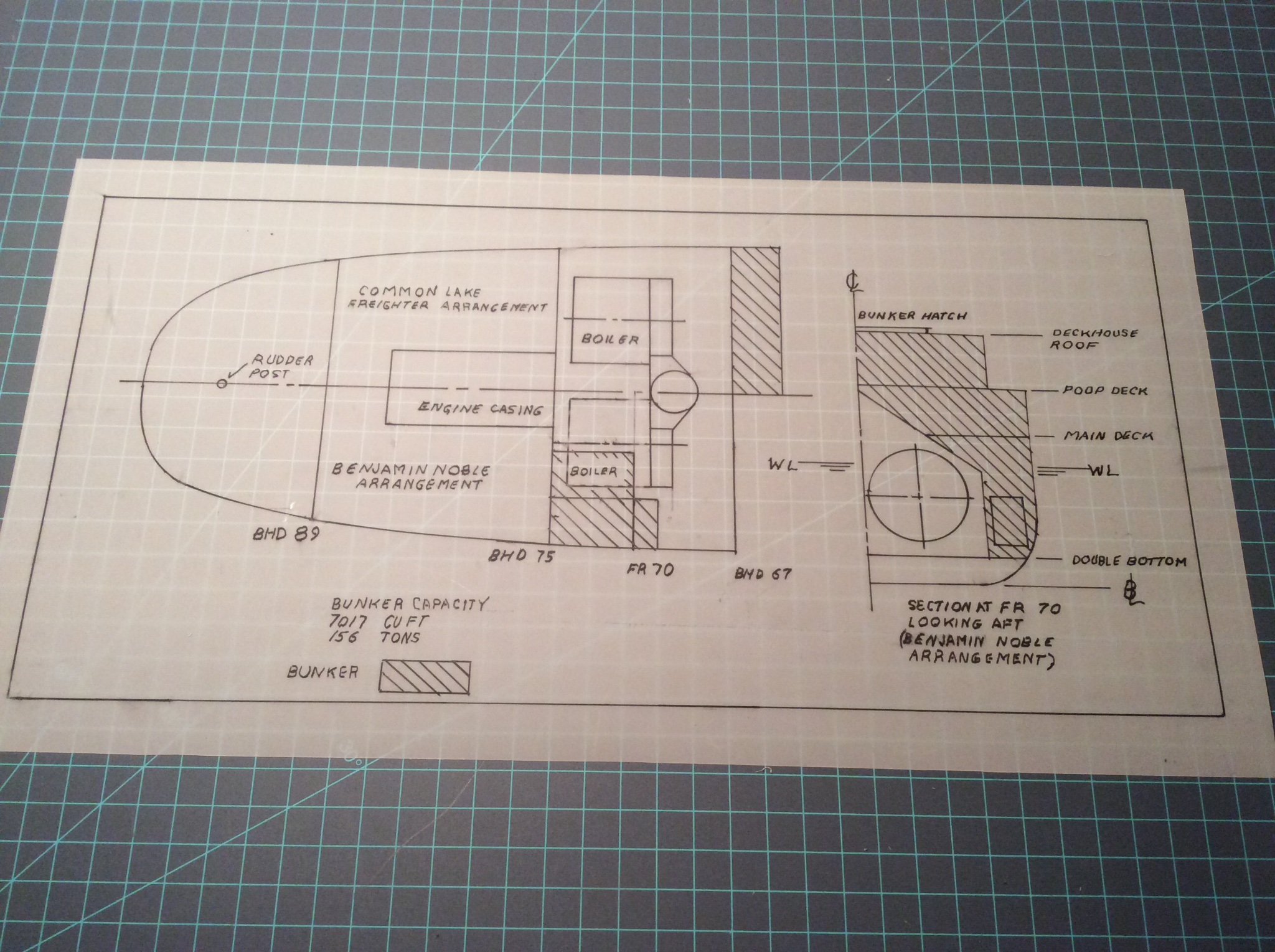
The Rabbit hole: in late July my wife and I visited a fellow model builder and NRG member and his wife who live nearby in Wisconsin. I was astonished by his collection of beautiful scratch built models, several of Lake vessels. I was intrigued by the way that he had added interest by giving viewers a peek of the ship’s machinery through an open door, hatch or skylight. Returning home, I decided to add the same feature to my Benjamin Noble model. I will show the engine room skylight open revealing the top of the triple expansion steam engine below. I also decided to show the coal bunker partially filled, visible through the open coal bunker hatch.
This all required an examination and reconstruction of the ship’s internal arrangements. I was able to do so with reasonable accuracy from the structural drawings that showed the rectangular trunk passing from the engine room to the deckhouse roof. This same drawing also showed the coal bunker and located the two boilers. I was surprised to discover that the layout of the coal bunker and boilers differed from the usual layout of Great Lakes ships- see drawing below. Instead of locating the coal bunker at the forward end of the deckhouse, the bunker wraps around the boilers with the hatch behind the smokestack.
Why did the Noble’s designers do this, and why not use the generally accepted arrangement? Answer: by doing so they increased the volume of the hold by the 7000+ cubic feet that would otherwise be taken up by the bunker. So then, why did the designers of other Great Lakes ships favor the more common arrangement that cost them hold volume?
For every cargo that can be conceivably be carried aboard ship there is what’s called a “stowage factor” that lists the volume required by one ton of cargo. The principal American Great Lakes cargo was and still is iron ore. In the early 1900’s, coal was a secondary cargo, loaded when the opportunity presented to avoid returning back up the Lakes in ballast. The stowage factor for iron ore, a very heavy cargo, is about 20 cu ft per ton. When hauling iron ore the ship would be considered to be fully loaded well before her holds were full. Sacrificing hold volume for bunker space, therefore, did not affect the carrying capacity for vessels built to haul iron ore.
Why did the Noble’s designers need the extra hold space gained by her unusual and costly bunker arrangement. She was designed to carry a very light cargo: pulpwood with a stowage factor of over 140 cubic feet per ton. When she sank, she was carrying railroad rails, stowage factor 12 cubic feet per ton. There was a lot of empty space in her hold that was subject to flooding if her hatches failed.
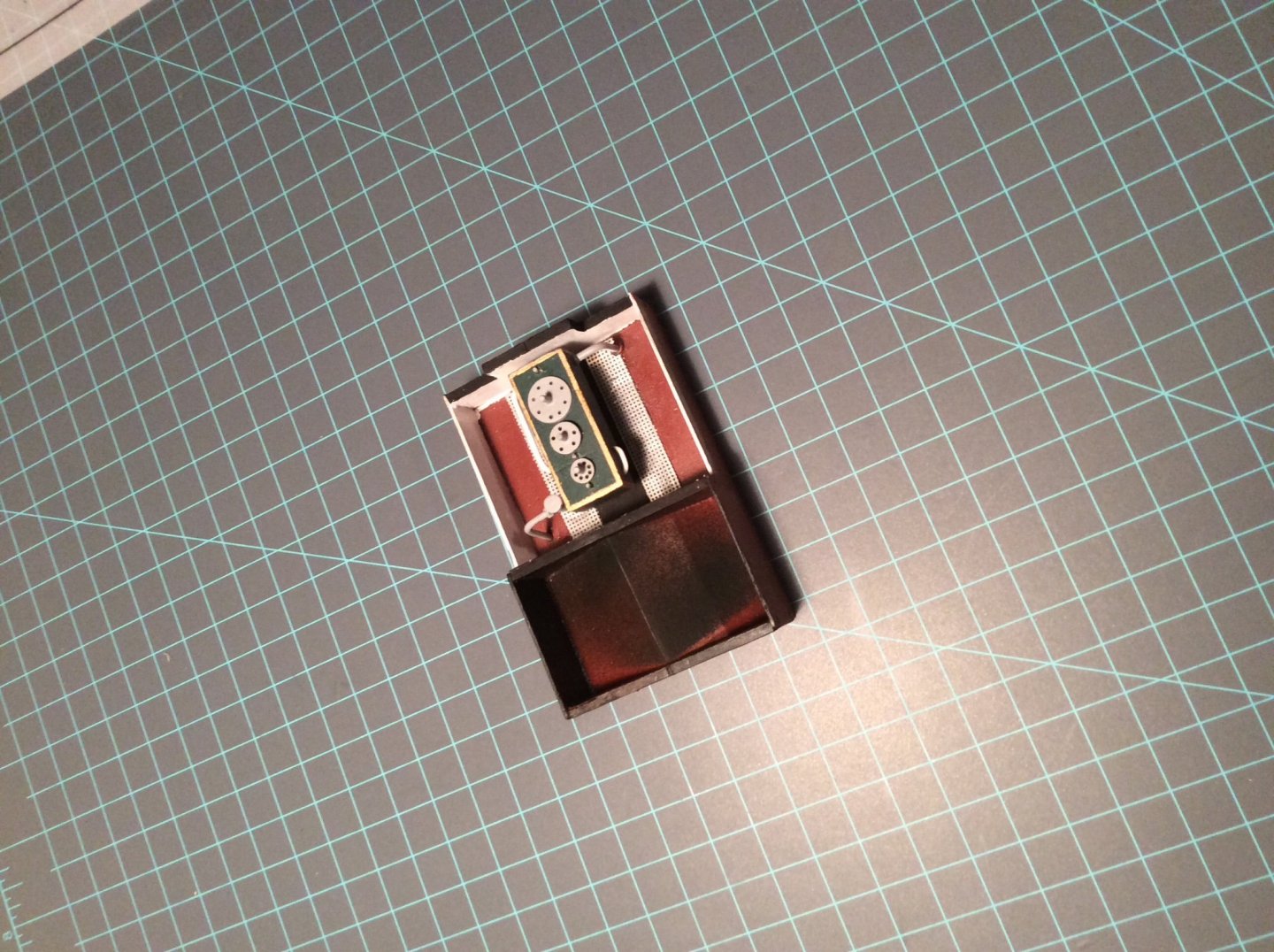
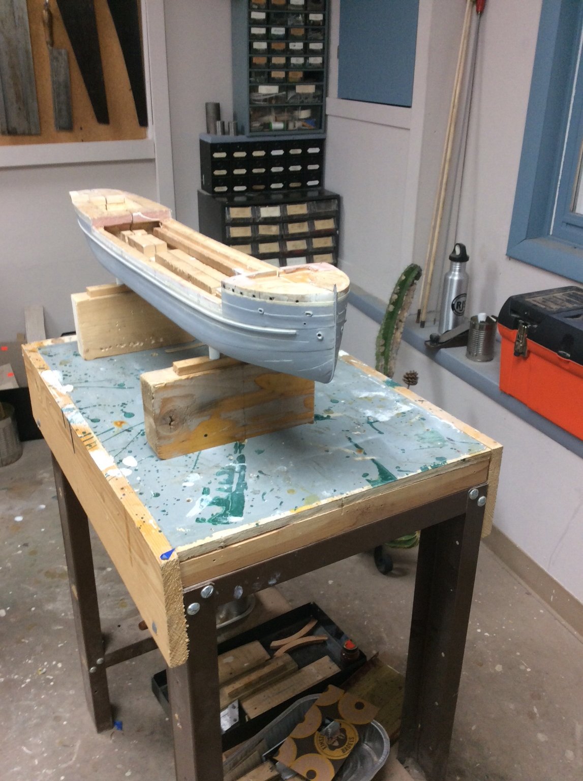
The subassembly in the second photo below fits into a space chiseled into the poop deck. Parts of it will be visible through the engine room skylight. The other part is the coal bunker. The two boilers would have been underneath.

-
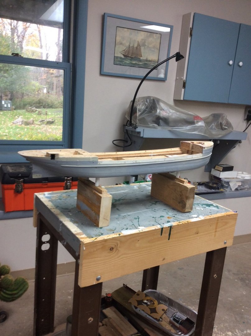
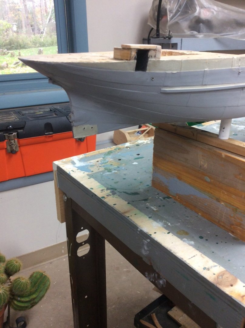
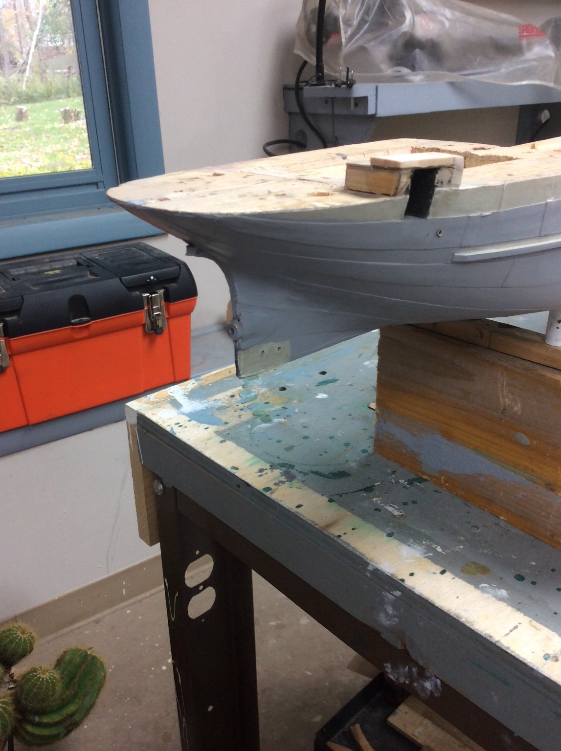
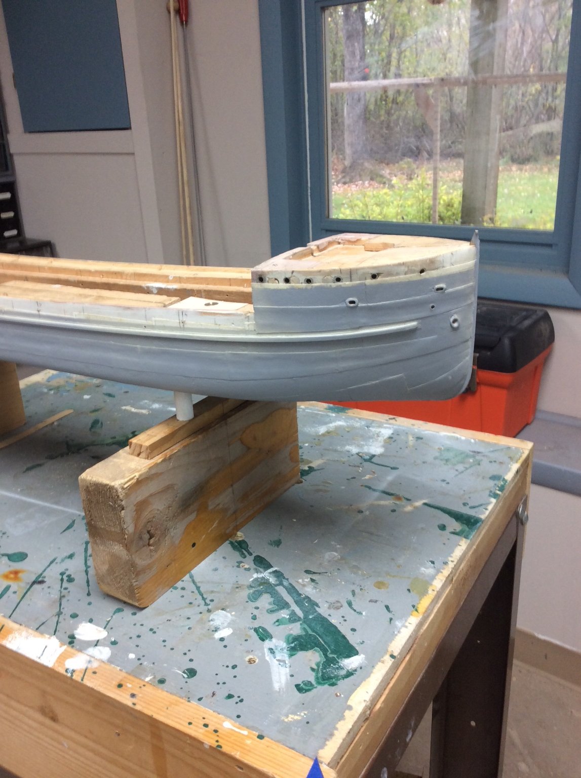
CHAPTER 8- A Major Milestone and a Rabbit Hole
Since my last progress report almost three months ago, I have been working steadily on the model. A couple of weeks ago, I reached a major milestone, I fastened the two hull halves together. Before I could do this, I spent considerable time adding necessary hull openings; hawse pipes, mooring pipes, porthole linings, the propeller shaft tube, and piping inlets and outlets. Once the halves were fastened, I added the keel plating and the propeller boss reinforcement plates. The final keel plate aft awaits installation of the lower rudder support shoe, that first requires installation of the rudder and propeller. The White supports utilize the female threads embedded in the bottom of the hull but the supports themselves are temporary. The grey color is primer. As usual, the digital camera shows areas that need to be cleaned up.


- Keith Black, lmagna, wefalck and 16 others
-
19


A Formular for wind pressure and other sailing related calculations
in Masting, rigging and sails
Posted
There is a huge difference between science, academic engineering, and practical engineering. For example, science describes the behavior of materials under tensile loads, academic engineering might teach advanced analysis methods for determining the strength of wires twisted together and the practical engineer who will understand the theory describing the strength of wire rope, selects the actual wire rope to be used from a manufacture’s catalog.
The amount of high end analysis performed also depends on the application. A Naval Architect designing a mass produced day sailer can avoid expensive engineering analysis by over designing, as the slight loss in performance is less likely to be as important as the final cost of the boat. On the other hand, when designing an America’s Cup Yacht, budgets usually include state-of-the-art engineering analysis as performance is all important.
Loading on sails is completely dependent on rig. The square rig is intended for downwind or reaching performance so loading is mostly direct impingement of wind on the sail cloth. The sail fails when the fabric tears; The sail blows out. Modern sailboat rigs are designed for optimal upwind performance. In this case the sail acts as an airfoil and eventually the sail cloth stretches to the point where the sail loses its shape and must be replaced. That’s why sails on new high performance racing yachts are often black. The cloth fibers are Kevlar.
Roger