Roger Pellett
-
Posts
4,519 -
Joined
-
Last visited
Content Type
Profiles
Forums
Gallery
Events
Posts posted by Roger Pellett
-
-
CHAPTER 8- A Major Milestone and a Rabbit Hole
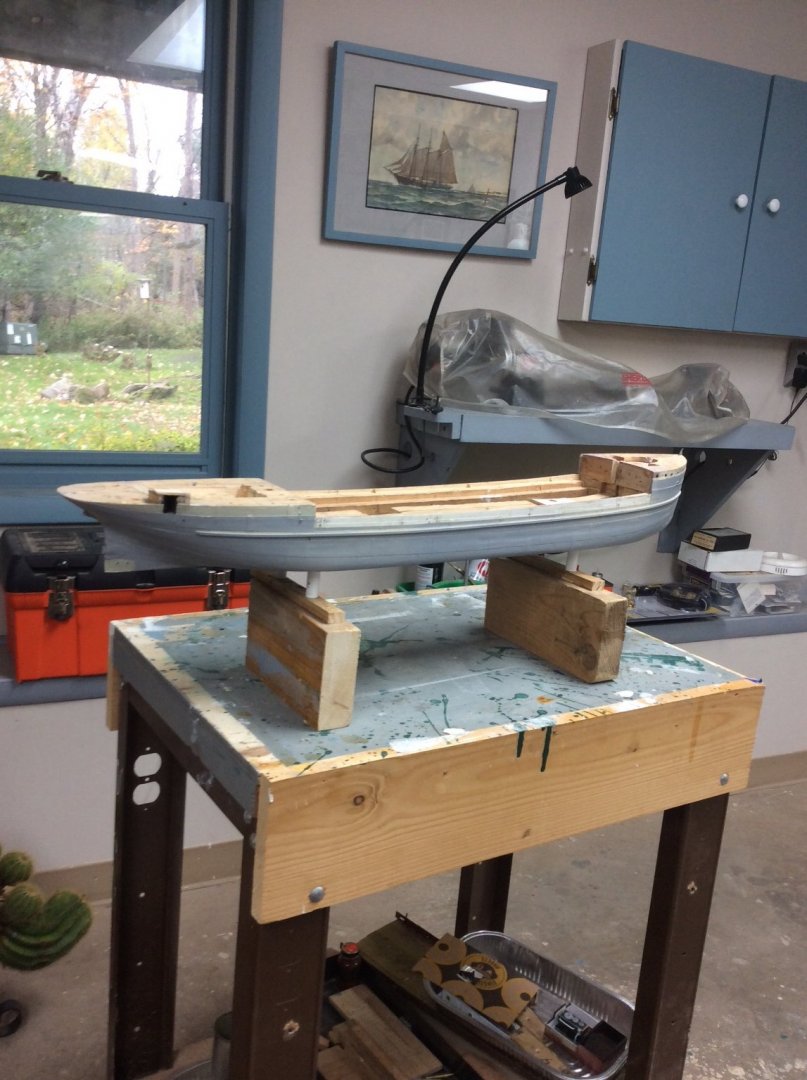
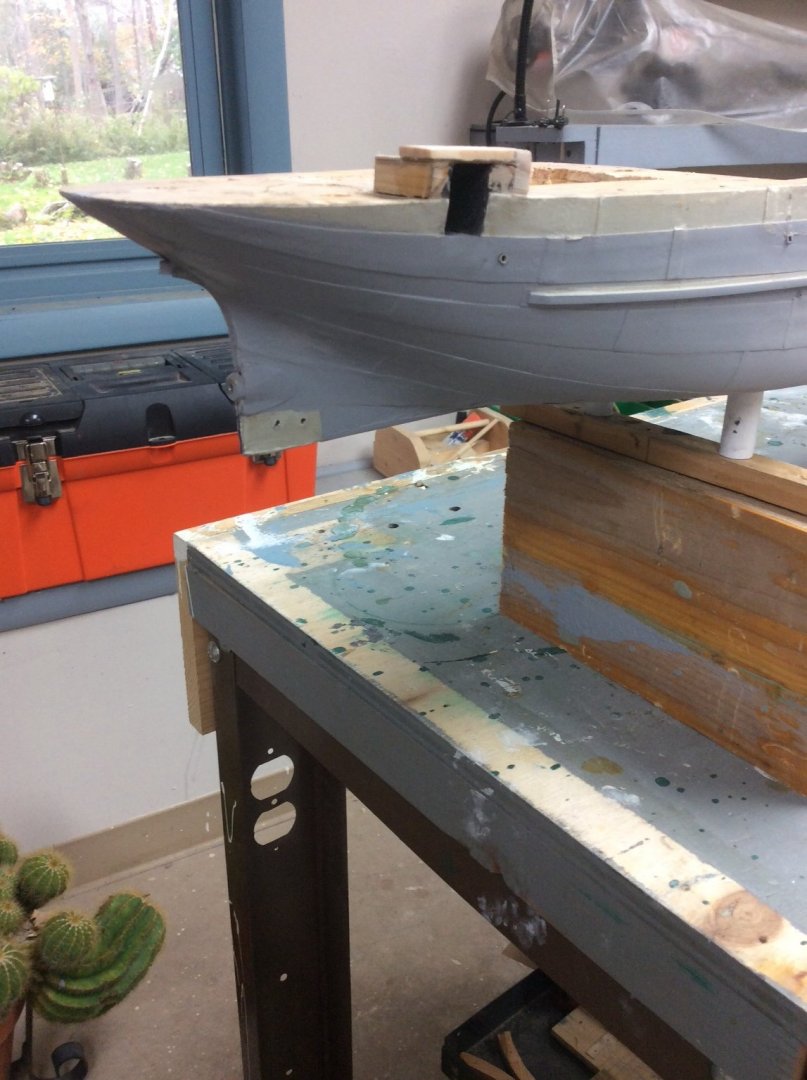
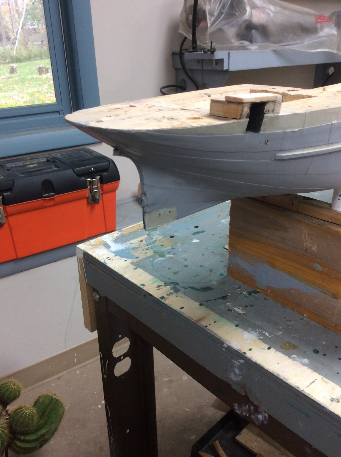
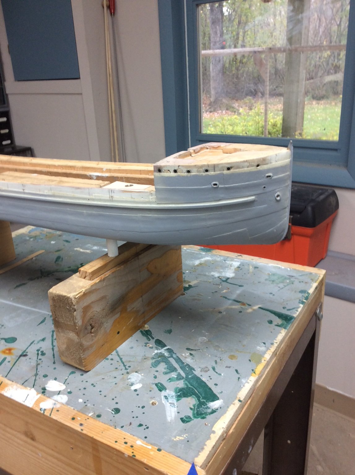
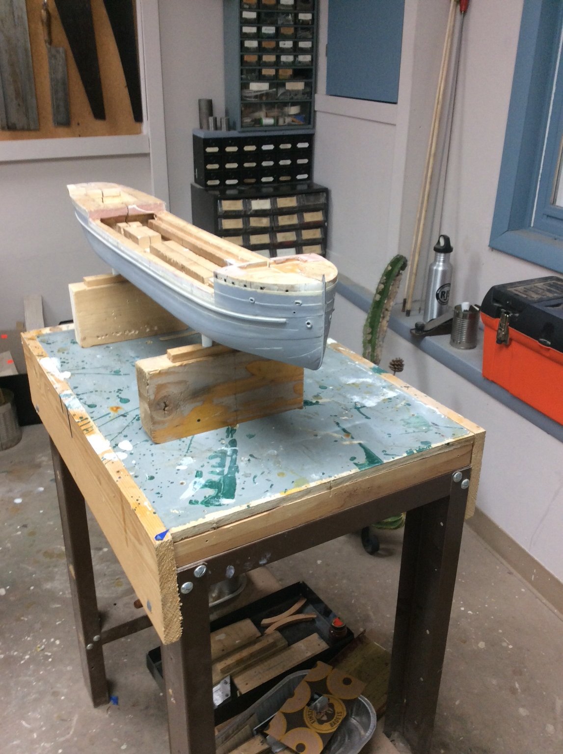
Since my last progress report almost three months ago, I have been working steadily on the model. A couple of weeks ago, I reached a major milestone, I fastened the two hull halves together. Before I could do this, I spent considerable time adding necessary hull openings; hawse pipes, mooring pipes, porthole linings, the propeller shaft tube, and piping inlets and outlets. Once the halves were fastened, I added the keel plating and the propeller boss reinforcement plates. The final keel plate aft awaits installation of the lower rudder support shoe, that first requires installation of the rudder and propeller. The White supports utilize the female threads embedded in the bottom of the hull but the supports themselves are temporary. The grey color is primer. As usual, the digital camera shows areas that need to be cleaned up.


- BANYAN, gieb8688, Harvey Golden and 16 others
-
 19
19
-
Yeah,
Osprey books seem to be an example of “too much of a good thing.” I started buying them many years ago to use their color plates for painting model soldiers. They have now expanded to cover campaigns, military hardware, tactics, and now ships. I have been unimpressed with those books dealing with maritime subjects.
Roger
- Keith Black, mbp521, Canute and 2 others
-
5
-
Valeriy,
They will just be imitation gears- deck winches, cargo winches, and gears for turning vowel ventilators.
That guy’s fixture is really clever. I have a large heavy gauge aluminum angle. I’m going to use it to make a knurling fixture that mounts on the cross slide of my lathe; similar to the one shown in the Sherline catalog.
- dj.bobo, lmagna, popeye the sailor and 3 others
-
6
-
Thanks Valerie,
The project that I am working on will require a lot of gears. I just bought a pair of knurling cutters on eBay. Now I need to build a fixture to hold them.
Roger
-
-
In his excellent book, Hand, Reef, and Steer, Tom Cunliffe discusses Flax sails and provides instructions for tanning them as Wefalk mentions. He also explains in his droll manner, that waterfront rats consider flax sails to be an important part of their diet so precautions need to be taken to protect them. (The sails, not the rats!)
Roger
-
Very nice work, Rod. She really looks like a steel hulled ship. I particularly like the bottom paint color.
Roger
- Old Collingwood and Canute
-
2
-
Paul,
You’re model is shaping up to be a beauty!
Roger
- Dick Fetter and FriedClams
-
2
-
Our men’s book club read Pillars of the Earth several years ago and we all enjoyed it. I remarked that the author cleverly bookended two major events in English history. Our resident English history expert, a retired English teacher, disputed my analysis, saying that the ending had nothing to do with historical fact. As the debate raged on, he finally said, “Oh, I watched the movie!”
Roger
- mtaylor, Cathead, Keith Black and 1 other
-
4
-
Eric,
I have been making steady progress but have been waiting for something newsworthy to show. I should have a post in the next couple of days.
Roger
- FriedClams, Canute, JKC27 and 4 others
-
7
-
Your drawing shows three views: plan view, longitudinal profile, and body plan- sufficient to define the shape of the hull.
Hard chine hull forms lend themselves to the POB style of construction described by Richard above. In this case, it would appear that the hull was built with “developable” shapes to allow the use of large panels of flat steel plate. You can imitate this same form of construction with thin model-makers plywood that is readily available.
If you decide to carve the hull from a solid, I would use common lumberyard pine. It’s harder than basswood so will better hold crisp edges. Lumberyard lumber is usually designated SPF: spruce, pine, fir. You want pine. Spruce is the lightest of the three and has a distinctive and to me objectionable smell. Pine has a finer grain than either spruce or fir. You may also find a higher grade pine intended for trim work. Here in the Midwest, at least one store is stocking Monterey Pine imported from New Zealand. I don’t understand the logistics but it’s nice stuff. Balsa is much too soft, and basswood marginal. Finding the right piece of wood is part of the fun of scratch building; like a scavenger hunt!
You can make life easier by carving two half models to be joined once shaped. I drill matching holes for dowel alignment pins before shaping the hull while the two half hull sections are still square. If you have access to a bandsaw, start by cutting the longitudinal profile with the half hull block laying flat on what will be the finished model’s centerline. Next, fasten each half hull section to something so that the finished model’s centerline is vertical. A piece of aluminum angle works well for this. Now back to the bandsaw to cut the plan view shape.
You now should have two wood blocks with the plan view and longitudinal profile view shaped. Now using the longitudinal profile and body plan views, plot the points defining the chine along the hull block. Bend a very thin strip of wood connecting these points and mark out the chine. Using regular woodworking tools, carve the deadrise- the angle that the bottom makes with the sides. Use templates traced from the body plan to guide you. The Mark 1 eyeball is also an excellent tool for finding humps and flat spots in the carved hull. Do as much work as possible before gluing the two half hulls together.
Have fun!
Roger
-
Steven, very nice work!
150 or so years earlier than your model but I just read a review of a book about the sinking of the “White Ship,” a disaster that killed the heir to the English throne and over 300 of his courtiers. This resulted in a Civil was between two half siblings, Stephen and Miltilda that lasted until the reign of Henry II. It looks interesting.
Roger
- mtaylor and Keith Black
-
2
-
My models get built in the shower, while I am drifting off to sleep and while sitting in a comfortable chair waiting for my wife to decide whether the 18th pair of black pants she is trying on really fits. Talbots has the most comfortable chairs.
Seriously, this is when I figure out a new approach to remaking the part that I ruined the hour or day before. The worst thing that you can do when you mess up is to keep working to Force a Solution. Much better to stop working, clean up your bench, and start fresh another day after having time to think things through.
Roger
- Bob Cleek, Clark Griswold, BenD and 9 others
-
12
-
If you want to glue brass parts together instead of soldering JB weld epoxy sells a product for gluing metals together that dries dark grey. It works well on brass and copper. I sand the parts first to get rid of oxide and to the mating surfaces some “tooth”. You can find it at any hardware store.
Roger
- michael mott, mtaylor and Canute
-
3
-
This assumes that you intend to build your Mayflower kit instead of first trying something simpler.
There are two Mayflowers, the one that brought the Pilgrims to the New World and the replica built in England in 1957 now docked at Plymouth Plantation.
All that is known about the original vessel is her tonnage (an approximate measure of her internal volume). No pictures, drawings, etc. exist.
The replica was designed by William A. Baker, a Naval Architect employed by the shipbuilding division of Bethlehem Steel. His avocation was researching ships of the American colonial period and he enjoyed writing about his findings.
I would assume that your kit builds a model of Baker’s replica. There are at least two books written by Baker describing his design and the process that he used to design her. These books can be found on used book sites. They will also include Baker’s plans for the ship. Either would be a great supplement to the kit information.
Roger
- mtaylor, Keith Black and Baker
-
3
-
Nobody building a ship model duplicates the exact same materials used to build the actual ship. We substitute brass for wrought iron and we substitute different species of wood. In that sense, we all cheat. On the other hand, many kit manufacturers do not use high quality or even appropriate materials in their kits. So, if your substitution produces a better model, go for it.
Serious, model builders scratch building unique models are usually concerned about longevity. The standards that Jaager references above limit materials to those that will provide long lifetimes for models meeting their requirements. This is of particular concern if your model will be sold to others.
Roger
- mtaylor, Keith Black, Canute and 1 other
-
4
-
Jaager,
I certainly agree that close is good enough. Especially in the day when painters mixed their own paints. Eric also makes the point that these oxide paints were especially subject to variation because the natural pigments varied.
I have never tried to use a color wheel. For my last model, I mixed artist’s acrylic pigments by eye.
Bob,
My reason for posting this was to encourage more modelers to push their limits a little; away from premixed paints. This is an alternative.
I have found that quality artist acrylics in tubes mix up and spray well. For my last model, though, I bought a huge tube of yellow ochre at WallMart for something less than $5. The grains of pigment could have been used for aggregate to pave your driveway.
Actually, I found an unopened bottle of Floquil SantaFe orange in my stash. I think a slight red tint and Eric Ronnberg’s system of adding grey to mute the intensity should do the trick.
Roger
- Chuck Seiler, Bob Cleek, Canute and 1 other
-
4
-
I have been thinking ahead to painting my Benjamin Noble Lake Freighter Model. She was launched in 1909 and I want to accurately duplicate the industrial colors used back then, among which is the red lead paint commonly used as bottom paint on the Lakes.
My first stop was Eric Ronnberg’s great article from the Nautical Research Journal about Nineteenth and Early Twentieth Century paint colors. This article used to be included in the Resource section of the Guild’s Web Site. For reasons utterly beyond me it is no longer there. Fortunately it can be found in Volume 2 of the Guild’s Shop Notes. In addition to including color chips, the article discusses muting colors for different modeling scales.
The article, however, does not include formulae for mixing the colors represented by the paint chips, but after rereading the article I discovered that each paint chip is identified by two codes. Each code representing a different color standard, one of which is the Munsell standard. Each Munsell code represents a different unique paint color. This means that if you know the Munsell number for a particular color, someone should know how to mix it.
So, I typed in the Munsell number that Eric provided for his red lead color chip into my Internet search engine, and sure enough, up popped several sites for red lead color. At least one, was a company that offered to duplicate it (lead free.) The service is not cheap. There is a $25.00 fixed charge plus the cost of the paint.
Another possibility would be to see if commercial paint retailers can match Munsell Numbers. Some of the lacquer based auto body paints might be suitable.
Roger
-
-
Brian,
Civil War Navy Ships Boats usually had a “wash strake” fitted above the regular planking. The wash strakes were pierced with openings that served as rowlocks for the oars. This construction is shown on two of the pictures that you have posted. To be exact, the rowlocks were often “composition” metal; the term then used for brass or bronze, castings. These castings were grooved and segments of the wash strake fitted into the grooves.
Roger
-
Beautiful work, Allan. There seems to be enough variety in the original Dockyard style models that yours can be finished when you say it is.
Roger
- Keith Black, allanyed and mtaylor
-
3
-
Good to see someone else from Minnesota joining up.
Roger
- AlexMN, Ryland Craze, mtaylor and 1 other
-
4
-
Industrial metal fabricators have long been faced with the problem of painting metal with a durable coating. Industrial painting specifications invariably require using a solvent to remove grease, oil, etc. This is followed by abrasive blast cleaning with sand or if possible metal grit. Most specifications then require prime coating within the same 8 hour shift.
So what does this have to do with the question at hand?
The principals are the same. First, go over the surface with a file to get rid of solder, scale, etc. A file or sandpaper will also give the surface what is known as “tooth.” Coatings do not stick to polished surfaces. Thoroughly clean the surface. An aggressive solvent is necessary. I use a little lacquer thinner in a tuna fish can. Handle the part with tweezers. Oil from your skin will inhibit bonding. Blacken or paint immediately. An invisible oxide film can form overnight.
These small parts will usually be handled after coating. To avoid damage, I seal the coating by spraying the part with a matt lacquer. Dulcote or similar.
Roger
-
My objective when I build a model is to make everything myself except cordage and chain. I have seven scratch built models and one in process. So far I have met my objective. Foe me figuring out how how to make something new is half the fun.
Roger
- mtaylor, Louie da fly, barkeater and 2 others
-
5


SS Benjamin Noble by Roger Pellett - 1:96 - Great Lakes Freighter
in - Build logs for subjects built 1901 - Present Day
Posted
CHAPTER 8 (continued)
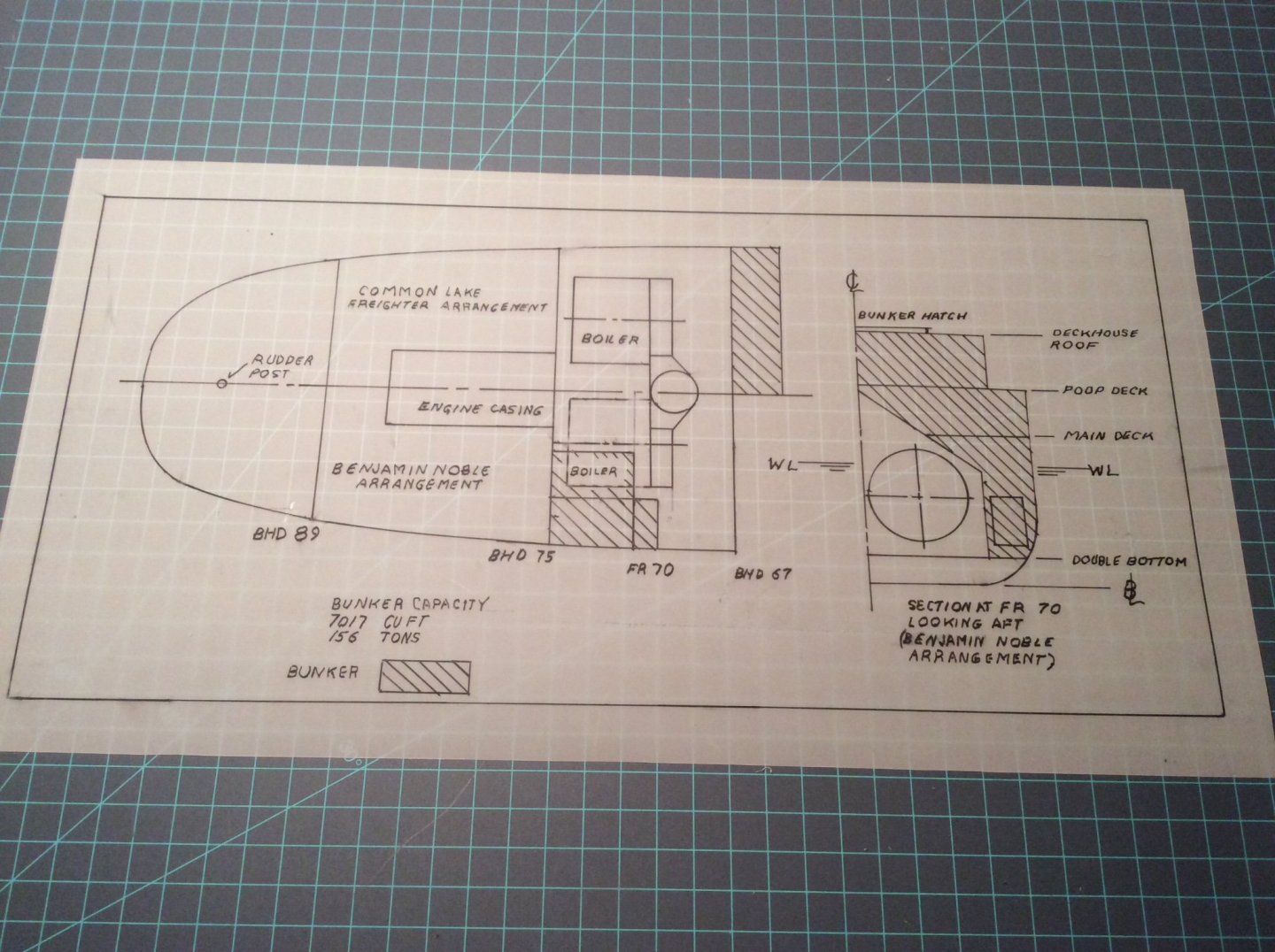
The Rabbit hole: in late July my wife and I visited a fellow model builder and NRG member and his wife who live nearby in Wisconsin. I was astonished by his collection of beautiful scratch built models, several of Lake vessels. I was intrigued by the way that he had added interest by giving viewers a peek of the ship’s machinery through an open door, hatch or skylight. Returning home, I decided to add the same feature to my Benjamin Noble model. I will show the engine room skylight open revealing the top of the triple expansion steam engine below. I also decided to show the coal bunker partially filled, visible through the open coal bunker hatch.
This all required an examination and reconstruction of the ship’s internal arrangements. I was able to do so with reasonable accuracy from the structural drawings that showed the rectangular trunk passing from the engine room to the deckhouse roof. This same drawing also showed the coal bunker and located the two boilers. I was surprised to discover that the layout of the coal bunker and boilers differed from the usual layout of Great Lakes ships- see drawing below. Instead of locating the coal bunker at the forward end of the deckhouse, the bunker wraps around the boilers with the hatch behind the smokestack.
Why did the Noble’s designers do this, and why not use the generally accepted arrangement? Answer: by doing so they increased the volume of the hold by the 7000+ cubic feet that would otherwise be taken up by the bunker. So then, why did the designers of other Great Lakes ships favor the more common arrangement that cost them hold volume?
For every cargo that can be conceivably be carried aboard ship there is what’s called a “stowage factor” that lists the volume required by one ton of cargo. The principal American Great Lakes cargo was and still is iron ore. In the early 1900’s, coal was a secondary cargo, loaded when the opportunity presented to avoid returning back up the Lakes in ballast. The stowage factor for iron ore, a very heavy cargo, is about 20 cu ft per ton. When hauling iron ore the ship would be considered to be fully loaded well before her holds were full. Sacrificing hold volume for bunker space, therefore, did not affect the carrying capacity for vessels built to haul iron ore.
Why did the Noble’s designers need the extra hold space gained by her unusual and costly bunker arrangement. She was designed to carry a very light cargo: pulpwood with a stowage factor of over 140 cubic feet per ton. When she sank, she was carrying railroad rails, stowage factor 12 cubic feet per ton. There was a lot of empty space in her hold that was subject to flooding if her hatches failed.
The subassembly in the second photo below fits into a space chiseled into the poop deck. Parts of it will be visible through the engine room skylight. The other part is the coal bunker. The two boilers would have been underneath.