
Chuck
-
Posts
9,455 -
Joined
-
Last visited
Content Type
Profiles
Forums
Gallery
Events
Posts posted by Chuck
-
-
Im not sure I understand the question. The uprights are straight up and down....no angles. They are not square to the keel per say because the keel isnt straight. The keel is bent up at the stern which is a typical feature with a rockered keel. So to better explain....they are all parallel to the bulkheads and straight up and down. That is an easier reference. Just follow the plan. As you can see....they will be perfectly straight and even with each bulkhead and even the edge of the paper for the plan.
-
Good question....Its mid ship. So dont measure up from there to find the height of the port sill. You would be best to measure 1/8" up from your bulkhead (top of deck after planking) and that will be the top of the deck. The false deck is 1/16" and then teh planking is another 1/16" even though I will go with a slightly thinner plank.
The top of the port sills is 1/2" from the top of the bulkhead (deck at side). So if your batten doesnt lay across your bulkheads smoothly, it probably means one bulkhead is too high or to low. Especially after you measure that distance up from the top of the bulkhead to the sill. The top of the bulkheads will be faired later so basically.....dont over analize it. Just run the port sill batten so its smooth. Then check that the deck (Top of bulkheads) will be 1/2" below that. If not....the top of the bulkhead for the deck will need to be either sanded down or built up slightly.
Chuck
-
Medium CA.......Just a drop on each bulkhead. I only glued two at a time and worked my way across the hull.
Chuck
-
-
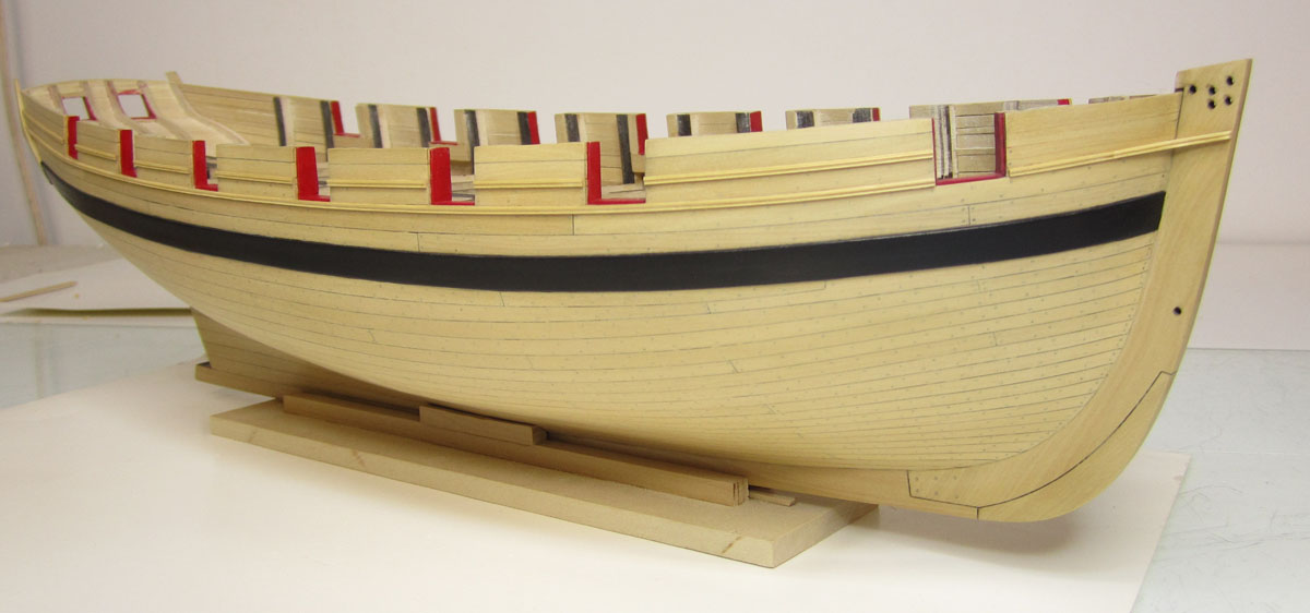
Yupp it was included. Just like the original draft I posted. But I knew they were all 3/16" planks at the center of the hull so it wouldnt effect that. So adding them before lining out made it easier to visualize the eight remaining planks in the first belt.
-
Everything below the wale, I did include the garboard......... I actually have a second planking draft that is slightly different and shows 21....this one is just more clear to post, not to confuse the situation. There are also two deck plans. All original but with slight differences. The important thing to note however is that they are identical in showing no steelers and the one drop plank.
When I started planking, I had two versions of my own plans ready to go....I found that after doing the math, the 20 strake scheme was a perfect match to fit 3/16" wide planks mid ship in two belts. Once the hull was lined off and I divided into two belts, below. Each ten plank belt divided up into perfect 3/16" wide strakes at the center bulkhead.
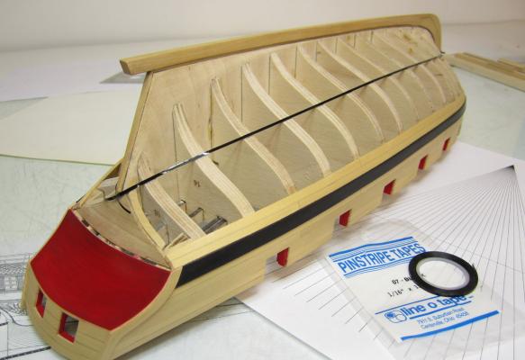

The break at the square tuck divided the hull perfectly with ten strakes in each belt. Whereas the one that showed 21 strakes would need a funky smaller fraction. Its a lot easier to rip 3/16" wide planks and its a standard wood thickness to buy, so I went with that one.
As a side note....I added the drop plank and the first two strakes in the first belt before I lined off the hull. It just made it easier to do the lining off. Thats why you can see them in the picture while I lined out the hull.
-
Jan wrote:
has nothing to do with actual "real world" planking techniques. In the real world there are no planks wide enough to allow for the amount of spiling required in his method.
Of course, Chucks models look absolutely great, but in my eyes more than perfect, where at least my - beginners - strife is for real world authenticity, I mean, whats the point of making everything above the waterline look absolutely real up to the smallest detail, while the other half the ship (the under water section) is a fiction?
Jan...Not fiction at all.
But I know folks say that steelers and drop planks are just fine and were used historically. That is true....but the huge number of them you see on model ships and explained as the proper way to do it in many books and instruction manuals and practicums. Its just a crutch. So whatever the method.....a hull that looks like this is not something I find attractive or even historically accurate. So I prefer to go for fewer and replicate the way its done on a similar contemporary model or shown in a contemporary draft from the same era. Its just my preference.
I have no intention on picking on the fellow who planked this hull below. But its extreme steelers gone wild and if this is the way he (or you) wants to go its OK. But I find many people using them and only because they find an example where one or two were used historically, and it is just a short rationalization further to go ahead and use 5 or six or even more at the bow and as many at the stern. I disagree entirely. Its just an easy fix and a crutch. I just dont think its accurate or aesthetically pleasing. This is in terms of what we were discussing earlier. I will say this. To plank the hull like this fellow did would probably take longer and be more frustrating than it would to just give lining out a hull a chance. Cutting all of those weird shapes randomly etc.
One drop plank at the bow at most...and no stealers at the stern. That is what I will always shoot for. I think its more accurate and looks better. Not that you wouldnt be able to scour the web for an example or two that is contrary to my opinion. I just think its an excuse to continue to use them willy nilly and in huge numbers rather than learn how to spile and plan a hull's planking. Again, just my opinion. And its Ok. If folks are happy with that, fine, But I just dont buy the argument that this image above is accurate in any way...even if you could find one example that might look a bit like it.
I would rather not get into a lengthy debate about it either because its one of those circular debates. Its just a matter of choosing what you are willing to live with on your project...without trying to force the idea that it must be accurate because one image exists showing something maybe a little similar so...... Then they feel better about using them and wont bother trying to figure it out beyond that. I have had countless discussions on the matter actually. Its more complex than this because it depends on the country of origin, the year, the shape of the bow and hull etc. There is no one size fits all, what kind of ship......... An apple bowed whaler will certainly be planked differently than a sharper cutter or frigate built 75 years earlier and from different countries. Dutch practice vs. English practice. There is just too much to consider for a simple answer..
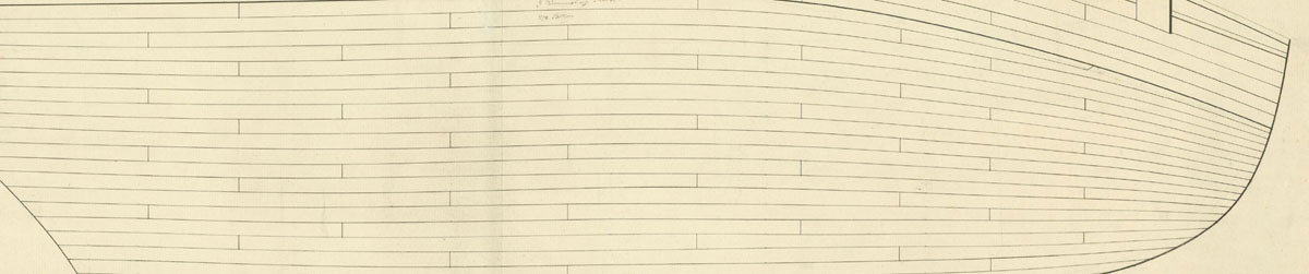
But I am so lucky because I have this below. Its the planking expansion...just a portion of it so I dont violate any copyright rules...and its for the Cheerful. So I am very comfortable saying its reasonably accurate and the actual ship was closely replicated.
 Its not fiction at all. The draft shows exactly 20 strakes below the wales. One drop plank only, no steelers. I have no idea how they would have done this in actual practice but there are plenty modeling techniques that can achieve this result. That is if its something you would have fun learning how to do.
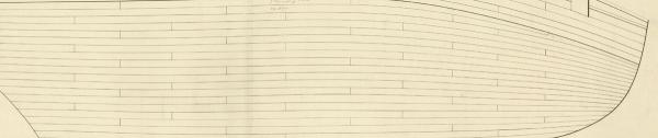
-
The Garboard is almost always in the same approximate area. Once you line off the hull you will see if you have it in the wrong place. I dont have any hard and fast rule or even know if there is one. But after lining out the hull with belts I can isolate the lower belt and its not that hard to determine how many planks and if I have to move the garboard back a bit. Thats why it is so important to plan it all up front.
As far as the planking fan goes...I pretty much spell out how I line off the hull and use the planking fan in this tutorial here.
It shows everything and also describes the Tape method for finding the curve of the plank instead of the gap method I used above.
Chuck
-
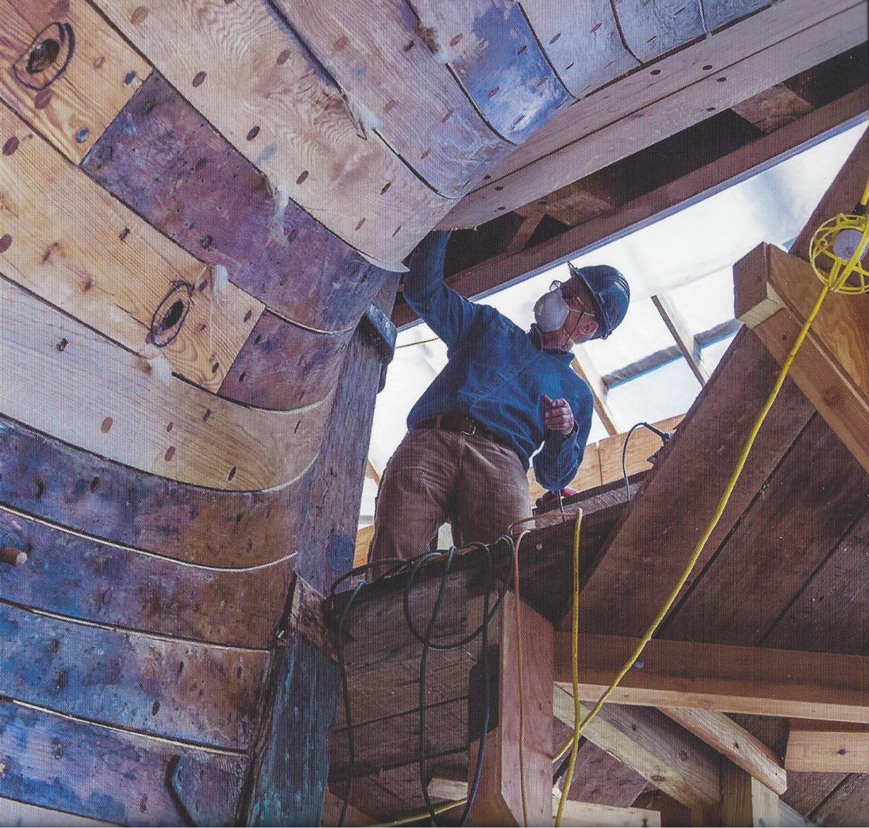
Actually not Jan...The results are pretty accurate, and its not fiction at all. Its just the method I am using is one that is for modeling. Those contemporary models are very accurate to what the ship's really looked like. What I meant was that I have no idea how the original ship builders achieved the results. Its not really important to me. Its the end results that I am trying to replicate.
Notice the crazy bending below. I am sure they started with wider planks....then they applied some crazy bending as well. but the results are the same....no crazy pie-shaped steelers.

Chuck
-
-
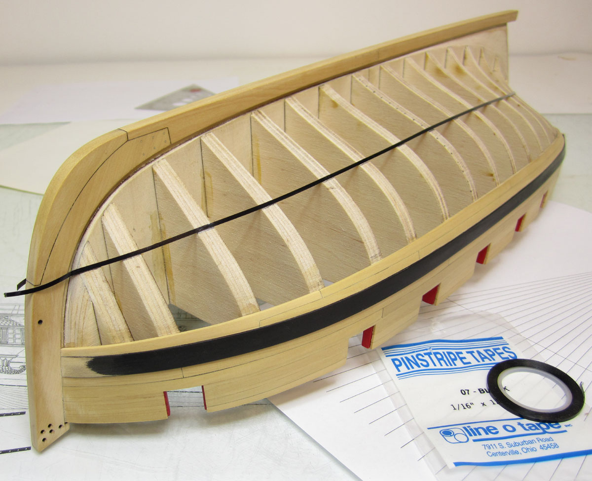
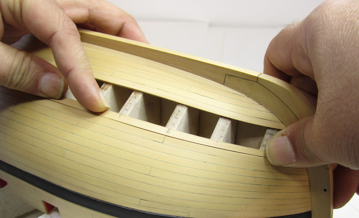
fortunately I havent had time to finish those last five strakes so I just took some pictures.
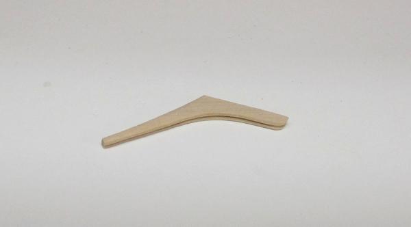
Here is a staight plank as if I were going to place it on the hull. It could be at the bow or at the stern. Most beginners would try to force this into place and the top edge of the plank would lift off the hull and not sit flush against the bulkheads. Some fight with it using pins and clamps and it gets messy. Holding it without bending like shown reveals the gap . Note the widest point of that gap.

Mark this location as the center of the gradual curve you will need.
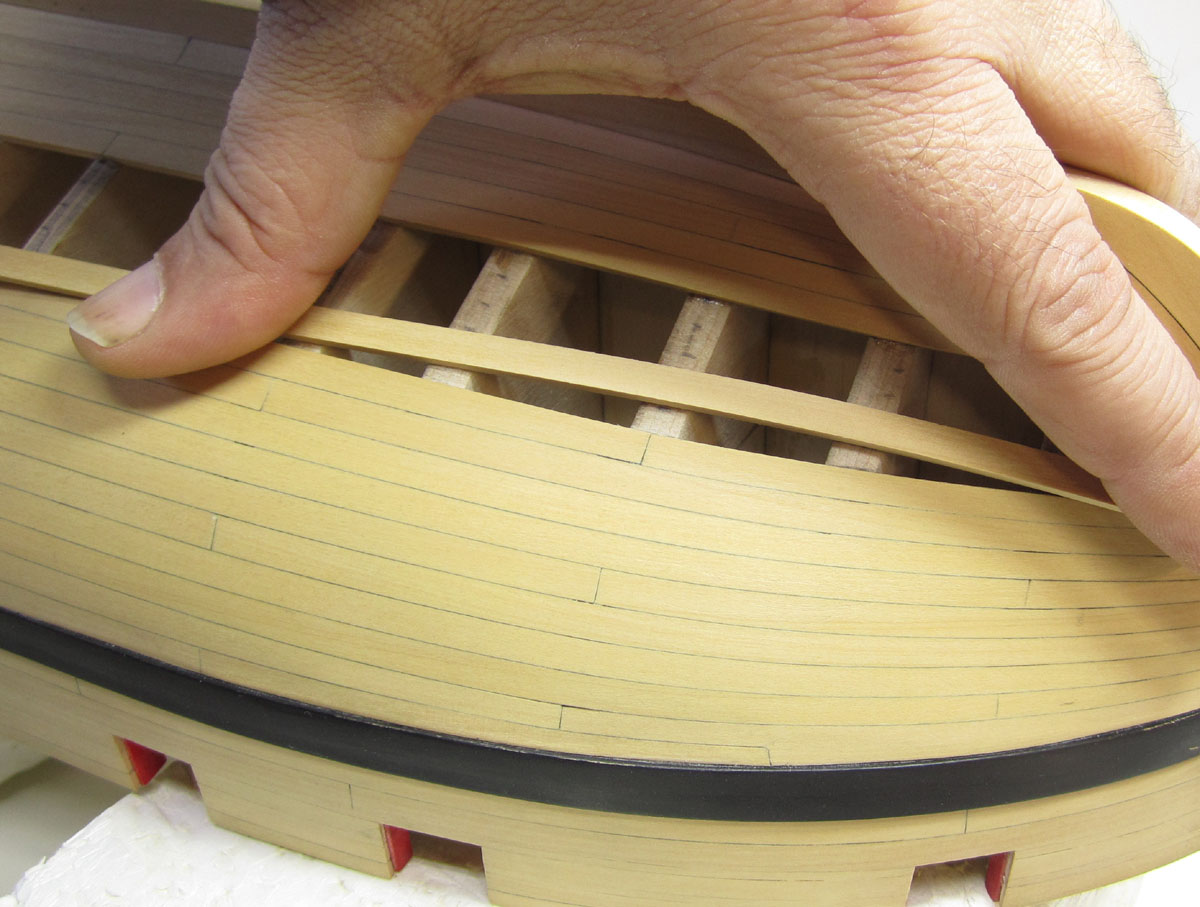
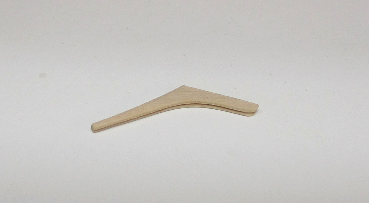
In the next picture, after bending, you can see how nice it fits and how it is flush against the bulkheads. No forcing needed. Its a perfect fit. Note the dot I marked on the plank for the apex of the curve or the widest part of the gap..You could use the compass method or the tape method to find the exact curve, but I prefer to eyeball it like this. Visually its easy to see the curve after a little practice. I always over bend slightly.

Now all I have to do is bevel it a bit and darken the seem as I did in the video and glue it on.
-
The same thing at the stern as at the bow. Basically you hold the straight plank in place without bending it. Because the one on the hull already is curved, there will be a gap between the two. You find the widest point of that gap or the apex of the curve you will need and mark its location on the new plank. That will reference the center or top of the bend you must create. I hope that makes sense. Then you bend it as I did. Bend it a bit more to allow for spring-back.
-
-
-
Its all spiling......basically instead of cutting it from a wider sheet, I am achieving the same spiled curve with bending alone. Either way would work. I did it a bit of both on the Winnie. Its all the same thing. The part you should not get stuck on is how to achieve the proper curve and shape. Either cutting it or bending it will work. The important thing to get from this is that you will require a curved and tapered plank in the end before you adhere it to your hull. Thats the important part. No force fitting will ensue. You can try and find any method to achieve that shape you find comfortable.
If you line off your hull first and have a plan, and then have your planks properly curved and shaped before you glue them into position. You are good to go. If you also start with just one drop plank at the bow (just under the wale)....you have a really good chance of making a nicely planked hull with some planning and pre shaping. Its usually what I see on contemporary models. I just try and copy that. No steelers at the stern.
Once you get past the habit of using a straight plank, all the same width, and trying to glue it onto the hull, forcing it into position, it will naturally result in a hull with fewer steelers and drop planks. It just goes a lot easier. Rather than use steelers at the stern, just use planks that gradually get wider than they are at mid ship.
The only way to try this when I was breaking my bad habits, was to plan it all out ahead of time. Copying the layouts on contemporary models.
You can use the compass method to find that correct curve, You can use the tape method to find that curve. Or you can eyeball it based on the gap as I did in the video. Once you have the curve...you could cut it from a wider sheet, or just bend it. You could heat it with a hair dryer or use one of those bending irons. You could use water or you could use ammonia. There are many methods and I have used them all. But in the end they all achieve the same pre-shaped plank before it gets glued on the hull. Having that "light bulb" moment and realizing what shape you need is the important part in my opinion.
Just to let you know, I prefer the method shown in the video. That is pretty much what I do for all my planking now. No water...just heat. Bending and not cutting it from a wider sheet.
Chuck
-
Yupp. That is pretty much how I plank a hull below the wales. If there a few planks....maybe the garboard and or the first two planks next to the garboard which are spiled and shaped from wider pieces. But thats it. The drop plank at the bow was made by using a card template first. But everything else was as I did it in that video.
-
-
Thanks Greg,
Our club has a great bunch of guys. Every month one of our members puts on a tech session on various subjects. There is really no substitute for up-close collaboration. I know we have many members here on MSW who are from New Jersey but who are not members of the local club. I think they are missing out on a great experience. I would highly recommend coming to at least one meeting just to check it out.
Next month I believe the tech session is on seizing and splicing and some rigging techniques. I am not sure.
Chuck
-
Part two was just some questions and answers. But I was a little rushed. Usually we dont have enough time to devote what is needed for the whole presentation. But here it is anyway.
I am not sure if it adds anything more to part one.....but here it is. Its hard to hear the questions being asked. Most of the conversation in the middle revolves around someone asking me about a hull with many drop planks and or stealers as described in another authors practicum...just putting them in wherever and whenever. Hopefully that will make the audio make more sense.
- Rustyj, Jack Dusty, tadheus and 29 others
-
 32
32
-
-
I said no laughing!!!!!! LOL....I cant help it, I am from New Jersey!!!!!
- Canute, Dubz, justsayrow and 6 others
-
9
-
Looking good keith!!!
One of the guys taped my planking session at my club meeting. Its freaky to see myself on a video like this. No laughing. But It shows how I taper and cut a plank to match my plan from lining out the hull. I wish the camera was behind me but I hope its still worth posting.
Chuck
- Erebus and Terror, KevinR, Dubz and 47 others
-
50
-
That looks very good, Well done. If you decide to take it apart and break anything. Let me know. I will send you the replacement parts to fix it up good.
-
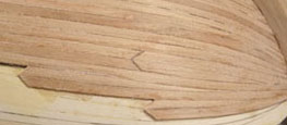
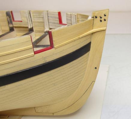
Here is a look at that "ear" piece. Actually I am not entirely sure it can be called an "ear" as it is only an extension of the molding. But this is indeed what I came up with. Taking a piece 1/16' thick I formed the piece. Its shape was found playing around with a card template. Then I transferred it to the wood. Finally the same scraper I used on the molding was used on this piece. Then a small length of molding was butt against it and continued aft. This is as far as I am going until after I plank and treenail the other side. I did however adjust some of the molding after seeing the pictures I posted yesterday. Some of it had some minor dips and waviness. I feel better now.

Then I will add the stern post and move to the inboard details by planking the bulwarks etc.

Chuck


HM Cutter Cheerful 1806 by Chuck - FINISHED - 1:48 scale - kit prototype
in - Kit build logs for subjects built from 1801 - 1850
Posted
Lou,
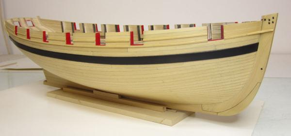
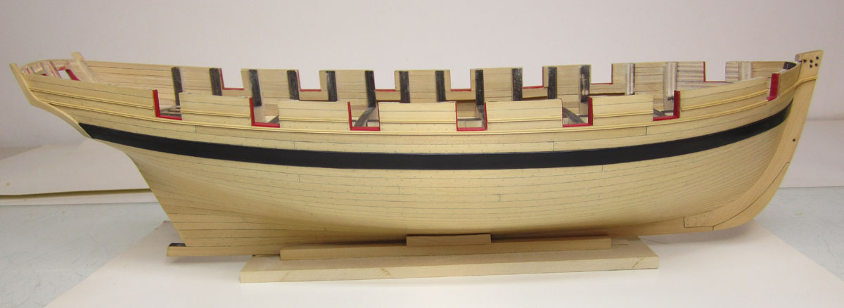
Basically I just sand the heck out of it to remove any CA that may have absorbed into the wood. Using Boxwood is also an advantage as its dense. The glue doesnt absorb very deep at all. So I am not afraid to sand the hull very smooth and thin down the planking. Typical planking is not a scale 3" thick. In fact, the topside planking above the wales on Cheerful was only 1.5" thick. Its actually noted on the planking draft. So using 1/16" thick strips is way out of scale. This is why I actually used 3/64" thick strips and then sanded them down considerably after I was done which thinned them down to about 1/32" or so. This way you get to the nice clean wood that is blemish-free.
FYI....The wales were 4" thick and the bottom planking under the wales was 2.25" thick as noted on the original planking expansion.
Chuck