
Chuck
-
Posts
9,455 -
Joined
-
Last visited
Content Type
Profiles
Forums
Gallery
Events
Posts posted by Chuck
-
-
-
-
-
Thanks John
The beauty of lining off the deck is that it allows you to create a great plan of attack. If you connect all of your tick marks you will have a really good idea of how it will look. If it needs adjustment then just sand it off and start over. You can do all of this before you lay one deck plank. Imagine if you just wing it and have half the deck planked...you are sunk. Lining off the hull first helps you avoid this.
I will do this at the stern next and then start cutting wood.

Now if you were just going with straight planks nibbed into the waterway, would you need to line off the deck like this? Maybe not. But I think it is worth the extra work. And keep in mind you want have to cut into your waterway and risk a cutting error with a bad joint while nibbing. That takes a huge amount of time and careful chisel work. So its pretty much a wash as far as the amount of time and effort goes.

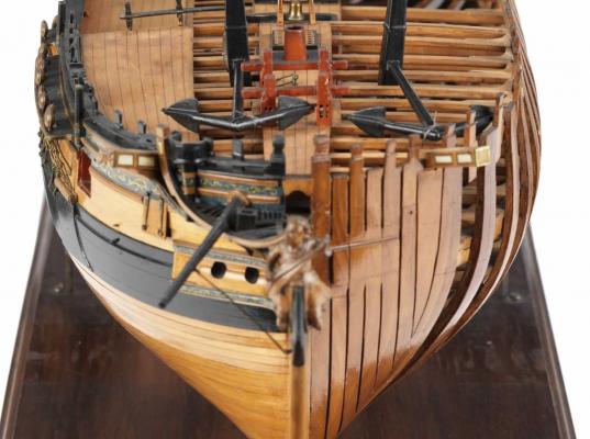
The contemorary model of a cutter shown below also has tapered and scarfed deck planks vs. nibbing. You can see the tapering very clearly here.

Chuck
-
Deck planking has started.

Just a quick note about the two styles of deck planking. There were the times when deck planking was straight and nibbed into the waterway. Most are familiar with this style. I in fact drafted the plans for Cheerful this way. However, I believe that the earlier style was still in practice at this time and probably both were used. More like a transition period. In my opinion up to possibly 1820 or even later. This second style would be where tapered and hooked scarf joints were used. No nibbing into the waterway.
I have decided to use the second style as the first is so common. You see it all the time. I find this more pleasing to look at as the planks are curved. Straight planks are to harsh in contrast with the curves all over the rest of the model. Folks can choose which method they prefer. I did use the scarfed method on the Confederacy but I simplified it with straight planks. In reality the planks would have tapered and curved a bit at the bow and stern. Like this below.
Also note the curvature of the planking on this contemporary model.
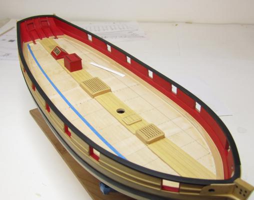
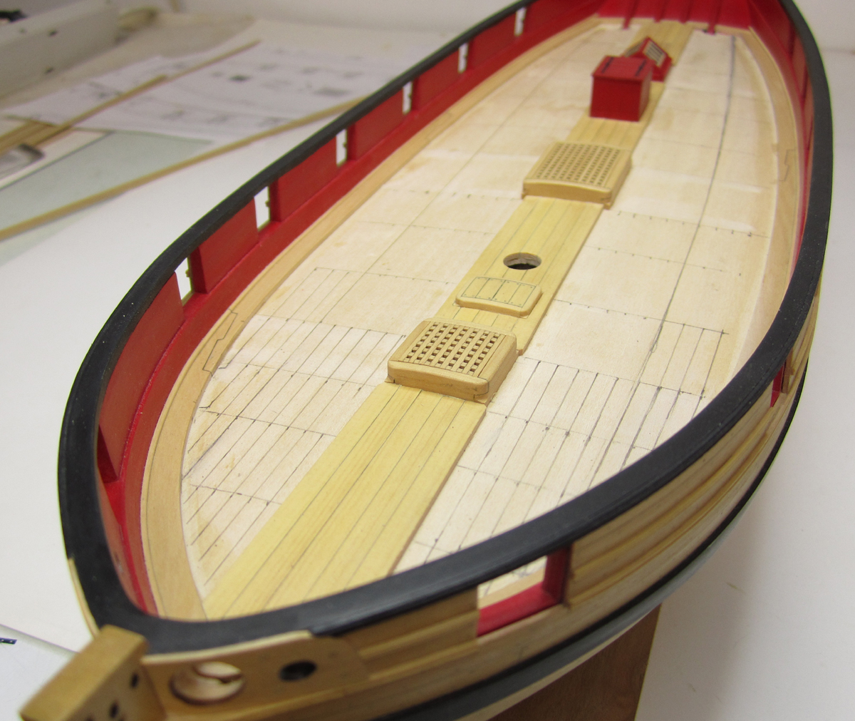
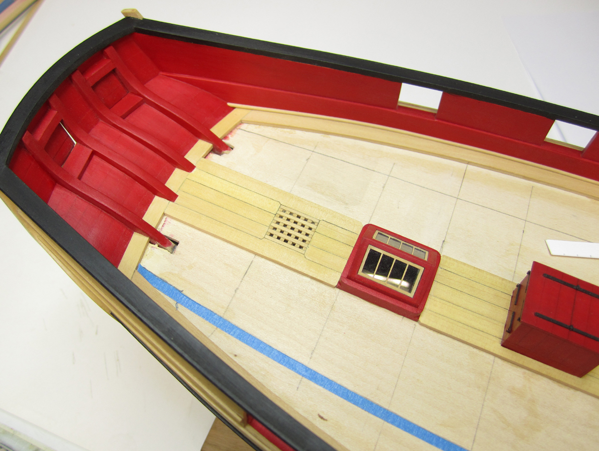
After gluing the six deck structures in position, I drew reference lines for where the deck beams would be located. This will become important later. Then I planked down the center with one strake (3/16" wide). I followed that with 2 on either side of that one. These were straight-non-tapered planks. Then I started lining off the deck much like I did for the hull planking. Although in hindsight, I should have probably tapered these 5 center planks as well. See the contemporary model image above. But they are already done, so I am moving on....
First I measured with a tick strip in 3/16" increments at the deck's widest point. The beam reference line on the forward side of the main hatch. This showed that I still have ten deck planks to put on each side.
I used blue tape in thin strips to separate the deck into two belts both port and starboard. The inner belt on each side has 6 planks....the outer has four.
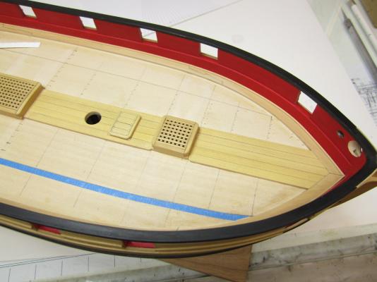
I manipulated the tape until it curved nicely from bow to stern. Remember these are not straight deck planks. The curve is not very drastic. But it has to be taped out so you can visually check the symmetry port and starboard. Once I was happy with it, I traced the inside edge of the tape to define each belt. I removed one strip of tape in the photos below. Note the curve of the blue tape still on deck.
Then, just like I did for the hull. I used my planking fan and tick strips to divide the deck up at each reference line for a deck beam. This will show me how much taper I will need in each deck plank. Its just a matter of measuring the total distance at each deck beam and transferring it to a tick strip. Then you take that tick strip to your planking fan and divide that space into six equal parts. Then you come back and transfer those ticks to your deck beam reference line.
All of the planks in this inner belt will be cut flat on the ends with no scarf joints yet. I find that on most contemporary models there are only a few scarf joints.... as opposed to modern models where the builder uses way to many. I have always seen just two or three and on the rarest of occasions four hooked scarf joints against the waterway. Most people start way too early and end up with too many of them and it looks very busy. This is also true of just plain nibbing into the waterway. In addition, by curving and tapering the planks it actually reduces the need for that many of them.

Thats it for now as I continue to use tick strips to define the width of the planks at each deck beam location. Then I will start cutting more wood.
-
I actually still have one....a Commodore 64 mint in box with plenty accessories. .....and games.
 Got it when I was 16 years old.
Chuck
- thibaultron, Nirvana, mtaylor and 1 other
-
 4
4
-
-
That is very dark. But it is also coming along well.
-
Me too!!!
-
Its not a bootlegged kit per say because there is no kit of that ship. This is the only one. But what you have there is a Chinese kit where they ripped off Ancre. They even used the Ancre plans. You can see it on the box. I remember talking with those folks at Ancre and they did not give the rights to any of these Chinese companies to use their plans. They are not even sure of the quality of the kit or if its accurately made to follow the plans the stole. Its a shame. Ancre is NOT getting any compensation for their hard work or research either. Consider this....it would be like Model shipways or Bluejacket just ordering a set of plans from Ancre and decided "screw them" lets use these to make a kit without asking for their permission. Its no different than if another kit company decided to buy a set of plans for Cheerful and just start making kits.....without asking or paying and compensation.
Its certainly a NO-GO for ModelShipWorld. We wouldnt allow a build log of this kit.
Chuck
- AnobiumPunctatum, ccoyle, GuntherMT and 3 others
-
6
-
I am re posting this from another topic so its easy for folks to find should they need it.
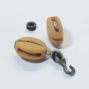
Its very difficult to measure rope using any method. That technique of wrapping it around a dowel is not very good either. There is too much variation depending on how tightly you wrap it. It would flatten out the rope and distort it. It is also hard to get a consistent space next to each revolution around the dowel. One may be closer than another. It may be squishing the wrap next to it etc. If you did it ten times or asked two different people to measure the same rope that way you would never get the same measurement. It may be close but you would be surprised.
Thankfully You would also be surprised how sophisticated our software has become. I use Corel Draw and Illustrator all of the time. When you draw a line in either program its thickness is measured in points. Lucky for us there are many conversion tables and apps that will convert points to inches.....or metric. Whichever you prefer.
If you know that a line you need is .018" and you want to see what that exact thickness or diameter in our case is....then do the conversion.
.018" is equal to 1.296 points. If you create a line in any of those programs and make it 1.296 points thick.....its pretty darn accurate. You will know what a .018 size rope should be....
Here is a chart I have on my site for folks that need a more visual way to see what these sizes actually look like.
http://www.syrenship...pesizechart.pdf
Its pretty darn on the money and I have one close by at all times when I make my rope. Its leaps and bounds the more accurate way with technology to measure rope accurately. Also set your printer for the highest quality print job........
Maybe when I get some time I will create a new chart which contains even more size variations. Maybe every .005" or something. Here is a good inches to points conversion calculator. Its the one I use.
http://www.thecalcul...s-to-inches.php
Chuck
-
Its very difficult to measure rope using any method. That technique of wrapping it around a dowel is not very good either. There is too much variation depending on how tightly you wrap it. It would flatten out the rope and distort it. It is also hard to get a consistent space next to each revolution around the dowel. One may be closer than another. It may be squishing the wrap next to it etc. If you did it ten times or asked two different people to measure the same rope that way you would never get the same measurement.
You would be surprised how sophisticated our software has become. I use Corel Draw and Illustrator all of the time. When you draw a line in either program its thickness is measured in points. Lucky for us there are many conversion tables and apps that will convert points to inches.....or metric. Whichever you prefer.
If you know that a line you need is .018" and you want to see what that exact thickness or diameter in our case is....then do the conversion.
018" is equal to 1.296 points. If you create a line in any of those programs and make it 1.296 points thick.....its pretty darn accurate. You will know what a .018 size rope should be....
Here is a chart I have on my site for folks that need a more visual way to see what these sizes actually look like.
http://www.syrenshipmodelcompany.com/resources/ropesizechart.pdf
Its pretty darn on the money and I have one close by at all times when I make my rope. Its leaps and bound the more accurate way with technology to measure rope accurately. Also set your printer for the highest quality print job........
Maybe when I get some time I will create a new chart which contains even more size variations. Maybe every .005" or something. Here is a good inches to points conversion calculator. Its the one I use.
http://www.thecalculatorsite.com/conversions/length/points-to-inches.php
I will also make this a stand alone topic so its easier for folks to find when they search for the topic.
Chuck
-
Don't forget to bring the model to our next club meeting. I want to have a good look at it. I will will be bringing mine. We can compare notes.
Since you seem to be moving right along at a rapid pace, I also completed the next chapter and its available for download. I should have another available shortly as well.
http://www.syrenshipmodelcompany.com/revenue-cutter-cheerful-1806.php
Its really looking great. The guys are going to flip over that planking job you are doing.
- mtaylor, Stuntflyer, Canute and 2 others
-
5
-
Jeff is working on updating the plans and monograph. As soon as its complete I will post an an update along with the adjusted plans on the website. There really isnt much to say about it. The scarfs just need to be turned so they are now fully visible on the top and bottom of the keel rather than the sides. Stay tuned for the actual update.
Chuck
- Saburo, AnobiumPunctatum, Canute and 2 others
-
5
-
-
-
-
I agree ken....
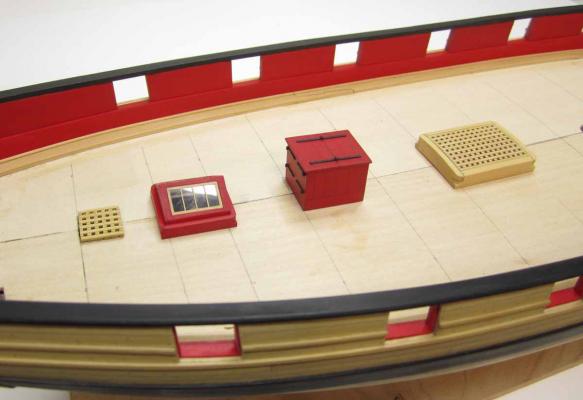
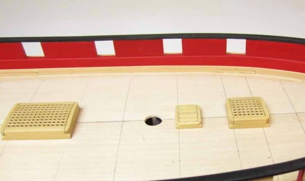
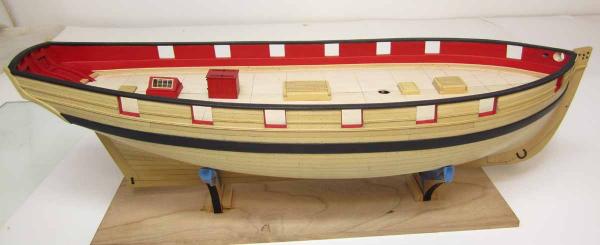
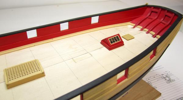
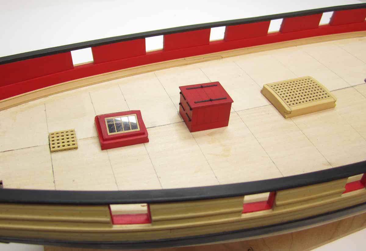
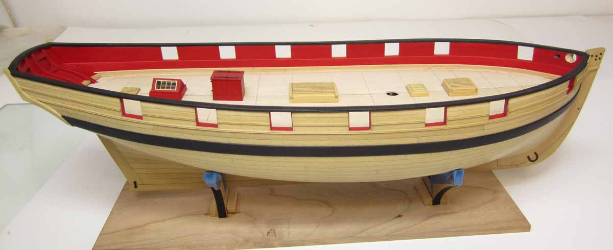
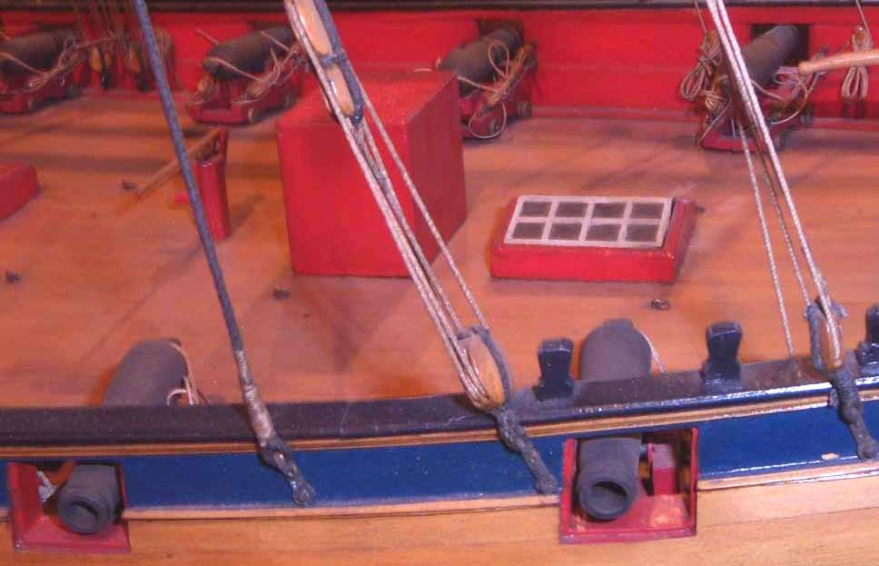
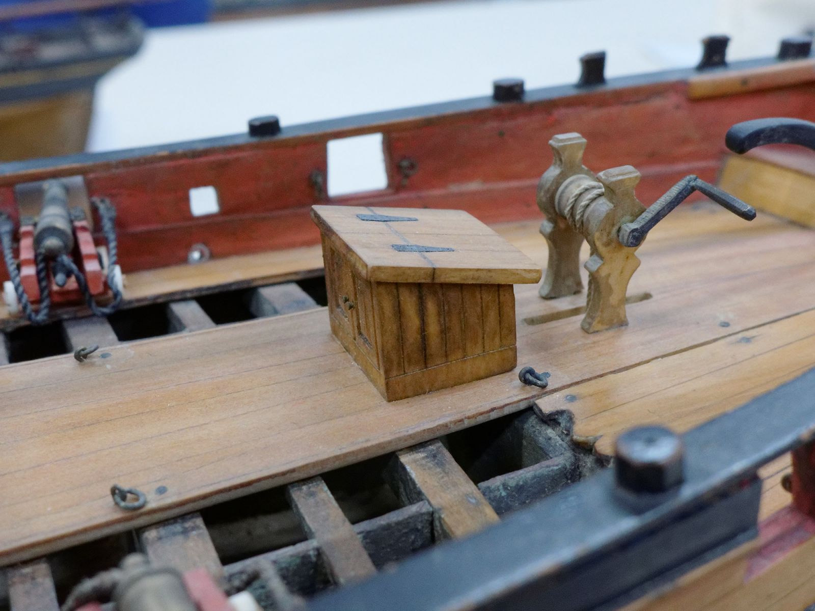
The six deck elements that I needed to complete before I started planking the deck are now finished.
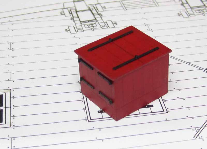
The companionway was pretty straight forward. I used 1/32" thick strips glued together edgewise to make the sides and top of the companionway. I darkened the seams before gluing them up with a pencil. I knew they would show through the transparent red paint and add a nice visual detail.
The hinges are laserboard with small lengths of tubes used to simulate them. They are not working hinges though. Each side of the companionway was built in one solid piece and assembled like a box. The hinges were glued on afterwards. I have omitted the coaming as was seen on the photo from that contemporary model.
The last deck element to complete was the coaming where the stove stack will go. That was pretty straight forward as well. I just followed the plans. The height and width for all of the coamings on these six elements varied so Careful attention was needed. I had to build this last one twice after making the coaming too high. I need to look at my plans more often!!!
Chuck

- GLakie, Elmer Cornish, UpstateNY and 31 others
-
34
-
I would absolutely change the direction of the scarf joints to what is more commonly acceptable. I looked over the plans very carefully before publishing as did others, and had made several recommendations for changes. This was actually one I had overlooked.

I will certainly make this a new recommendation to Jeff to possibly change it in the guide and plans for future printings. Nice catch. But I will talk to him and see where he is on the subject. But in my opinion, yes the scarfs should go in the other plain as is commonly seen.
Cheers,
Chuck- Saburo, WackoWolf, yamsterman and 5 others
-
8
-
I forgot to show the image of the Rogers model which was "zero" help. The companionway is basically shown as a giant solid red cube with smooth sides.
You can see the lower and flattter skylight though. This is at odds with the original draft. But I wonder why so little detail on that cube....
Chuck

-
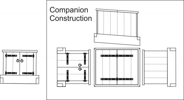
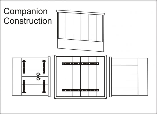
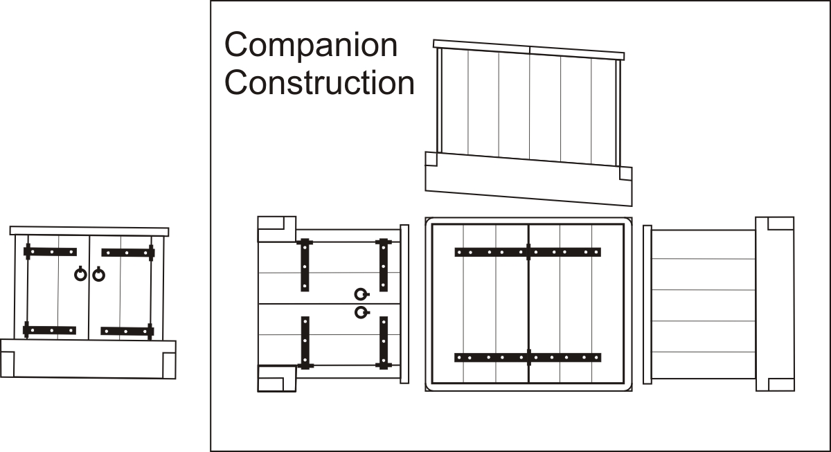
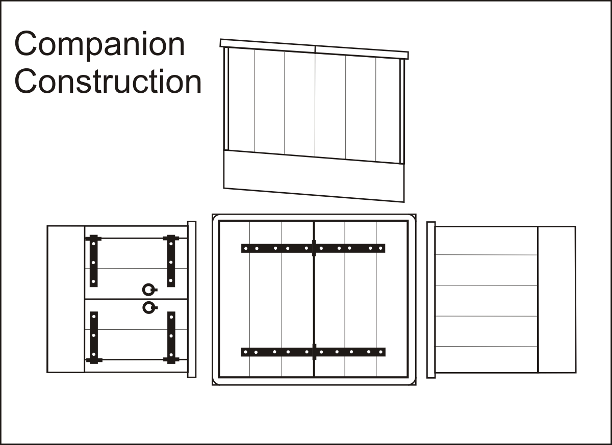
Some notes about the companionway that I will be building next. It is a typical companionway. They are all similar. Some have a more sloped top. But I drafted the profile shown on the original draft which was pretty square. I am sure you could alter it to suit and it would be reasonable and OK.
But one thing I noticed that was different from contemporary models and not consistent. Some Companionways did in fact have a coaming while other did not. Some had wide coamings that stuck out as i built for the skylight. But I decided to model a coaming that way for the skylight on the assumption that some were portable and could be lifted out and replaced with a simple grating for air circulation. But the Companionway is different. My plan shows it with a thick coaming but I may model it without as in the example provided (Second drawing and photo). This way anyone building her can have more visual info and can decide which they want to choose. I guess you can say the image below still shows a coaming but it is just not wider than the companionway which I have seen in other examples. There are such a wide array of different configurations it can get confusing.
I welcome any discussions about it.
Chuck
-
-
-
Thank You very much,
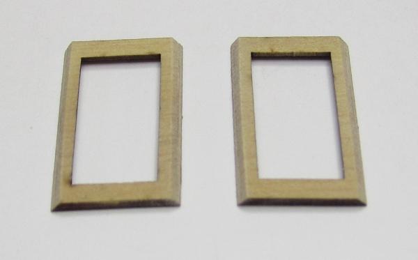
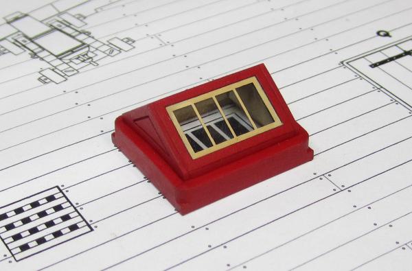
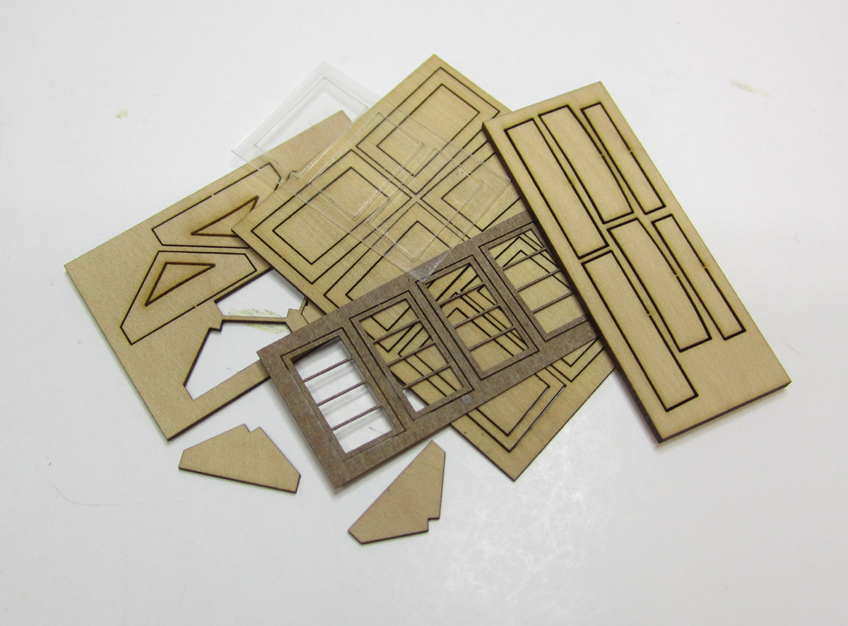
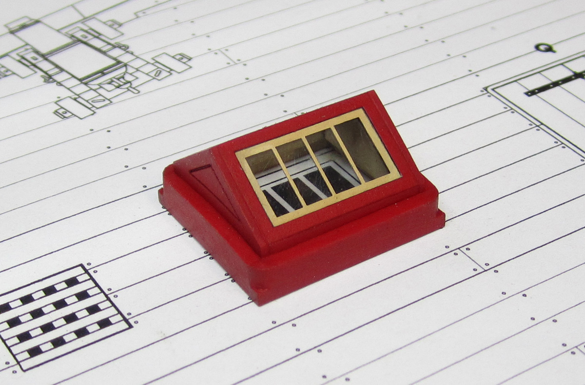
Today I decided to build the skylight. There are many shapes and sizes shown on cutters. This matches the original draft but I imaging any similar would do. I decided to make this a mini-kit. All of the parts are laser cut from boxwood, laserboard and acetate.

First I doubled up two parts to form the "lip" I will need to build this thing. There are some funky angles on the skylight because after its built the fore and aft sides must be vertical. So it was a challenge to say the least. This was done for the sides and the window frames.
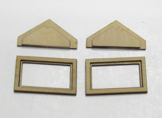
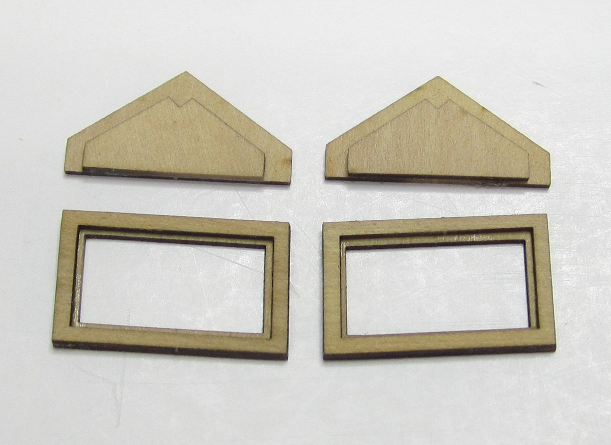
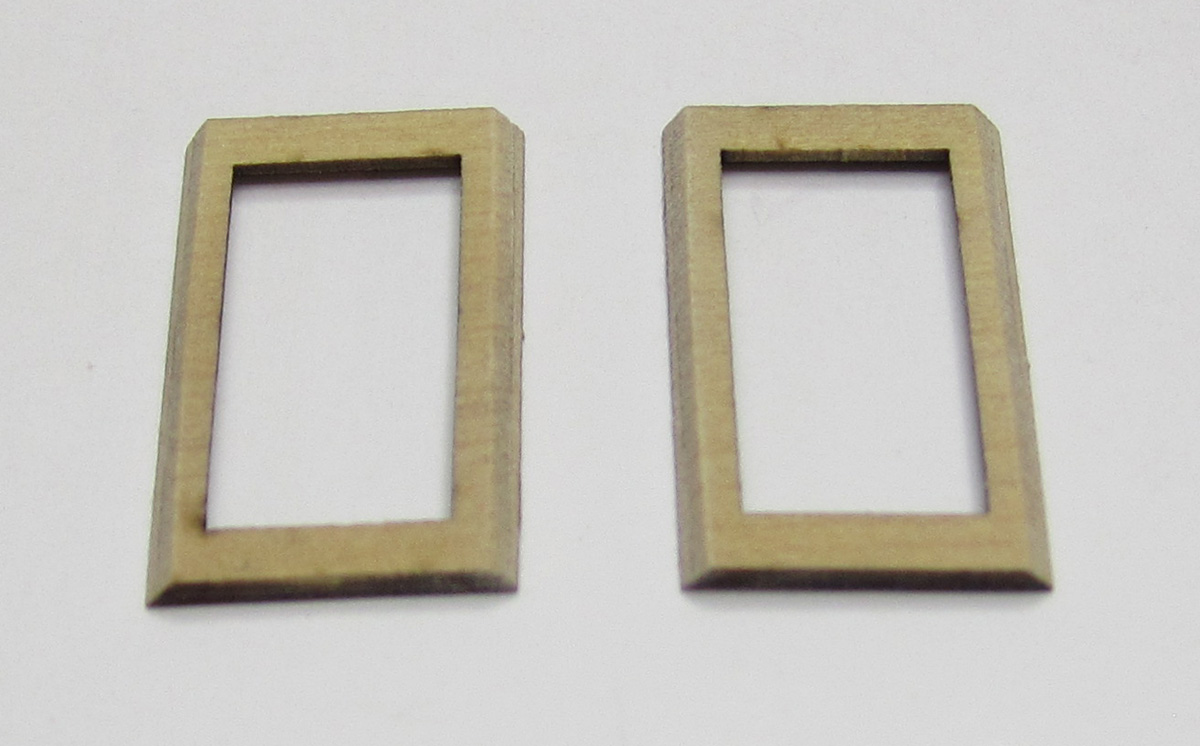
Then the window frames of the roof were beveled on the top and bottom edges. This was very important so they would fit together tightly in the next step. I used an emery board.
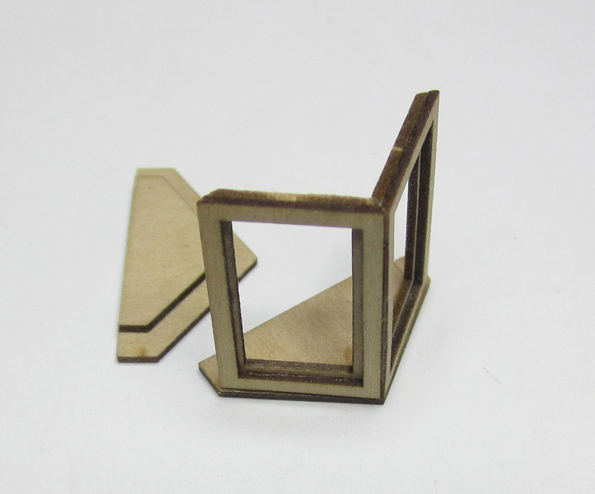
Rather than complete the frame and then add these on top, I decided to build the roof first. I tried a first prototype the other way and it was hard to get all of the angles correct and doing it in this order solved the issues. The two halves of the roof were glued to one of the sides as shown. It helped to keep the whole thing squared up and interestingly this made it easier to build..
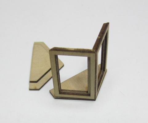
Then the other side was added and finally the two port and starboard side pieces beneath the window frames. This finished the initial framing. I know I am going to paint this red so I filled even the smallest cracks and sanded it afterwards.
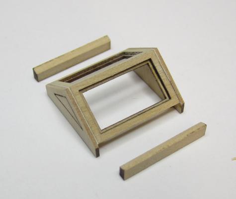
Finally a coaming was added around the skylight frame. This coaming was not as thick or as high as the coaming for the main hatch. Because it was going to be painted I didnt bother with lap joints. Note how the skylight doesnt sit flush on the ground. It is lifted off the coaming by half of the width of the timbers. This helps keep the decorative etched molding nice and neat with equal distance all around it. The fore and aft sides were done first. Then port and starboard. The corners were rounded with the right angle jig like the coamings for the main hatch to finish it up. Then it was painted red.
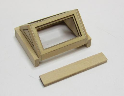
Finally the laser cut acetate windows were dropped in position along with the skylight window frames. The later was cut from very thin laserboard and painted to look like boxwood. None if these items are glued to the deck yet. I am waiting to finish up the companionway next and then I should be ready to start planking the deck around these elements.
- SailorGreg, robin b, captainbob and 28 others
-
31


18th Century Longboat by Erik W - FINISHED - Model Shipways - Scale 1:48 - First wooden ship build
in - Kit build logs for subjects built from 1751 - 1800
Posted
Lovely!!!