michael mott
-
Posts
5,200 -
Joined
-
Last visited
Content Type
Profiles
Forums
Gallery
Events
Everything posted by michael mott
-

HMS Sphynx by TBlack - 1:64
michael mott replied to TBlack's topic in - Build logs for subjects built 1751 - 1800
I am pulling up a chair Tom, should be fun to watch. michael -
Very nice Leo, these were some of the most beautiful hull and sailing vessels ever designed in my opinion. Michael
-
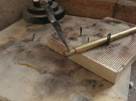
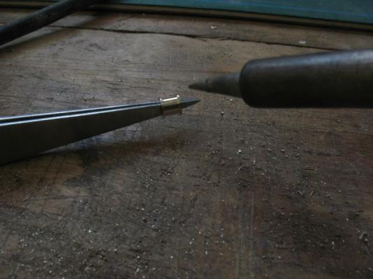
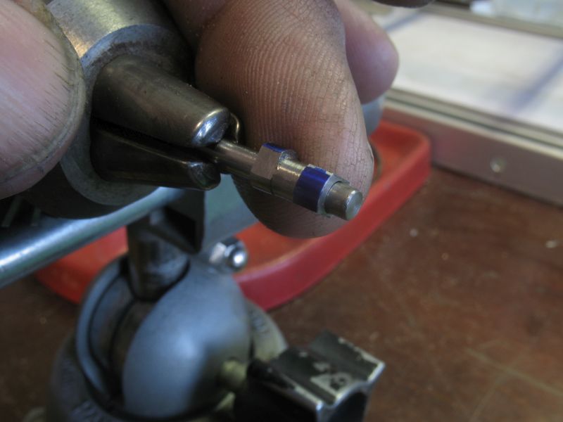
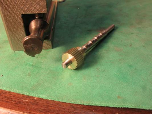
Jeff, Row thanks for your comments, and to all who posted likes. Spent some time today cutting up firewood so did not get as much time in the shop as I would have liked. This evening I did manage to make a 75DP gear cutter took a long time to figure out how to hold the cutter in order to cut the gear using the shaping principles, the first attempt at making the tool to make the cutter I did not get the pins hard enough and the steel cutter blank damaged the pins so a second hardening did work. I rotated the pins to get a clean area for the tool. The first gear blank turned out to be just some ground mild steel and did not harden at all. the second one was made from some 1/2 inch drill rod I also changed the type to an integrated shank and cutter. The first pic shows the tool to make the cutter shaping the blank cutter. the next shows the cutter after hardening and grinding the cutting face. The next one is a quick test on some 3/8 diameter brass I just wanted to see how it cut this is a crude 30 tooth 75DP gear the final gear will need more care setting up the cutter to the tangent of the gear blank and the depth of cut will need proper measuring , but at least I know I can make one. I still need to make a second cutter for the 60 tooth gear because the cutters are designed to cut a specific range, the one I made today is for gears ranging from 26 teeth to 34 teeth and is a number 4 cutter the other one is #2 cutter which has a range of 55 to 134 teeth. Michael

-
The hull is looking good Kevin, I also like the cross planking of the hull. Michael
-
Very nice Bob, that was rather fast, looks like it will be a breeze to add in the interior detail with all that open space. Michael
-
Sherry the cannons look very good, once painted one would never know they are not cast metal, excellent work. Michael
-
At Toni's suggestion here is a link to stretching paper for those who might be interested in the priciples. Paper dries better when exposed to air on both sides. Michael
-
So Ed you don't sleep either, by the looks of it. Amazing the amount of superb modelling in such a short time. Michael
- 3,618 replies
-
- 2
-

-
- young america
- clipper
- (and 1 more)
-
Good luck with all the changes Walter and Happy New Year to you and your family. Michael
-
HMS Alert 1777 by Jaekon Lee - 1/64
michael mott replied to Jaekon Lee's topic in - Build logs for subjects built 1751 - 1800
Lee I have just finished going through your build, what a beautiful job you are doing. Your workmanship is very clean and crisp, I shall continue to follow along. Michael -
Remco, Greg said it best, however I have to say your workmanship is exquisite. Michael
- 1,215 replies
-
- 2
-
-
- sloop
- kingfisher
- (and 1 more)
-
The frieze looks great Toni. Michael
-
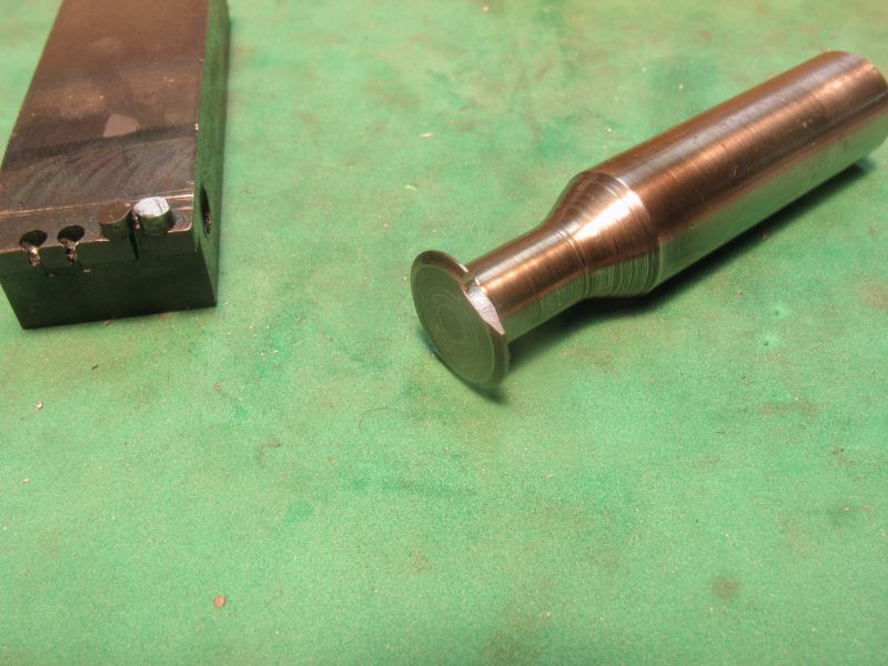
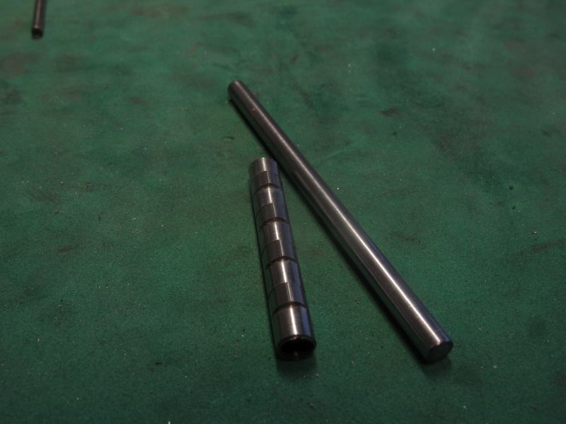
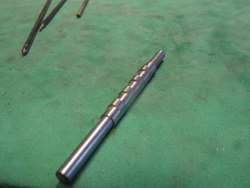
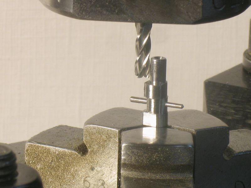
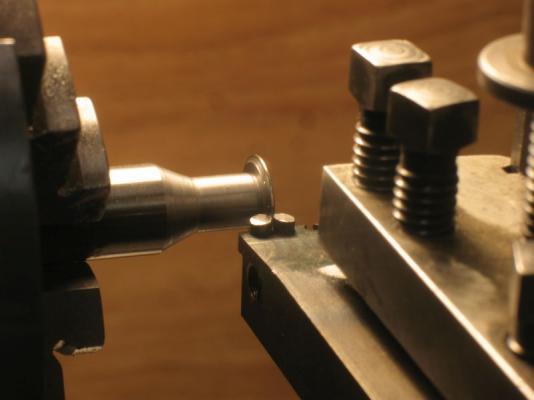
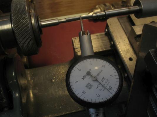
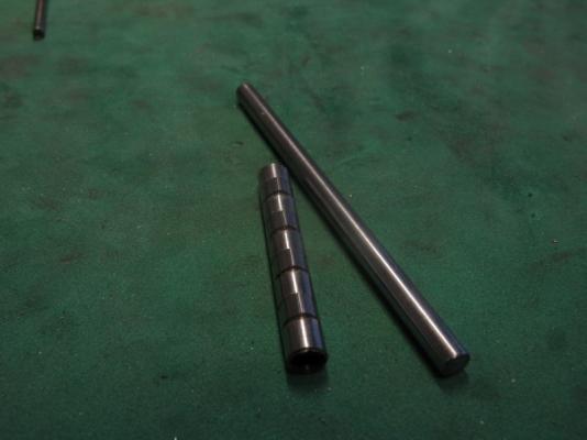
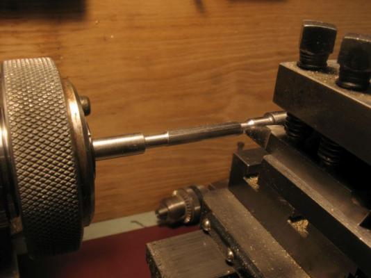
Steve thanks. I finished up the rough shaping and polished the long form then cut the sections down to the root diameter.The lift ended up being .021" I can live with that. the root sections are machined to .156" diameter bored reamed to .125" and parted off ready for pin holes in the root sections slipped onto the .125 shaft. Michael

-
Looks great Patrick, moving right along. Michael
-
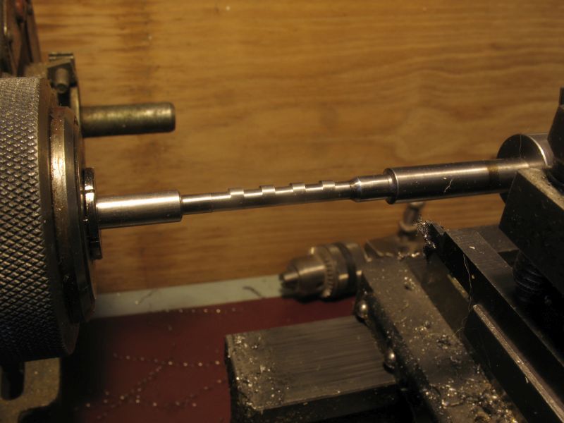
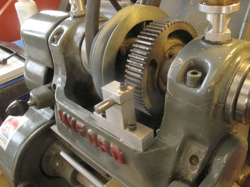
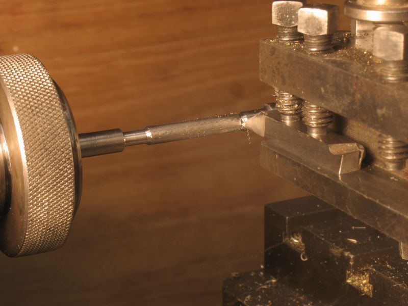
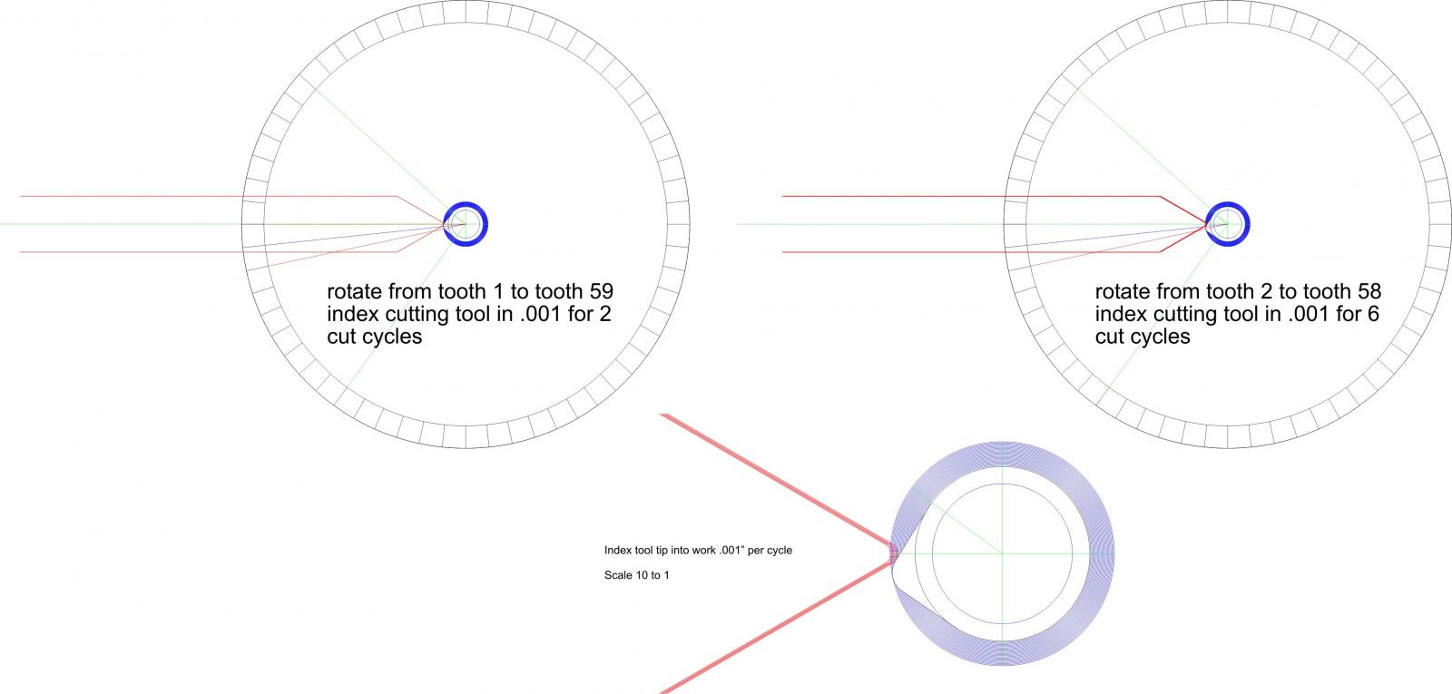
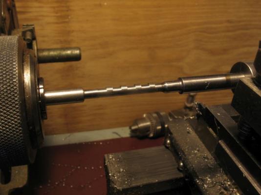
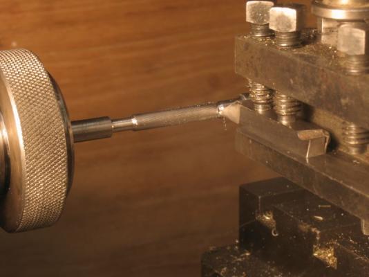
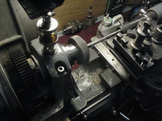
thanks evreyone for the encouragements. The cam cutting is working well a little slow but I am pleased with the way it is shaping up. I made a small indent pin for the Myford this morning before starting on the shaping. the wheel was progressively marked with the teeth that would be left out until I got to the 1/2 way mark from both sides of the lobe apex the cutter was rounded a bit more after this cut Still .008" to go before the final clean up. Michael


-
Ed try th ho and N scale model railroad supplies, I got some extremely fine chain for a commercial model many years ago. I had to represent the catenary arch of hanging power lines responsible for a fire, for a court case. My client won his case eventually against the city and power company. Bruce the model looks great and i see the block of the deck. Michael
-
Good morning Ed, thanks and yes I will harden them after the holes have been drilled. Thanks to all who added likes today I just looked at the PDF at 800% at the 10 to one image there you can see the clear incremental cuts, I am impressed I did not realize that I would get such good resolution in the PDF. Michael
-
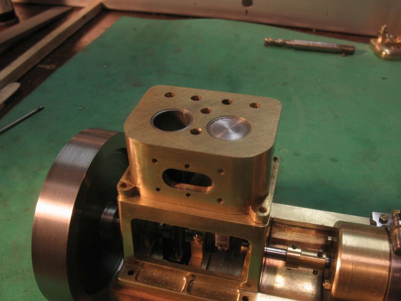
Nigel I had to look up what wills gaskets were. I will not be using them I am still deciding how to fix the head to the top of the cylinders my splitting it off was a compromise on my part because the original had it all cast as a single piece. Some of the model engine builders have used a high temp J B-weld. Michael
-
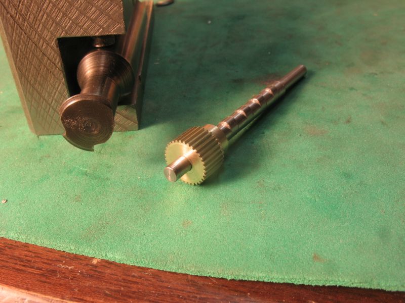
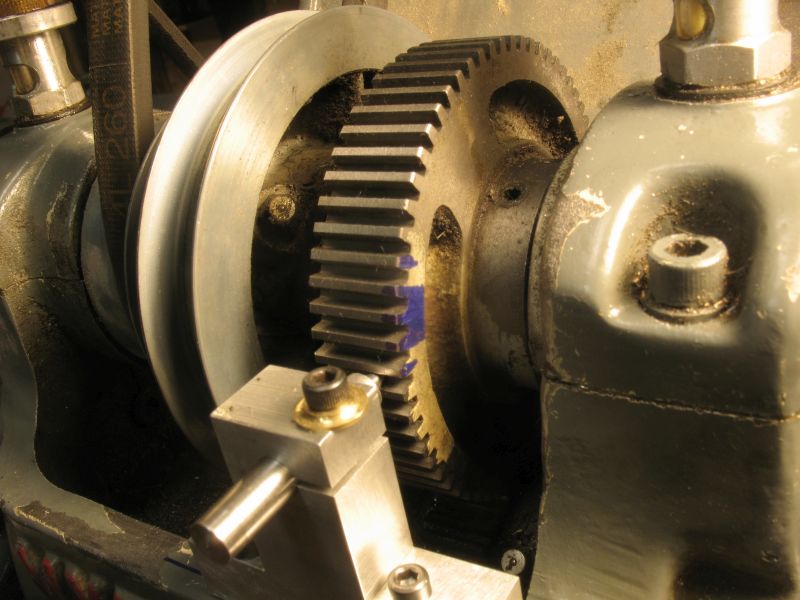
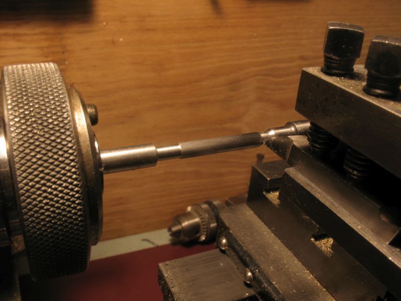
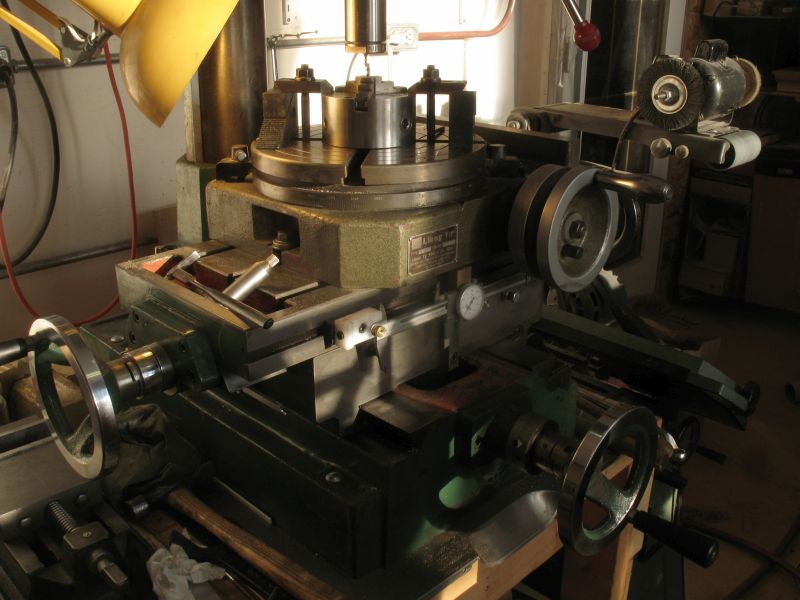
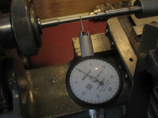
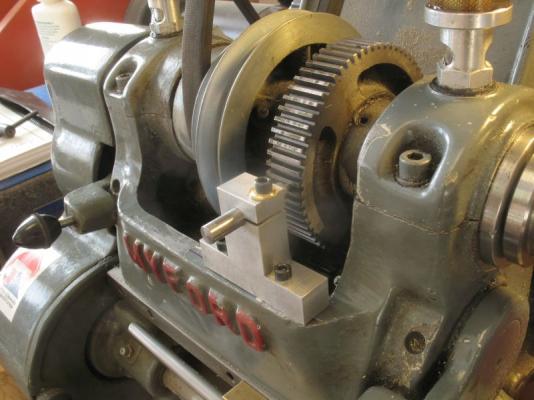
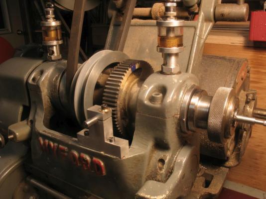
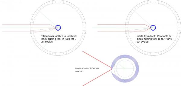
Druxey,Nigel, and Mark, thanks for looking in yes ouch indeed. I did a test cut this evening with the sharp nosed bit sideways and am going to cut the cam form as a single piece about 1 inch long. I am going to use the main gear that is normally used to set the headstock in back gear because it is a 60 tooth gear so I will set up an indent so as to lock the spindle in the 6 degree increments, the height of the cam is .022" from the cylindrical body so mapping out the 22 cuts using the gear to index I will be able to form the lobe then clean it up with files and wet and dry polish the hole thing then drill and ream for the 1/8th shaft part off the cams and then locate them and set up a dial to position them drill for the pins then when doing the final assembly use some loctite as well as the pins cams made on lathe.pdf Thanks for all the likes Michael
-
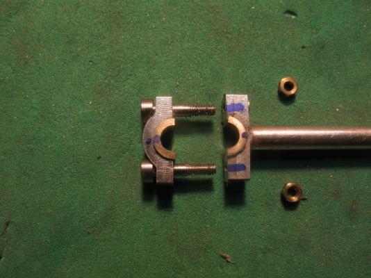
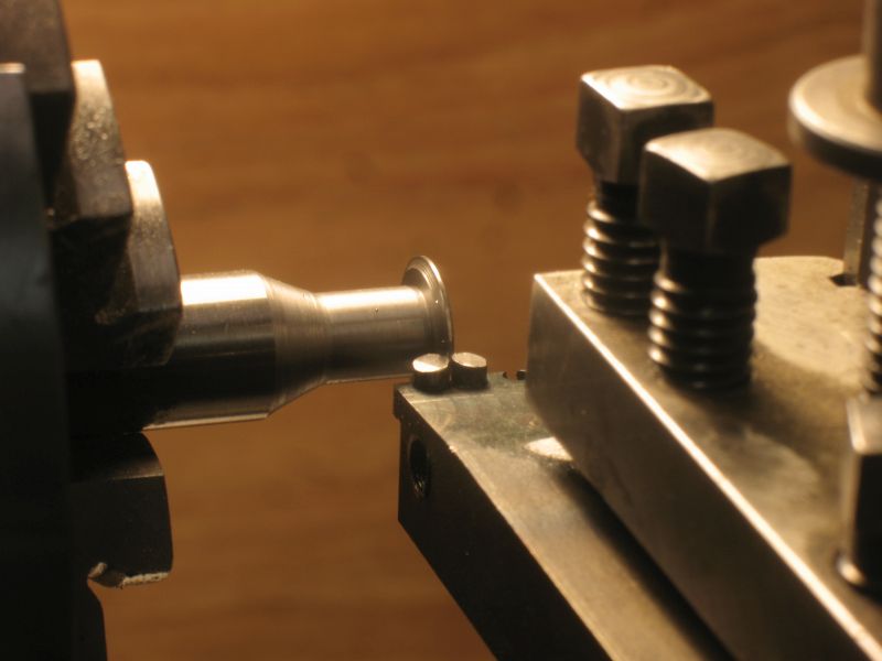
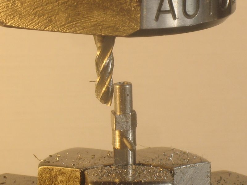
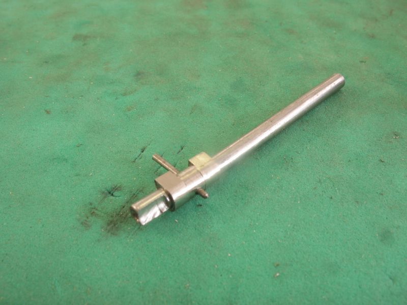
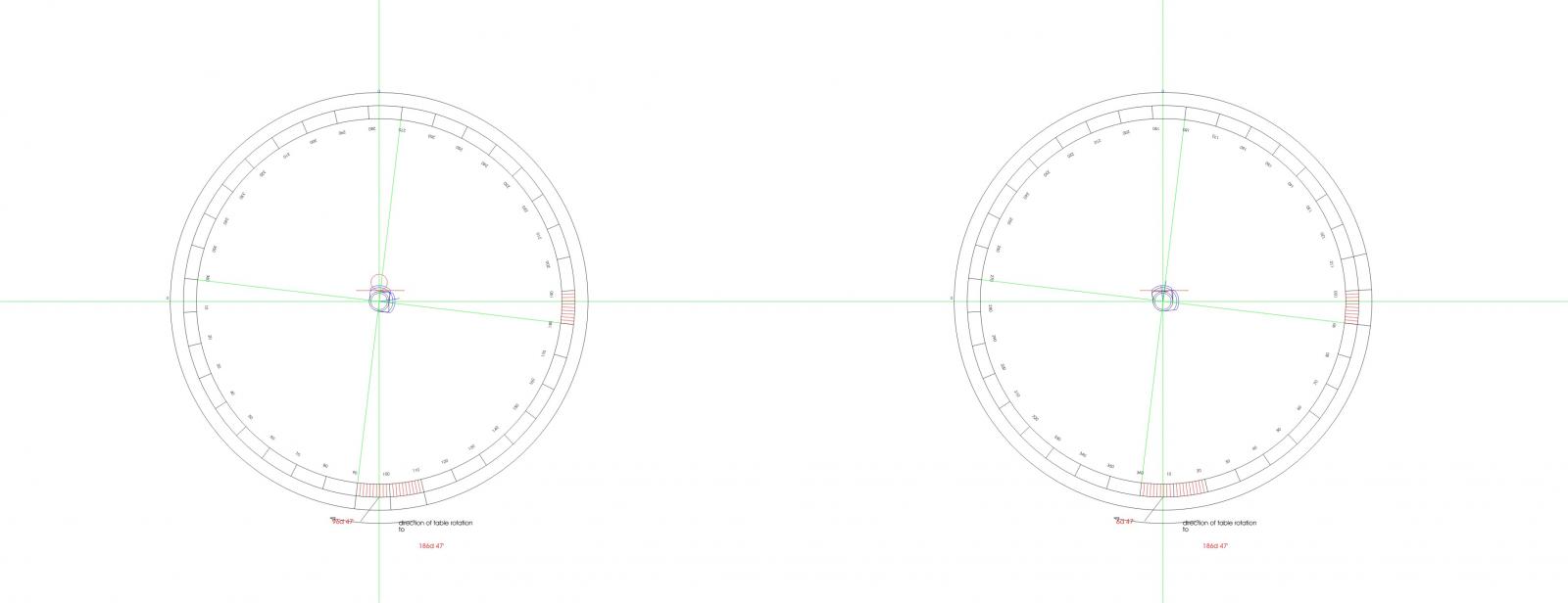
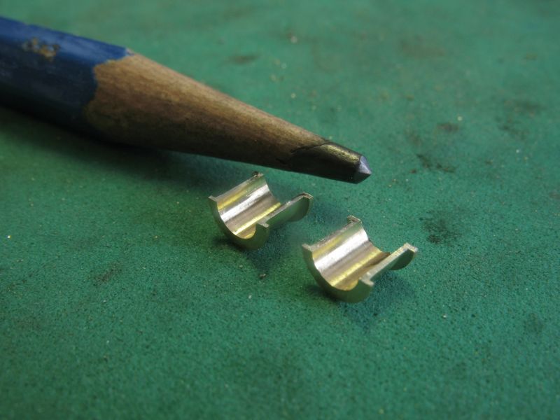
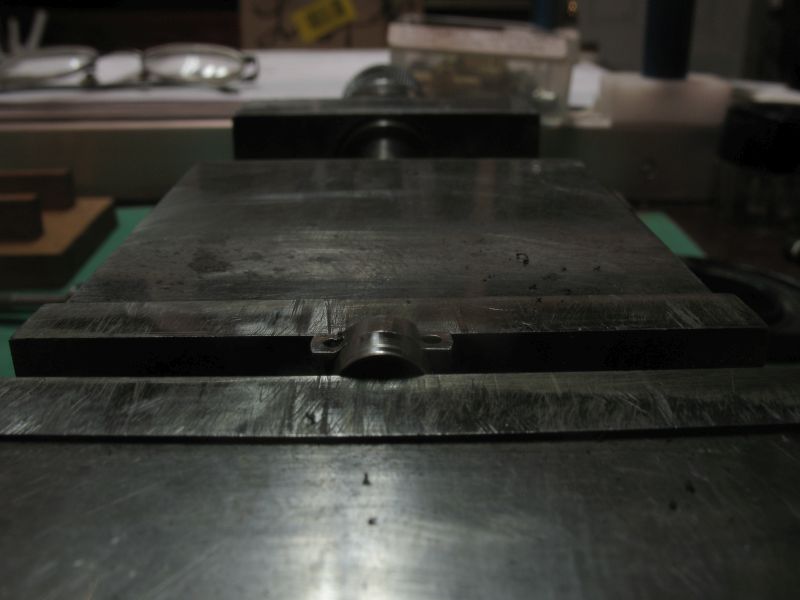
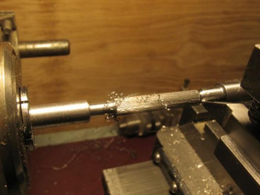
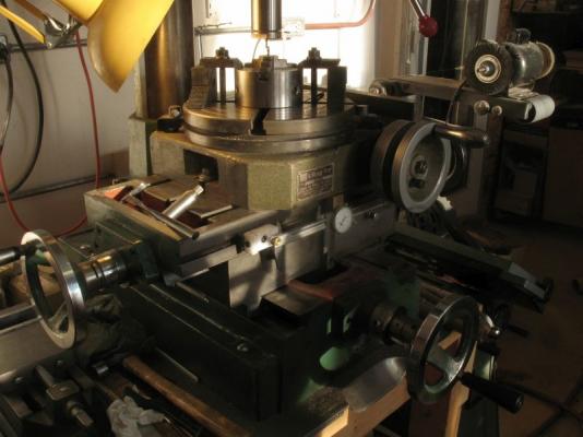
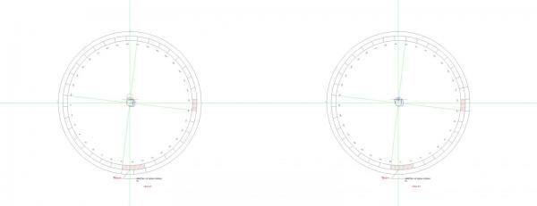
MarkT, Steve, Nils, Ed, Mark, Druxey, Matt, Bob, Jack, Row , Denis, and Remco. thanks for your kind remarks Mark I thought I was on track to make these in pairs 112 degrees rotated from each other. First turning up a trial piece to the major diameter of the lobes, then using the taper pins I fitted the piece to some 1/8th diameter drill rod rough filed them at 90 degrees like this. My thinking was that I could then use the rotary table and the mill to finish each lobe by following a table of offsets and rotating the piece. I drew the rotary table to how the process would work. camshaft template.pdf The part was then set up in the mill The first lobe worked well and after removing the pin and flipping it over end for end I was ready to cut the second lobe. After making the initial cuts to remove the bulk of the material for the second lobe i was getting ready to make the final circular cut around the back side of the lobe when I realized I had cut the wrong side of the rough block of material basically leaving both lobes in the same plane. In order to satisfy myself that this was actually the case I went to rotate the table to get a better look. the cutter was still rotating and I grabbed the wrong handle because I had not pulled it off which I normally do when working the rotary. I gave the lower handle a full turn and instantly uttered a censored word! not only dit the cutter eat into the work bending the shaft but also snapped off a bit of the cutter. the result So now I need to rethink the whole operation. Next I am going to make a long single lobe and then part off the individual cams and pin them separately, I can salvage the rest of the cutter it will need a bit of regrinding on the end but that is not much more trick that sharpening a drill bit. A long winded answer to you question. Mark the buttons are some drill rod turned to the diameter that I want the finished curve to be, the smaller diameter slides into the hole and the larger diameter pushes up to the material that will be shaped Once the two diameters are made I part it off and then heat it to cherry red and quench in water the button is then to hard to be affected by the file. Matt I think that the splashing will do the work. Row, Hmm the pressure is on, the original notion was not to add them, But I am thinking it might be better to add some. Off for a swim at the local pool to warm up and console myself it was chilly in the shop this morning -2 degrees Celcius, -30 outside probably cooled my brain down and that is why I forgot to remove the mill handle. Oh well these test are there for us to learn from, no point in getting too cranked about it. Cheers Michael


-
Great stuff Jeff, looking forward to seeing how you use all the new toys. Happy new year to you and your family. Michael
-
Nils there is always so much to see in your photographs, the amount of detail is amazing these must have been very busy places for the seamen. All the best in the new year to you and your family. Michael
-
Mike, thank you for the details, this is going to be very interesting to follow. Michael
-
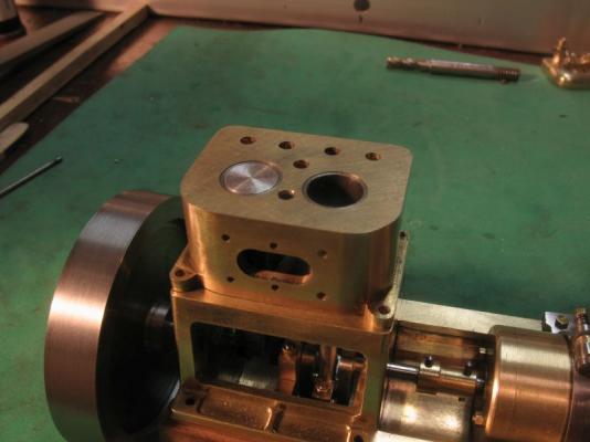
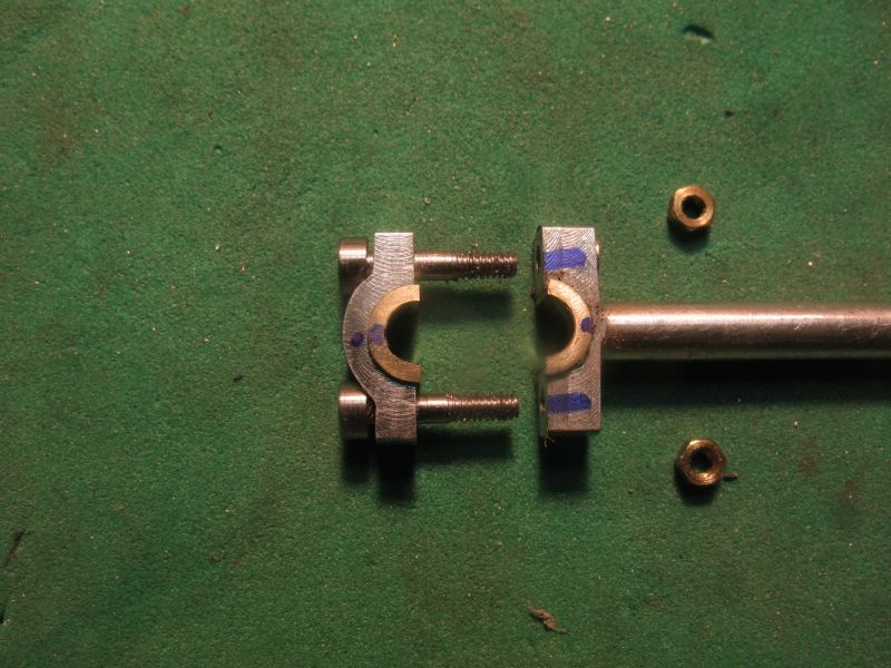
Today I finished the bushings for the con rods The first picture is showing the soldered rod ready to be machined the next is showing the bushing ready to be de-soldered. ready to be installed in the big end of the rod. filing to shape with the hardened button ready to be assembled test fitting and finally here is a video of the engine to date. That is a big milestone out of the way now I can move on to the camshaft and valves. michael