gjdale
-
Posts
4,897 -
Joined
-
Last visited
Content Type
Profiles
Forums
Gallery
Events
Everything posted by gjdale
-
 Thank you one and all for the sympathy/empathy (for those who have been here themselves!) and general good wishes for the repair. I'm pleased to report that the bosun has done a thorough inspection of the repair job and declared it fit for sea (sorry, no pics yet). All of the Fore and Main yards have now been re-fitted to include Brace Pendants, and the Fore and Main lower yards have been fitted with long tackle blocks for the Yard Tackle Pendants. Additional tricing line blocks will be added to the shrouds prior to re-installation of the yards. While I had the yards off again, I decided to revisit the parrals for the top gallant yards. I decided that the previously made parral ribs were over scale for the topgallants, as were the beads used for the parral trucks. So, I bought some new beads today from a local beading supply shop, and made some new, smaller parral ribs for the top gallant yards. I'll post some pics of these, along with the method of making them, tomorrow. B.E. - thanks for the extra info re Yard Tackle Blocks - now I think you're just messing with my head I had all but made up my mind to show these triced up, and now you show me pics of them secured to the channel.......... I also note the absence of Brace Pendants in these pics....... At least the pics are consistent with the book. Dafi - extracts from ships log: "05 Jan 2014. Fore Topgallant Mast sprung as a result of lighting strike. Fished the mast where it was wounded. Employed people to repair the rigging." "06 Jan 2014. Fore Topgallant Mast repairs surveyed and deemed fit for sea. Double rum ration issued to bosun and carpenter's crew."
 -
Looking good Meredith. Looking back over your log reminded me that you use MyUS for postal orders, so I bit the bullet just now and signed up. Wish I'd remembered a month or so ago!
-
That depends on how they are fixed in place Sean. If you've used a PVA glue, apply some isopropyl alcohol to the joint using a paint brush. This will soften the glue fairly quickly and you should be able to remove the part with no problems. If you've used a CA type glue, then the same procedure using acetone should do the trick.
-
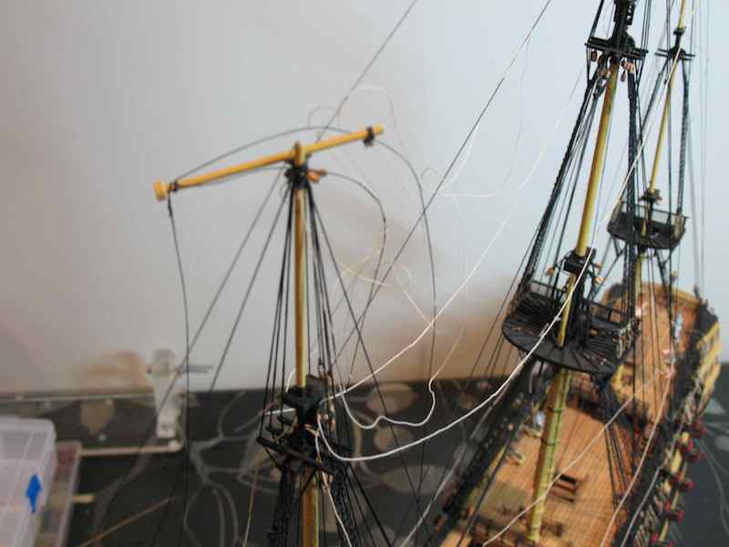
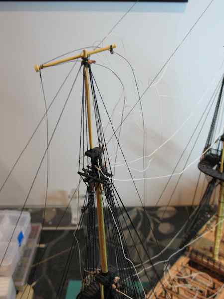
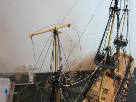
Just when you think you're making progress, nature has a way of sneaking up and biting you in the backside! Having had such a useful discussion on Yard Tackle Pendants and Brace Pendants, I decided I would remove the previously installed Foremast Yards and re-do these items - no big deal............I thought............ As I was turning the model around to gain access to undo some of the yard rigging, I very cleverly managed to catch the fore royal stay on the end of my lamp, which resulted in snapping off the upper part of the fore top gallant mast. Many rude words were said out loud - enough to bring the Admiral at the rush, thinking I'd managed to inflict serious bodily injury! Here's what it looked like: After carefully completing the removal of the yards, I was able to examine the break. Of course it happened at the weakest point, where a hole had been drilled through the mast to reeve one of the stays. My first thought was to insert a short brass pin into either end of the break, but the presence of the stay running right through the break prevented that avenue of repair. As all the rigging remained intact, and the pieces would sit back together quite well under the tension of the rigging, I decided to attempt the repair by flooding the joint with two-part epoxy. I've never really trusted CA, but the epoxy will form a strong piece by itself (probably stronger than the original timber). Once the joints were together, I then dabbed some extra epoxy around the outside of the joint. So far it seems to be holding up okay. I'll conduct a further inspection in the morning, once the epoxy has fully cured, before deeming the repair a success. In the meantime, I've completed the re-rigging of the Foremast Yards, and have also prepared the Mainmast Yards in the same way, so subject to successful mast repairs, I should be able to commence shipping the yards tomorrow. I had intended to try using Gil's method of "pinning" the yards to the masts, but am now a little nervous about that...... I'll think some more on this overnight before finally deciding.

-
Answered in your log Mike.
-
Victory by mikec - FINISHED - Mamoli
gjdale replied to mikec's topic in - Kit build logs for subjects built from 1751 - 1800
Mike, B.E. has answered on which flags where. As far as "how" goes, I believe that haliards were run through sheaves in the Mast trucks (the bit on top of the masts). -
Hi Gil, As always your log is both informative and instructive. The "pin to mast" idea looks to be a really good one. I may just unrig my fore topsail and topgallant yards to retro fit these. As I'm now leaning towards the fitting of brace pendants, it would be easier to do this off the model anyway, so no real loss in unrigging these yards.
-
Interesting link Sean - looks like a pretty simple solution. But you are going to need "a ton of rope" once you get to the rigging stage - but that's a little way off yet
-
Good to see progress on Aggy Sjors. Now ask your better half to get cracking on her Half Moon again!
- 1,616 replies
-
- 1
-

-
- caldercraft
- agamemnon
- (and 1 more)
-
Sounds like you've learned the most important lesson of all Sean - if YOU aren't happy with something, rip it out and do it over, otherwise it will bug you forever! Good move on the gratings. I'm interested in hearing/seeing more about your rope walk. How some pics of the machine and the results? What design did you use? Good luck with your IT exam. Your ship will wait patiently for your return, and so will we.
-
Thanks B.E., That kind of says that both Longridge and Lees are correct! Which means that if I were to follow as written by Longridge, I would not be incorrect....... Hmmmmm. I've been around the buoy on this so many times in my head that I'm getting dizzy. I think now there is sufficient evidence to suggest that for Victory, Longridge may be taken as being correct on this point (except I shall use a long tackle block in lieu of the common double block). Many thanks for your input B.E.
-
Looking very good David. It's interesting to see the different approaches to rigging among us as a group of modellers - much as it would have been among the various ship's Captains.
- 439 replies
-
- 2
-
-
- victory
- caldercraft
- (and 1 more)
-
Hi John, Sorry to hear of your computer problems - one of the main reasons I migrated to Mac years ago (to get away from Windoze!).
- 2,250 replies
-
- 1
-
-
- model shipways
- Charles W Morgan
- (and 1 more)
-
Hi Ed, I've just received my copy of Naiad Vol 2 - a most welcome belated Christmas present. What a beautiful job you've done with this book! I think it even ups the standard from Vol 1, and that was terrific itself. I've only had the chance to skim and dip into a few sections so far, but the way you've written this makes it a superb general reference book that will become a primary resource for me in the months and years ahead. Thank you so very much for making this contribution to the ship modelling community. Well done Sir!
-
Thanks Lawrence and Jeff. Jeff, I also looked at McKay and he generally is in agreement with Longridge. Thanks for your sketch and thoughts on how it might work. I would differ a little from your interpretation of McKay's table though. I think the quantities he refers to take into account both port and starboard sides of the yard, so there would be one inner and two outer tricing line blocks on each side (if I'm correct). The more I look at this, the more I'm inclined to follow Antscherl's interpretation...... Still hoping one of you guys/gals will weigh in with some illuminating thoughts....
-
Gosh that's beautiful work Mark. Well done!
-
Beautiful work as always Rusty. Re self-centering vs independent chucks, I'm a rank beginner with all this machinery so can't really offer an opinion of experience. The "experts" all seem to reckon that the independent jaws are more accurate. So far, I've only used self-centering ones, but as I said my experience is very limited.
-
Ouch John. Sounds like the sort of thing I would do! At least it will be hidden from view as you say, and only you and me and the other 9,322 MSW members will ever know.
- 745 replies
-
- 1
-
-
- francis pritt
- mission ship
- (and 1 more)
-
Happy New Year Augie. She's looking fabulous. Lovely job on the paintwork.
- 2,191 replies
-
- 1
-
-
- confederacy
- Model Shipways
- (and 1 more)
-
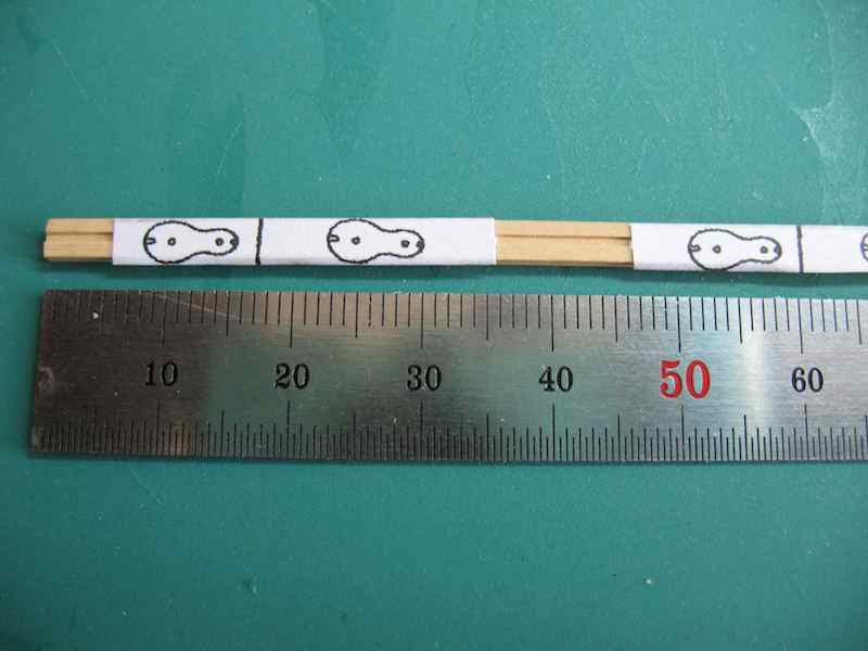
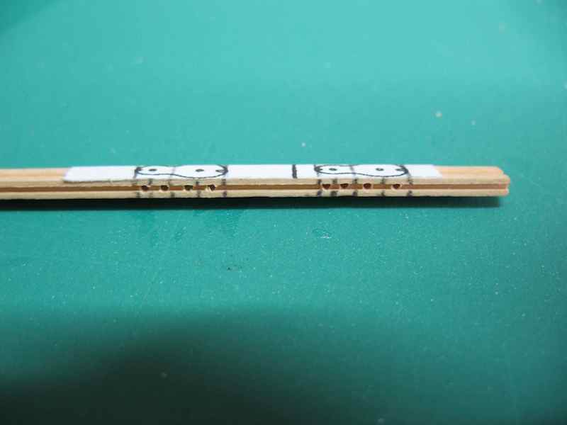
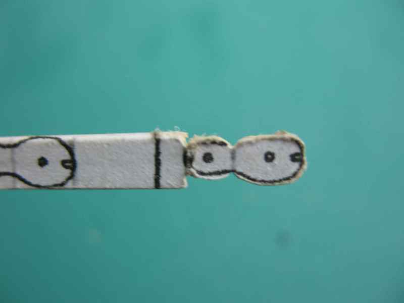
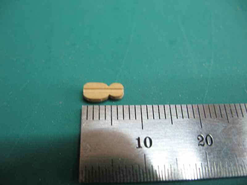
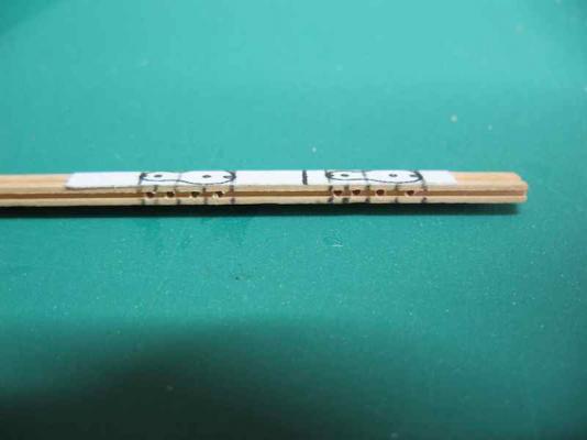
Following on from the most useful discussion on Yard Tackle Pendants and Brace Pendants, I think I've decided to show the Yard Tackle Pendants "triced up". But that leads to two more quandaries...... The first of these is to do with how the tricing was actually achieved. Lees (pg 71) says that the outer tricing line was attached to the Pendant just by the (yard tackle) block, reeved through the outer tricing line block (seized to the yard close to where the pendant would come to the yard) and then belayed in the top. He goes on to say that the inner tricing line was attached to the fall close to the hook block and reeves through the inner tricing line block. He doesn't indicate where the inner tricing line block is attached, nor where it belays, although the diagram on the same page shows the block as being on the yard close to the mast and the the tricing line then leading to the deck. In a description of the the rigging of HMS Medway (1742) on pg 175, he seems to contradict himself somewhat by stating that the outer tricing line belays "to the fore topsail sheet bits next to the upright". The same page also indicates that the inner tricing line belays to the third shroud of the foremast. Longridge (pg 242), on the other hand, says the outer tricing line is made fast to the pendant just above the (yard tackle) block, reeved through a 7" single block just outside the quarter iron, through another 7" block lashed to the first shroud just below the futtock stave and leads down on deck where it is belayed around the first lower shroud above the deadeye. The inner tricing line is made fast just above the hook block, reeved through another 7" block on the same shroud and belays on deck around the second lower shroud above the deadeye. Antscherl agrees with Lees, including the contradiction of whether the outer tricing line belays in the top or on the fore topsail sheet bits. Confused yet? I sure am!!!! The next issue is the Yard Tackle Pendant Block itself. Longridge quite clearly says that this is a 13" double block. Lees describes it as a long-tackle block. Antscherl says that at first he was confused by Steel's description into thinking that the blocks were conventional double ones while in fact these were long tackle blocks. He doesn't offer an opinion as to what convinced him of this, but does add that these were "double thin blocks", meaning they are narrower than a standard or common block of the same size. I'm inclined to go with Lees/Antsherl on this and use a long-tackle block. That then leads to the next question - what size/proportions should they be? Enter Steel. Steel describes Long Tackle Blocks as being two thirds longer than the proportion for a single block. My reckoning says then that if Longridge is describing a 13" (conventional) double block, then the Long Tackle Block would be roughly the length of a 13" block and a 10" block combined (or about 22 - 23"). At scale this equates to using the equivalent of a 5/32" and 1/8" block length, which is a total length of roughly 9/32"or 7mm. A comparison to Antscherl's choice of a 15" block for a Swan class would seem to be about right. So, how to make them then...... Noting that the blocks need to be thinner than standard, I decided to use the size of the smaller block for this dimension. I found a drawing of a Long Tackle Block and scaled it using the photocopier until it was the right overall length. I then prepared some Boxwood stock 1/16" x 1/8" and made grooves for stropping and sheaves, and stuck on the pattern: Next, I marked the divisions of the block onto the edges and drilled 0.5mm holes for the sheaves: Then I used a razor saw to make small cuts at the extremities and the "centre" of the block, and used this as a starting point for a triangular needle file to start shaping the block: I continued to file the shape until it was "almost there": At that point I was able to snap off the block from the stock and finish off the end: And here's the final result, not perfect, but I think they'll do: All I need to do now is replace the existing Yard Tackle Pendants/blocks with the new Long Tackle Blocks and then sort out just how the whole tricing thing is going to work....... Oh, and while I'm at it, I'll probably replace the Brace Blocks with Brace Pendants/Blocks as well. Okay, I'm exhausted just thinking about this. Any and all opinions welcome.


-
Welcome back Bug. Nice to see your log back - thanks for taking the time and effort to re-post.
-
Great to see this one finally underway Sjors. I'm sure it will be an enjoyable build for you, especially with your little "upgrade" kit
- 1,616 replies
-
- 2
-
-
- caldercraft
- agamemnon
- (and 1 more)
-
Great decision to go with the Sherline Rusty, you won't regret it. As for size, it's very much a personal decision. I went with the longer bed "just in case" on the basis that if I didn't end up needing the extra length then nothing lost, but if I'd gone the other way,........... Also, space wasn't an issue for me. Of course, you're going to become addicted to adding accessories now too!
- 421 replies
-
- 3
-
-
- granado
- bomb ketch
- (and 2 more)