gjdale
-
Posts
4,894 -
Joined
-
Last visited
Content Type
Profiles
Forums
Gallery
Events
Everything posted by gjdale
-
 Well done on the perseverance Jay! I saw a heard of very nervous looking goats go by just now......... I hope the next phase goes a little more smoothly for you.
- 714 replies
-
- 2
-

-
- lady nelson
- victory models
- (and 1 more)
-
Just found your build log Jay, and have enjoyed getting caught up with your progress - nice work! I'll pull up a chair and follow along from here.
- 714 replies
-
- 3
-
-
- lady nelson
- victory models
- (and 1 more)
-
This looks really interesting - I'm in. Might actually need one of these to rescue my RC Chris Craft!!!
- 96 replies
-
- 3
-
-
- tugboat
- Tippecanoe Boats
- (and 2 more)
-
Order directly from their website - very reputable and reliable company, and no problems with international postage.
-
Congratulations on reaching another major milestone Nils. She is looking just fantastic.
- 2,625 replies
-
- 4
-
-
- kaiser wilhelm der grosse
- passenger steamer
- (and 1 more)
-
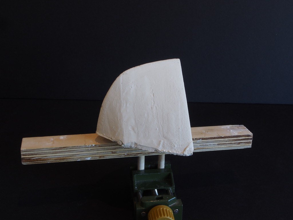
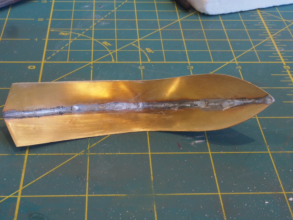
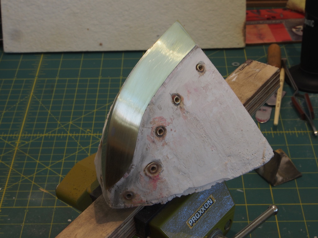
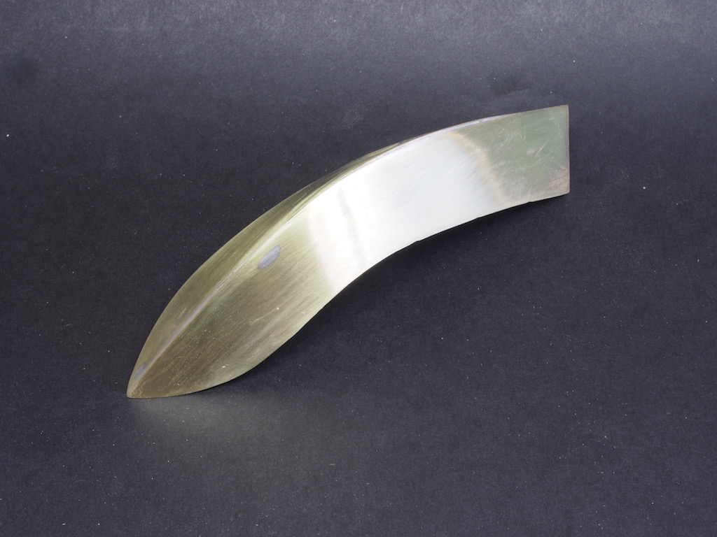
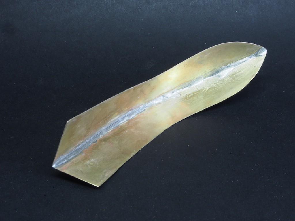
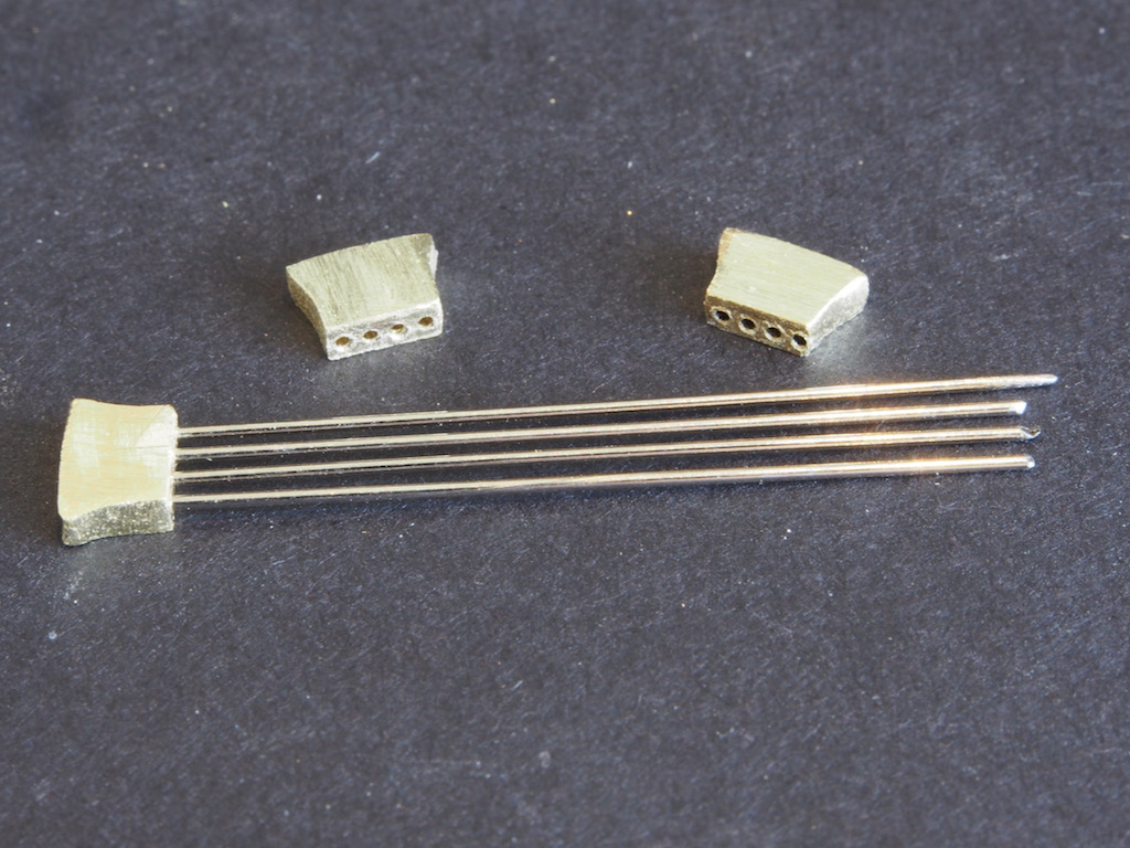
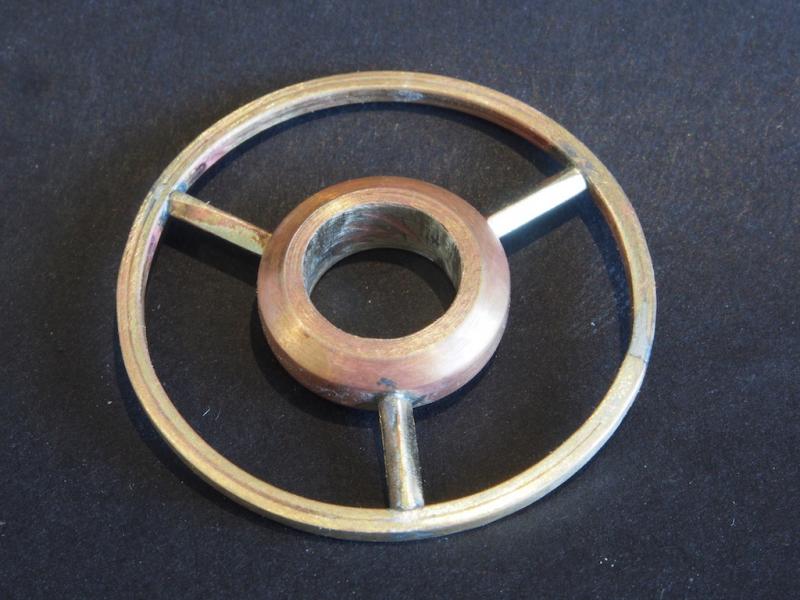
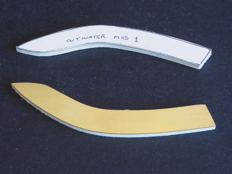
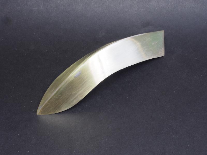
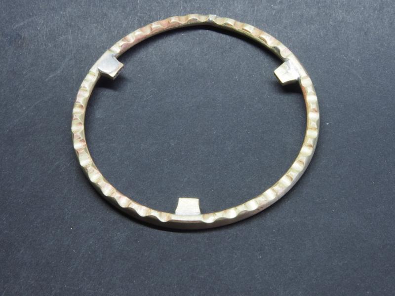
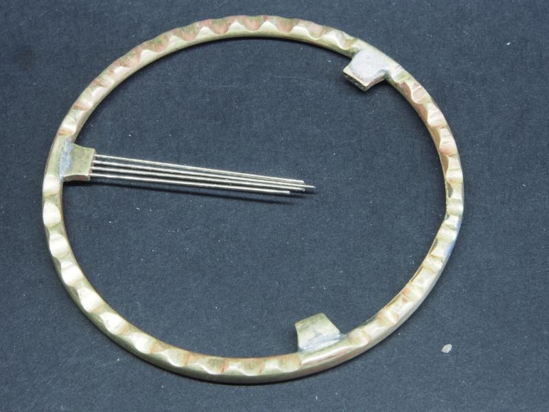
Thanks Bug and Carl, and also to those who hit the "like" button. To complete the Horn Ring, the spokes were silver soldered in place and the whole thing given an initial clean-up. In this picture, the square cross-section of the rim is evident, as is that of the spokes. All components of the wheel assembly are now ready for final clean-up and painting / plating. The CutwaterI had previously made a mould to assist in making the cutwater but it turned out to be too small, so another mould was made. In making this mould, I first sprayed the bow with a spray-on / peel-off automotive plastic paint. This gave a nice smooth surface for the mould while ensuring plaster did not get stuck to the surface of the boat. This worked well and the peel-off paint behaved exactly as the manufacture claimed. I also embedded a couple of dowels in the plaster, with the ends passed through and epoxied into a scrap of 3/4” plywood. This provided a useful “handle” to hold the mould in a vice. Paper patterns for the two halves of the cutwater were printed on sticky label paper and attached to a piece of 0.015” thick brass sheet. The brass sheet was itself attached to some thin plywood scrap with double-sided tape and the pieces were rough-cut on the scroll saw and then finish-shaped on the disc sander and spindle sander. Following the lead of others in the RC Groups Forum, I embedded a number of 6-32 threaded inserts into the mould, and made some hold-downs from some scrap aluminium flat bar. At this point, I took a slightly different approach to the task of soldering the cutwater halves. I had read of others having problems with having sufficient solder on the internal side of the cutwater, and of course I’d read their solutions as well. I did a little further reading/research on soldering and decided that it might be possible to use the properties of the solder itself to solve this problem. The key point I noted was that solder will always flow towards the heat source. To make use of this, I placed one of the cutwater halves on the mould and then wedged a ribbon of solder “wire” partly under this half before placing the second cutwater half. This meant that the two halves of the cutwater were held in place with the ribbon of solder firmly touching each half. I then painted some flux along the outside of the join, and applied heat from my small butane torch, starting at one end and moving slowly but steadily along as the molten solder wicked through. This worked very well and I should have left well enough alone….. I decided to add a little extra solder in a couple of spots but really only succeeded in adding a few globs of molten solder to the outside faces. Oh well, a little extra clean-up! In the next shot, you can see the solder on the internal join – prior to clean-up. And finally, here’s a few beauty shots of the completed cutwater after a little clean-up with files and sandpaper. I did a quick test-fit on the actual bow of the boat, and it fits neatly. The cutwater is now ready for plating and final fitting.


- 339 replies
-
- 17
-
-
- dumas
- Chris-Craft
- (and 3 more)
-
Nice progress Daria. Good to see you wearing the proper safety gear too!
-
Looking good Mark. Sorry to hear of Janet's health issues - best wishes to you both for improvement there.
-
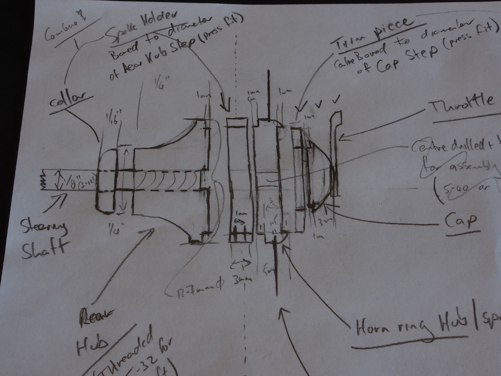
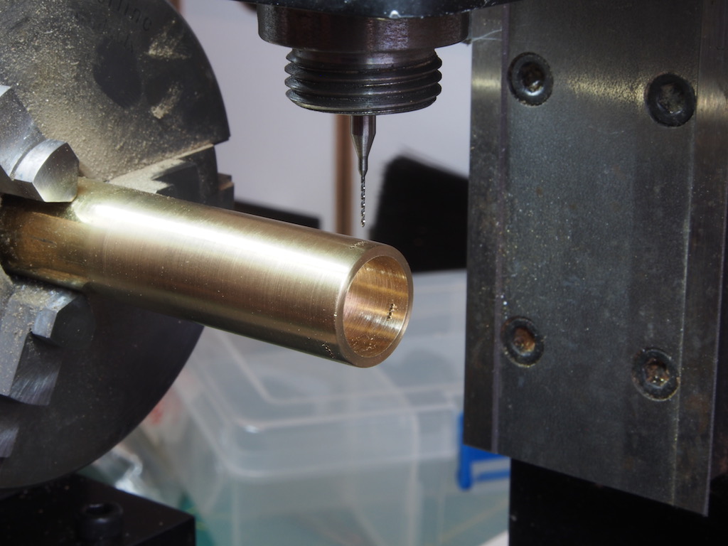
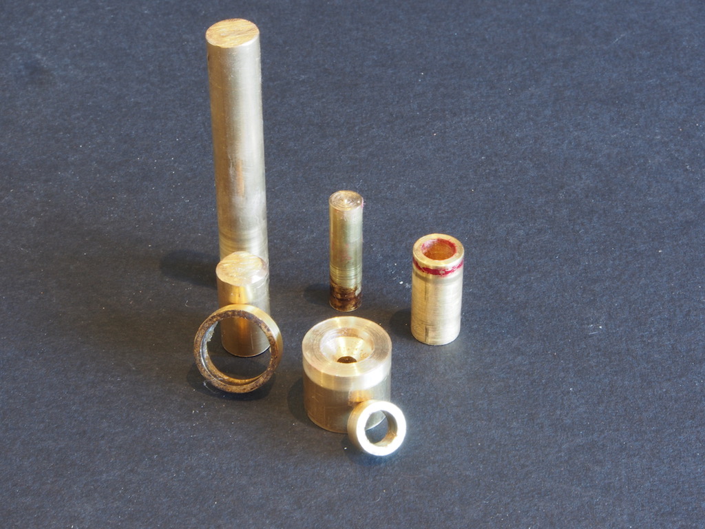
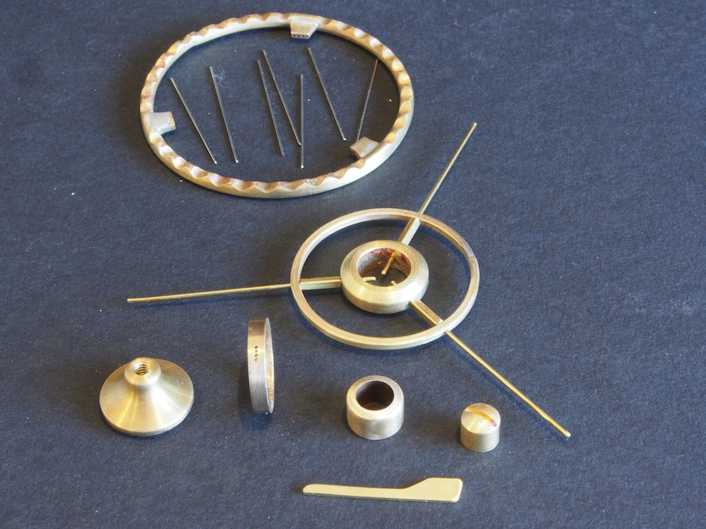
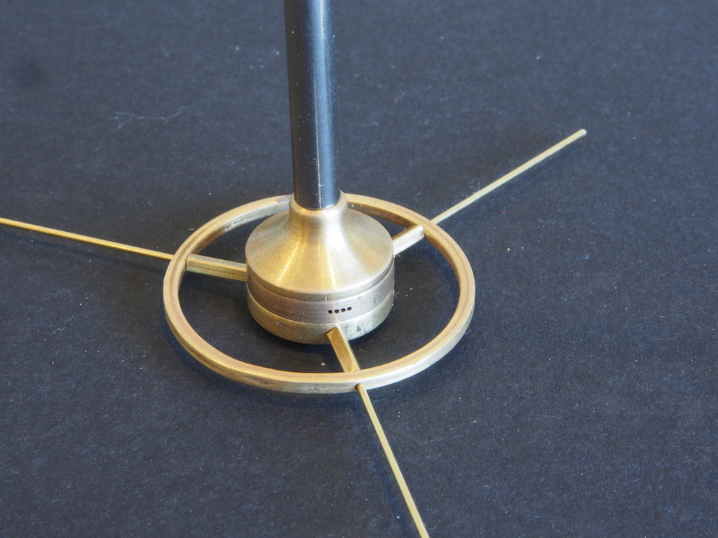
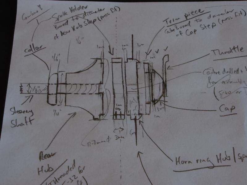
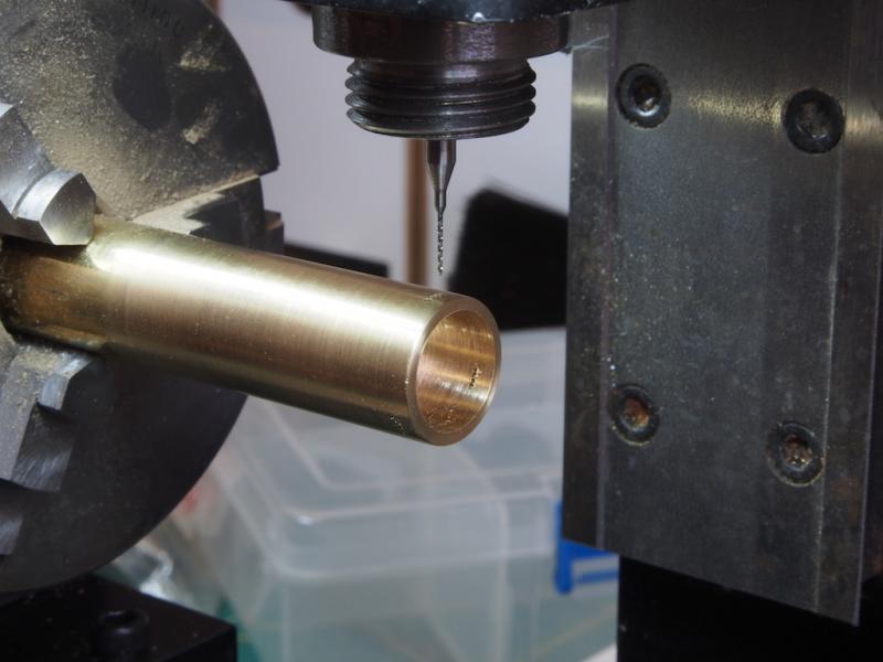
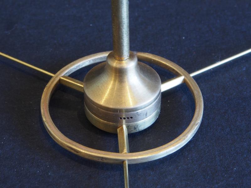
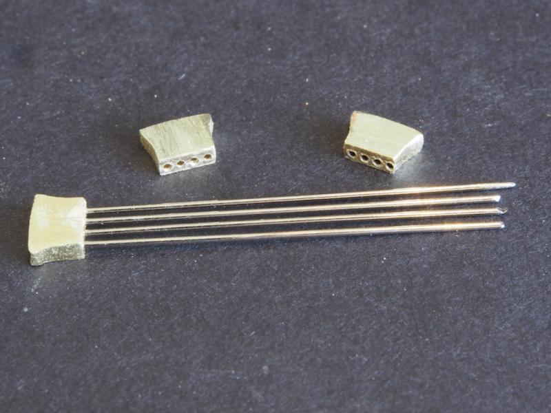
Thanks again folks for all the kind comments and the "likes" - they really encourage me to keep striving. A fairly major update today as I've completed manufacturing all the parts for the new steering wheel. Wheel Building continued - the Hubs If I thought that the hard part was over ….. The first step was to actually design my hub components. Although Kip had very kindly sent me a copy of his “chook scratchings” from the design process, I needed to make a couple of design changes to suit my slightly different approach (primarily the fact that the steering shaft will thread into the rear hub). I had several exchanges of email with Kip throughout this process and that was a huge help in getting my head around the task. Here is a copy of my own early chook scratchings. From here, I decided to make up a set of CAD drawings of each component to further understand what I was attempting to do, and also as a useful check on my own measurements and calculations. Needless to say, there were many changes to both this diagram and the CAD drawings as the manufacturing process got underway – “no plan, no matter how good, survives first contact with the enemy!” Once I had the design principles clearly in my head, the manufacturing process actually went quite smoothly…….for the most part. In fact, it went so well that I forgot to take many progress shots. In the next picture, I am drilling the banjo spoke holes into what will become the banjo spoke hub. This started as a piece of 5/8” brass rod, that was first bored to leave a wall thickness of 1.5 mm. The banjo spoke holes are all 0.5 mm in diameter and I managed to drill all twelve without breaking the drill bit. Ironically, the drill bit broke just as I was removing it from the mill. The manufacturing process required some thought as to how to hold various pieces on the lathe while they were being turned and shaped and fitted to their final dimensions. After a bit of trial and error, I concluded that several mandrels of various key sizes, both solid and centre-bored, were the most useful thing to use. I found that gluing these temporarily with CA to the stock being machined held the piece securely while being worked. The parts were then separated by the judicious application of heat from the MAPP blow torch. Here is a shot of the various mandrels I used – in some cases a combination of two mandrels were required. The rear hub was shaped by first cutting a series of steps (staircase effect) and then smoothing with a round file while still on the lathe. The Horn Ring Hub, Trim Piece and Cap piece required a radius on the end. The Radius Cutting attachment for the lathe worked a treat for these parts. The Horn Ring itself is square in section and this was formed by using a 1/16” square brass tube. After first annealing with the MAPP torch, it was bent around the same wooden buck as used for the wheel rim. The buck was first turned down to the appropriate diameter, and I must confess here to having a couple of goes at this before I was satisfied with the size. As the tube is hollow, it allowed me to insert a piece of 0.8 mm brass rod inside and extending across the join. This really helped when silver-soldering the join closed. The piece was then returned to the rotary table on the mill and 0.85 mm holes were drilled at 120 degree intervals for mounting the spokes. The spokes for the horn ring are also square in section and the same brass tube was used for this. By inserting a piece of the 0.8mm brass rod through the pre-drilled hole in the horn ring, right through the length of the spoke, and into the horn ring hub, the hole assembly becomes self-aligning. The horn ring hub itself was probably the most difficult of all of these parts to make and I had three attempts at this before I was finally satisfied. The Cap Piece, as well as having a radius turned on the end, also had a 1/32” slot cut with a slitting saw to receive the Throttle Lever, which itself was cut and filed from a piece of 1/32” brass flat bar. The picture below shows all of these parts, starting with the Wheel Rim and a selection of banjo spokes at the rear, the Horn Ring, Horn Ring Hub and Horn Ring Spokes (temporarily mounted and ready for soldering), and then across the front from left to right are the Rear Hub (note the internal threading to receive the steering column), the Banjo Spoke Hub, the Trim Piece, and the Cap Piece, with the Throttle Lever in the foreground. Putting some of these components together for the camera, here is a of shot of the Horn Ring assembly mounted on the Banjo Spoke Hub, mounted on the Rear Hub, with a temporary Steering Shaft. And lastly, the same assembly with the stainless-steel sleeve that goes over the steering shaft. That completes the manufacture of all components for the new steering wheel. The next job will be to solder the Horn Ring assembly together, and then chrome plate the Horn Ring assembly, Cap Piece and Throttle Lever. The other components will be painted an off-white (ivory) colour, and then the whole lot will be finally assembled. Once that is done, I will return attention to making the cutwater….


- 339 replies
-
- 11
-
-
- dumas
- Chris-Craft
- (and 3 more)
-
Thanks for the heads up Ben - just placed an order!
- 11 replies
-
- 5
-
-
- miniature table saw
- Byrnes model machines
- (and 2 more)
-
Thanks Sam and Carl, Sam - the soldering was done with a small butane torch (probably the same as yours). The big MAPP torch (that Carl refers to) was used to anneal the brass rod prior to bending to shape for the wheel rim.
- 339 replies
-
- 4
-
-
- dumas
- Chris-Craft
- (and 3 more)
-
Thanks Keith and Slog, Keith - yes the polishing kit has arrived, but I'm holding off on that task as I need to re-do the mould/cast of the bow for the cutwater. Hope to get that done in the next week.
- 339 replies
-
- 4
-
-
- dumas
- Chris-Craft
- (and 3 more)
-
I like the contrast of the black trucks Rusty, but hey, it's your ship!
- 310 replies
-
- 5
-
-
- cheerful
- Syren Ship Model Company
- (and 1 more)
-
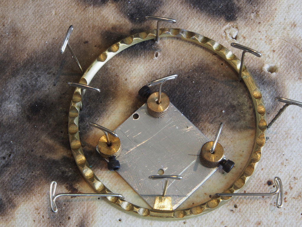
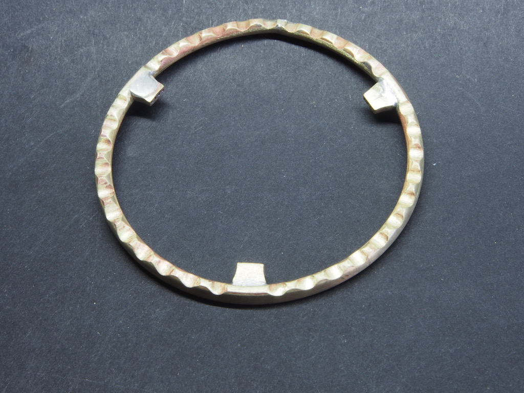
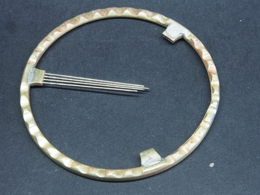
The spoke holders were cleaned up and given a bit of shape by filing. Here is a shot of the completed spoke holders, with spokes fitted in one (temporarily). The next job was to solder them to the wheel rim, again using silver solder. To hold them in the correct position, a shim of scrap aluminium 1/32” thick was shaped and drilled to accept some pins. Here is a shot of the soldering set-up. The first two spoke holders went on just fine, but the third one didn’t want to play nice. However, sheer bloody-mindedness and determination won the day in the end. While I was at it, I re-did the main rim joint as well, as there was a slight misalignment that had been bugging me. To protect the soldered joints from de-soldering while the next joint was heated, I used a heat barrier call Cool Gel, made by LA-CO. It comes in a spray bottle, but I just squirted a bit onto the soldering mat and used an old paint brush to pick up and apply the gel to joints to be protected. This was the first time I’d used this and it works really well. Here are a couple of shots of the completed joints. I’ve included the spokes in one of them to give an indication of how they will look once they are all together. They have been given an initial clean-up, but I may go back and do some more yet.

- 339 replies
-
- 22
-
-
- dumas
- Chris-Craft
- (and 3 more)
-
I'm just using "regular" el cheapo drill bits with a 1/8" shaft. I'm sure I could find bits more suitable for this, but the price seems to sky rocket as the size goes down! I'll try the conical burr for pointing next time - thanks for the tip Wefalck.
- 339 replies
-
- 6
-
-
- dumas
- Chris-Craft
- (and 3 more)
-
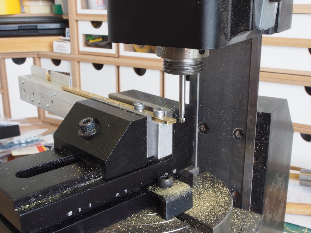
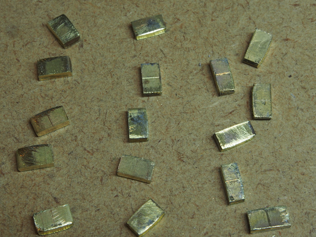
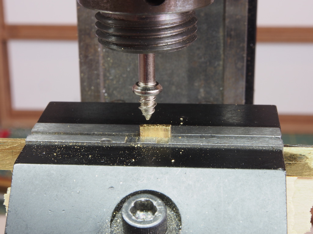
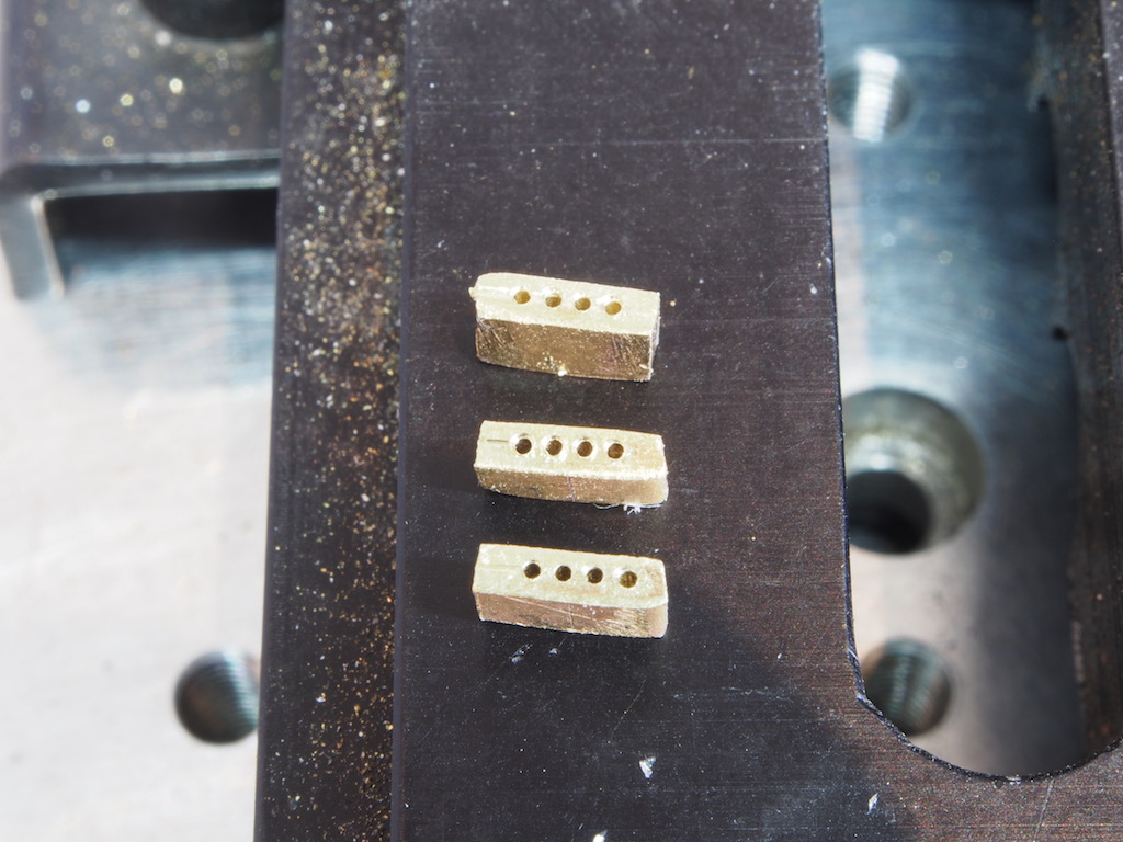
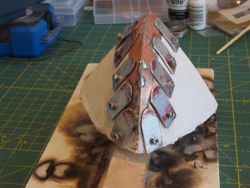
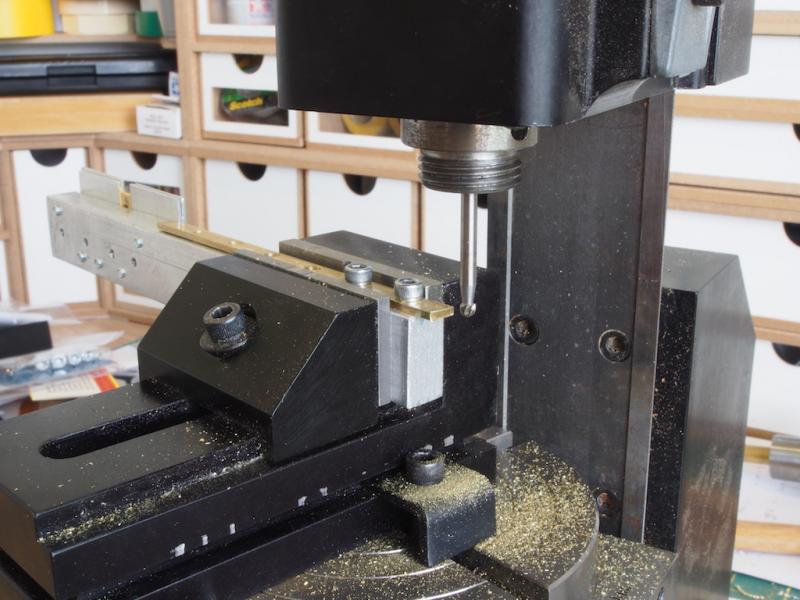
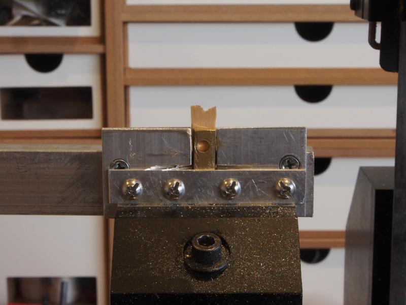
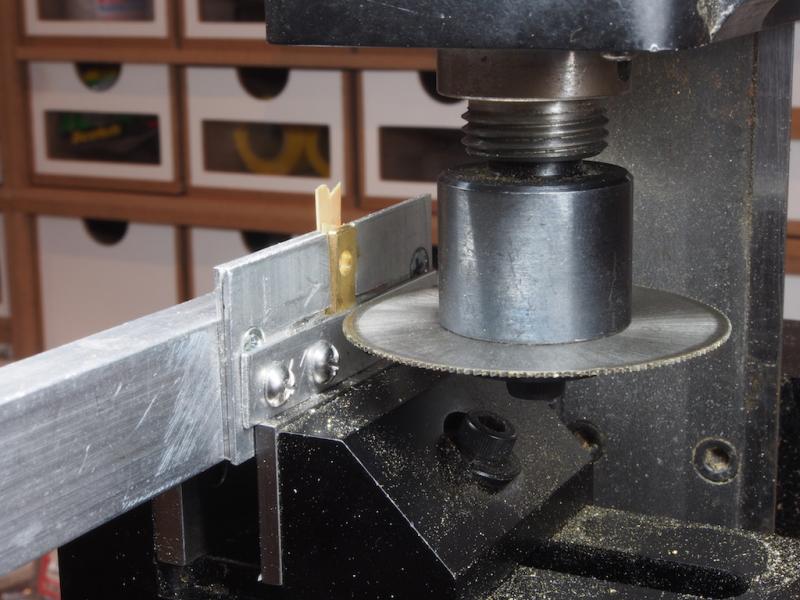
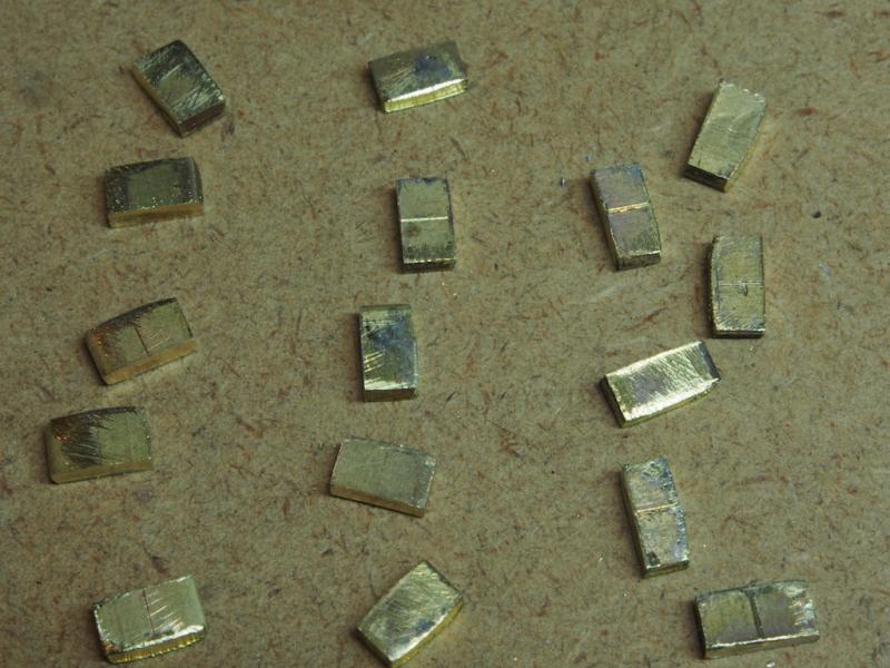
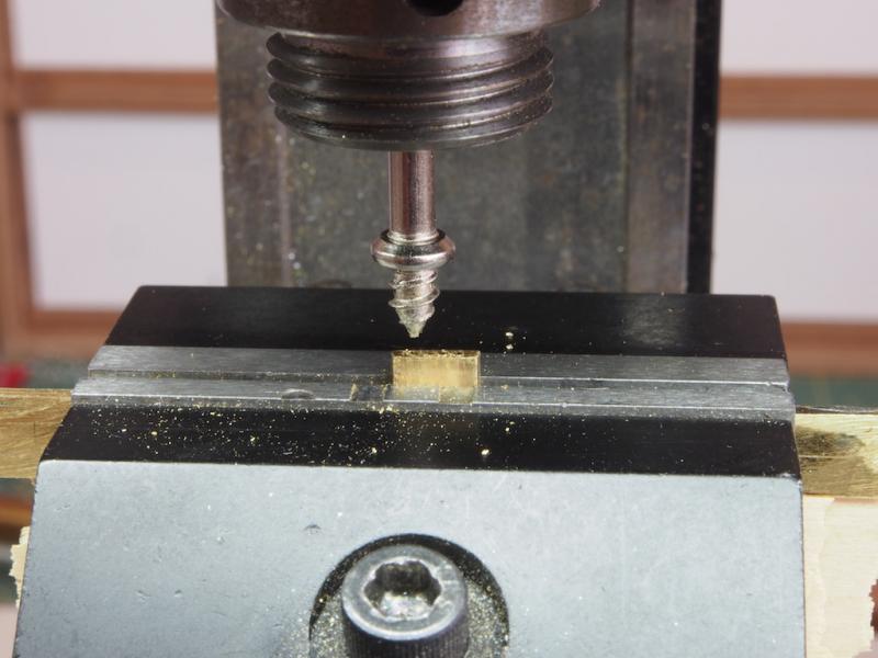
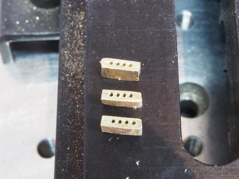
It's been a while since my last update - not because of a lack of work, but because of a lot of re-work! Drilling the holes in the spoke holders proved to be something of a challenge and very frustrating. The drill bits at this this size are very easy to break, and once broken they remain in the part and are impossible to remove, so the part then goes in the scrap. After breaking half a dozen drill bits, and scrapping as many parts, it was time to re-think the strategy. After an exchange of several emails with Kip while thinking this through, it was time to start over. I decided to make a lot of spares for the spoke holders, in case I ran into the same problem again. To improve the repeatability of the part making, I decided to upgrade my jigs. I first re-made the holding jig for cutting the radiused end, using some aluminium bar stock I had laying around. The jig is essentially the same as its wooden predecessor, but the tapped holes would retain their threading for longer. At the left-hand side of the jig, the back of the sizing jig is visible. The picture below shows the front side of this, with the part held ready for cutting. The front “fence” prevents the freshly cut part from disappearing into the ether, and also provides a reference line for cutting. With the blade set to just clear this, the part is cut to the correct height. Two 1/64” thick pieces of scrap boxwood act as wedges to hold the part securely against the fence and also provide a temporary “stop” to save the cutting blade going further into the aluminium jig behind. In the next photo, the jig has been rotated 90 degrees and is about to be advanced into the slitting saw. And here is the result – a bunch of parts that are close to identical, ready for the next attempt at drilling. The next picture shows the pointed awl-type bit from my collection of Dremel bits that served as a centre punch to mark the hole centres. These were started 1.5 mm from the edge of the piece, and the centres marked at 1.0 mm intervals. In previous drilling attempts, I had been using the Sherline Sensitive Drilling attachment, as I thought this might give better control. It had two draw-backs though. Firstly, I was not sure if I was applying the right amount of pressure, nor whether I was inadvertently applying any sideways pressure, resulting in so many broken drill bits. Secondly, it has no ready way of indicating depth and I found that when I wasn’t breaking the bits, I was drilling right through the part – something that might cause a problem when I went to solder them in place on the wheel, with the danger of solder flowing into the holes. I also discovered that 0.50 mm was just a fraction too small a hole for the spokes, so I went with a 0.55mm drill bit for this round (which was just as well, as I’d broken my entire stock of 0.50mm bits!). With this attempt, I decided to mount the drill bit in a collet and use the hand wheel of the vertical axis to determine the correct depth of cut – in this case, 2 mm. By advancing the drill bit ever-so-slowly, and backing off every 0.05 mm to clear the chips, I was eventually able to successfully drill the holes in three parts. I did still have a couple of failures. I found that the drill bits would last for about 6 holes, and then break (ruining the part again). However, as I had made plenty of spares I only needed to use two of these. At last, three useable spoke holders: The ends will now be cleaned up and shaped a little prior to soldering onto the wheel rim.
- 339 replies
-
- 10
-
-
- dumas
- Chris-Craft
- (and 3 more)
-
Breath-taking Nils! Working at such a tiny scale really does introduce a whole new set of challenges, and you appear to have mastered all of them.
- 2,625 replies
-
- 6
-
-
- kaiser wilhelm der grosse
- passenger steamer
- (and 1 more)
-
Looking good Kevin. A tip to prevent the bleeding when you mask - paint a thin line of clear coat along the edge of the masking tape. This will seal the edge of the tape and prevent any coloured paint from seeping under. Hope this is helpful.
-
Welcome back Adam. Great to see you found your way home.
-
Great to see you back Remco. You have inspired more modellers than you might imagine, especially with your tag line. I look forward to seeing more updates from you through 2017.
- 1,215 replies
-
- 3
-
-
- sloop
- kingfisher
- (and 1 more)