gjdale
-
Posts
4,894 -
Joined
-
Last visited
Content Type
Profiles
Forums
Gallery
Events
Everything posted by gjdale
-
 Nicely done Mark. I've yet to meet a re-do that I haven't preferred to the original - so well worth the effort.
 -
Congratulations on completing your first build Elijah. You've done a great job and it seems you've learned a lot along the way too, which is what it's all about. I look forward to following your next build too.
- 701 replies
-
- 4
-

-
- phantom
- model shipways
- (and 1 more)
-
Congratulations on completing another very fine build Bob. I look forward to following your Halifax build.
-
Thanks very much Hof, Mobbsie, Slog and Remco. Remco - not sure if I understand your question. If it is about the paint, the brand is Vallejo. Plating was with a Caswell brush plating kit.
- 339 replies
-
- 4
-
-
- dumas
- Chris-Craft
- (and 3 more)
-
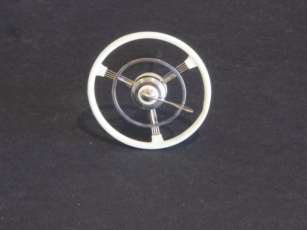
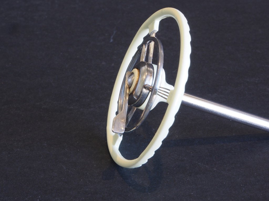
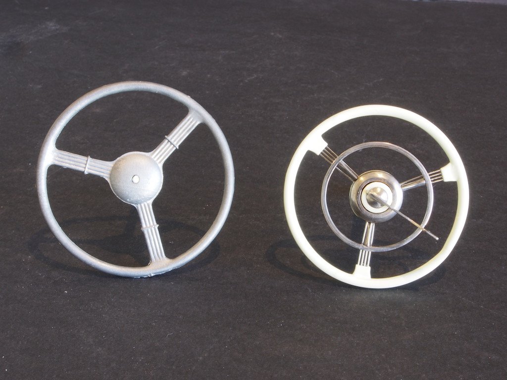
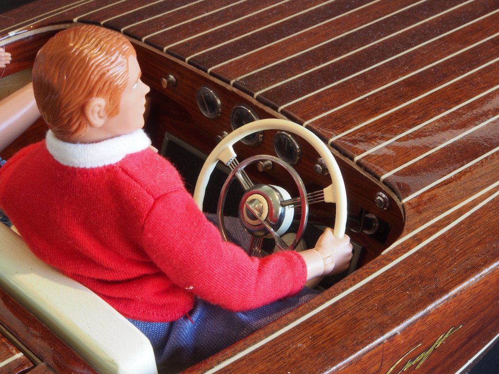
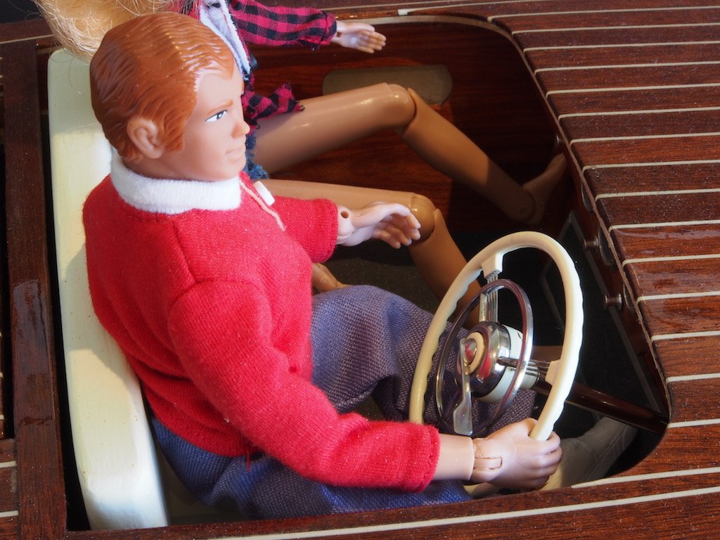
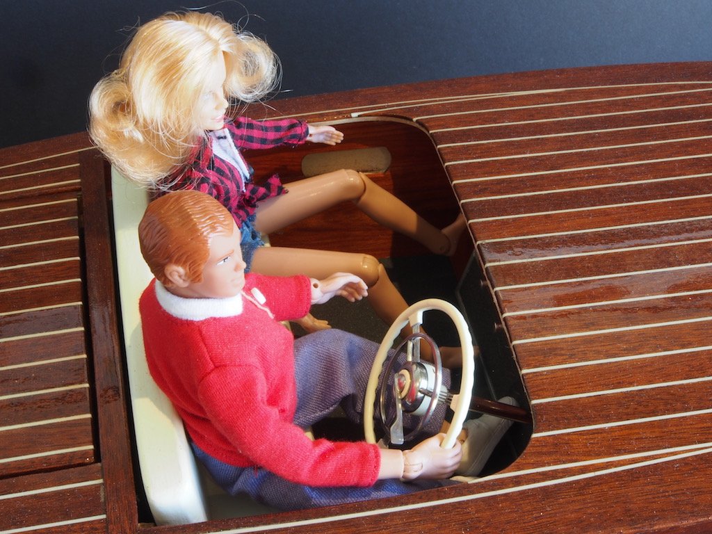
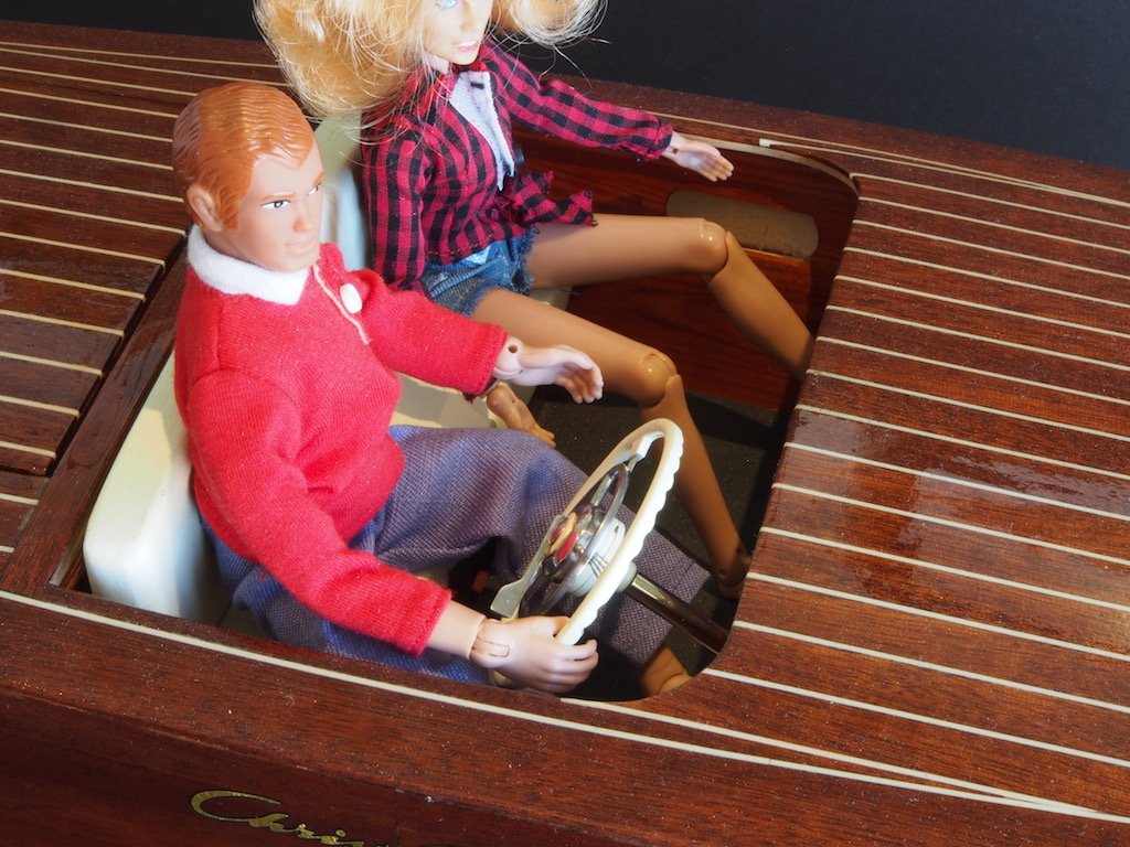
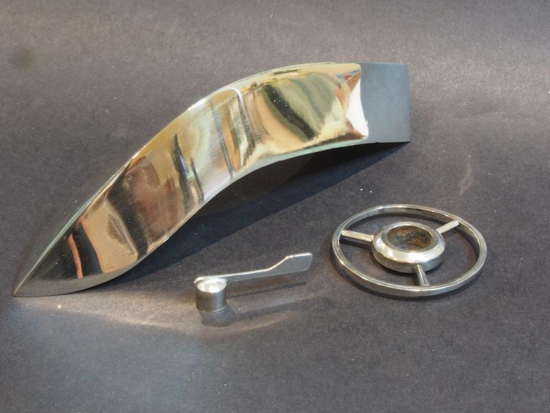
Finally got around to completing the wheel today. I painted the hub assembly, trim piece and wheel rim with Vallejo Ivory, sprayed through the airbrush, while the Horn Ring and Throttle Lever are chrome plated. After test fitting all parts, I glued them in place with epoxy – no going back now! Here is the completed wheel and steering shaft assembly: And another view: And here it is side-by-side with the kit-provided part: And finally, here are a few “glam” shots showing it in place in the boat: I decided I wasn’t happy with the cutwater, so have re-made it this weekend as well. Pics to follow once chrome plating is complete.
- 339 replies
-
- 31
-
-
- dumas
- Chris-Craft
- (and 3 more)
-
I'm in too! Just enough room left in the front row.
- 287 replies
-
- 3
-
-
- michelangelo
- ocean liner
- (and 1 more)
-
Are you an NRG Member???
gjdale replied to Chuck's topic in Using the MSW forum - **NO MODELING CONTENT IN THIS SUB-FORUM**
Thanks Kurt, In the meantime, I just heard back from Mary with my member number. -
Are you an NRG Member???
gjdale replied to Chuck's topic in Using the MSW forum - **NO MODELING CONTENT IN THIS SUB-FORUM**
Thanks Kurt, With no disrespect intended, and at the risk of sounding belligerent, it seems kinda weird that I can't find my membership number when logged in to the site...... that would seem to be a fairly basic piece of information..... I've sent an email as suggested, but should I have to? -
Well done on getting the log back up B.E. Perhaps she should be re-named HMS Phoenix!
- 366 replies
-
- 3
-
-
- pegasus
- victory models
- (and 2 more)
-
Are you an NRG Member???
gjdale replied to Chuck's topic in Using the MSW forum - **NO MODELING CONTENT IN THIS SUB-FORUM**
For those trying to find their NRG member number, and who like me had thrown out the packaging and secretary's letter already, I was able to go into the NRG Store and find it (I think). I selected the option to renew membership and (can't quite remember the exact sequence) it took me to a place where I could see when I last updated my membership (June last year). Their was a four digit reference number on this, so I'm assuming that is my membership number (at Ieast, I'm hoping it is!). Just thought this might help some others (if I'm correct in my assumption about the four digit number). -
Yes Jay, went the extra mile and bought the PM-V11 set. And yes, hand cutting dovetails is on the agenda.....
- 714 replies
-
- 4
-
-
- lady nelson
- victory models
- (and 1 more)
-
Thanks Chuck. You're right - deleting and re-doing a custom stream takes no time at all, so all good there. It takes a little playing around to understand some of the terminology in the filters, but a bit of trial and error gets you there. I'd noticed how you'd refined some of the other streams too. Might be worth mentioning, that once you've created a custom stream, if you click on the "tick" icon at the top of the page, the system adds a "permanent" short cut to the desktop for you (at least, permanent until you uncheck the icon).
-
Chuck, I might be missing something here, but having successfully set up a custom stream following your instructions, I can't find a way to edit (and save) my selections. The pencil icon only allows you to edit the name of the stream. Am I missing something? Or do I need to delete it and start over?
-
Thanks Chuck - just what I was looking for!
-
Great work Jay. Those new tools look gorgeous - I'm drooling over my keyboard reading your posts! I've just received a set of Veritas chisels (for larger scale woodwork). They look and feel wonderful - cant wait to start using them.
- 714 replies
-
- 4
-
-
- lady nelson
- victory models
- (and 1 more)
-
Funnels look terrific Nils - up to your usual exceptional standard!
- 2,625 replies
-
- 4
-
-
- kaiser wilhelm der grosse
- passenger steamer
- (and 1 more)
-
Congratulations on a truly fine model John - the museum is lucky to have you!
- 745 replies
-
- 3
-
-
- francis pritt
- mission ship
- (and 1 more)
-
Jay, There are some tutorials on Spiling somewhere here that would be worth your while reviewing. Essentially, tapering and bevelling really only account for two dimensions. Spiling takes into account the curve in the third dimension. That means that your planks will actually be curved when looked at laid flat on the table, but will appear straight (ish) as they follow the curve of the hull. Hope that makes sense.
- 714 replies
-
- 5
-
-
- lady nelson
- victory models
- (and 1 more)
-
Neat idea Jay. It strikes me that small pieces of sandpaper could be used as an alternative to file pieces - maybe a little cheaper in the long run
- 714 replies
-
- 4
-
-
- lady nelson
- victory models
- (and 1 more)
-
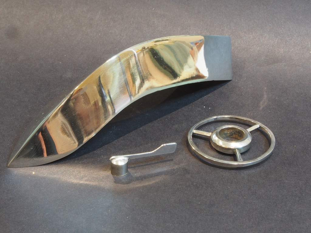
Thanks Slog, Mobbsie and Popeye, and also to all the "likes". Only a minor update today - have been distracted with other activities lately, and the last couple of days have been over 40 degrees C, so not a lot of energy for anything! But we have made some progress nevertheless. Chrome Plating - First Adventures To complete both the Wheel assembly and the Cutwater, some chrome plating was called for. Following the lead of others over on the RC Groups forum, I acquired a Caswell Chrome Plating Kit. It was relatively inexpensive and, as it turned out, quite easy to use. The kit consists of a small transformer with two leads extending from it. The black lead has an alligator clip attached and this gets attached to the part being plated. The red lead plugs into a small wand that has its end wrapped in a bandage, and this is soaked in the plating solution and then rubbed onto the part. And then the magic happens. It’s as easy as that. Not much to show, as I didn’t take photos of the process. Here is the end result though (the camera is not kind – it looks a whole lot better at “normal” viewing distance). Mmmmmmm……shiny…….
- 339 replies
-
- 15
-
-
- dumas
- Chris-Craft
- (and 3 more)
-
Congratulations on completing a very fine model indeed Bob.
- 277 replies
-
- 1
-
-
- model shipways
- 18th century longboat
- (and 1 more)