gjdale
-
Posts
4,894 -
Joined
-
Last visited
Content Type
Profiles
Forums
Gallery
Events
Everything posted by gjdale
-
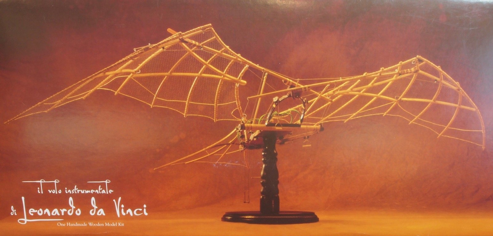
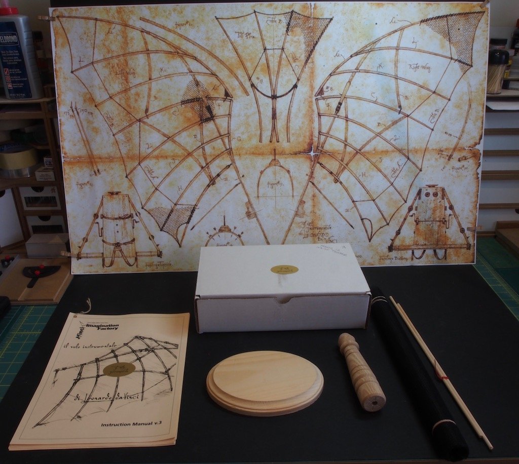
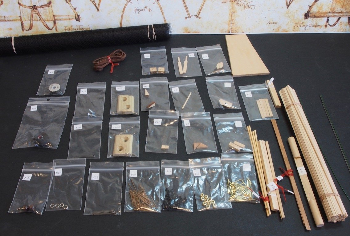
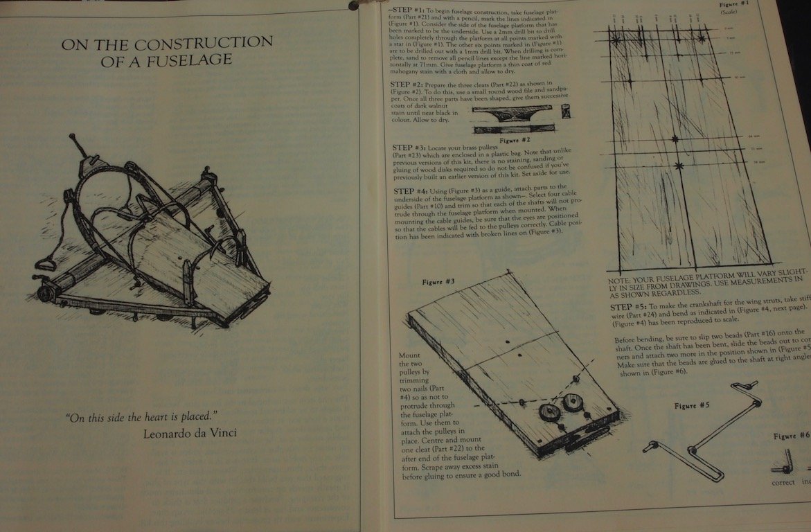
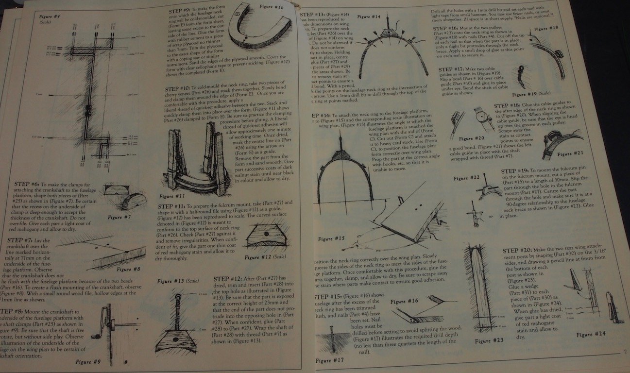
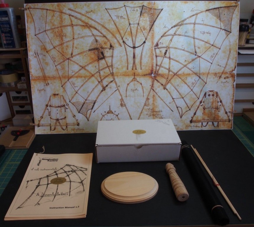
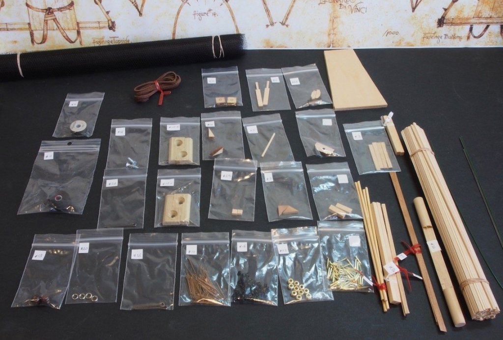
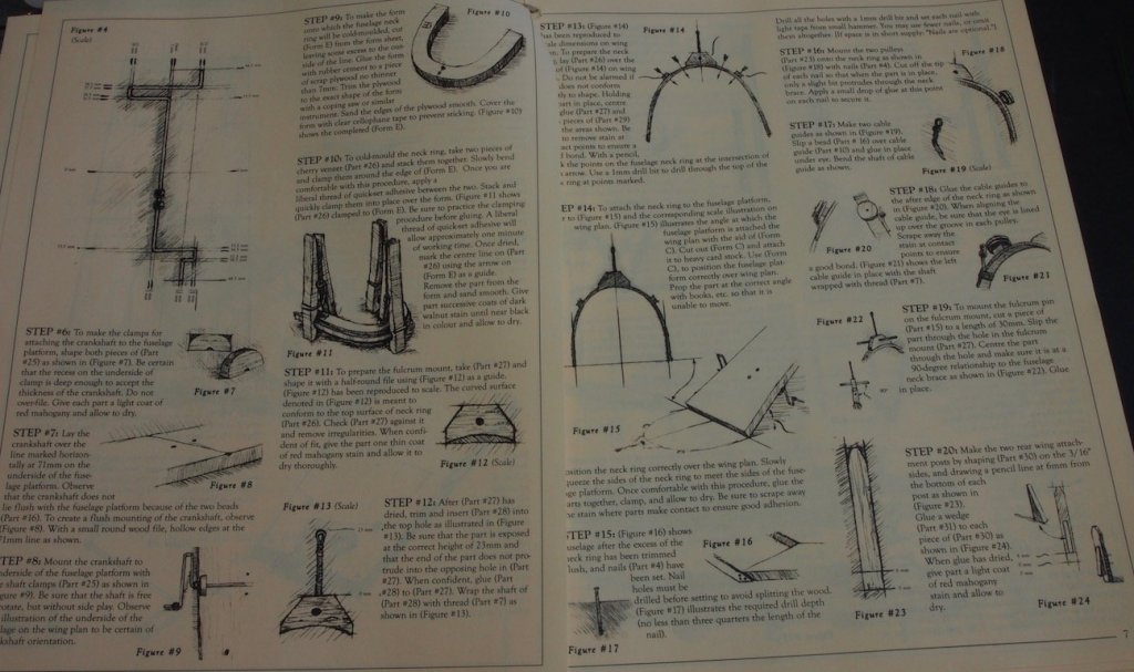
 This kit was a Christmas present from my wife in 2013. It has sat in the “stash” since then, calling to me occasionally. I originally came across this on the previous MSW site. We had recently returned from a European holiday where Da Vinci’s art had featured quite strongly, so naturally I was drawn to this kit. The kit is produced by The Imagination Factory, but a recent check of their website (www.davincistore.com) site suggests that the kit is either temporarily or permanently unavailable. The kit was designed by artist Robert Coyle, based on his extensive research of Da Vinci’s drawings. What’s in the box? The kit box is quite large, but there is a lot a free space inside. It seems that the box length was determined by the lithograph wing plan, which is both required for building, and a lovely piece of art in its own right. So the main box contained the lithograph, some tulle-type of fabric (for the wings), a couple of longer dowels (also part of the wings), the display base (in two parts), the instruction manual and a much smaller box containing the majority of the kit parts. Opening the smaller box, we find most of the parts ‘carded’ with a small drawing to help identify part numbers. I immediately re-packaged all of the small parts into labelled zip-lock bags. The wood appears to be mainly bass wood, and although it appears to be reasonable quality, I had made up my mind that I would replace all of the kit-provided wood with a mixture of Boxwood, Cherry, and Walnut, all of which I ordered from Jeff Hayes at Hobbymill before he closed the business. The plan is to use the pre-cut parts as templates to make my own from the new wood. The instruction manual is interesting in that all of the drawings look like they are hand-drawn. It really adds a very nice artistic flair to the entire kit. Here’s a couple of pictures from the manual: That’s about as far as I got today. Building will commence in earnest shortly, so stay tuned….


- 68 replies
-
- 21
-

-
Looking good Slog - your care and effort is really paying off.
- 244 replies
-
- 5
-
-
- borodino
- dom bumagi
- (and 1 more)
-
Nice to see back in the shipyard Hamilton. Glad to hear the surgery was a success and hope the recovery continues to go well for you. Don't get lazy with the exercises either - they will make a huge difference in the long run!
-
Sorry to hear you've been under the weather Danny - there's been some really nasty flu bugs going around this year. Glad to hear you're on the mend though. And the build is looking outstanding!
- 295 replies
-
- 2
-
-
- amatsukaze
- halinski
- (and 2 more)
-
Doug, Sherline also offer a 10,000 rpm pulley upgrade kit - easy to install. So you can always add that later on if you feel you need it.
-
Nice to see you back Adrieke - welcome home!
-
Great to see you back Mobbsie my friend! Pav - if the boat has been glued in with PVA, then some judicious application of isopropyl alcohol should help you to remove it.
- 129 replies
-
- 6
-
-
- armed launch
- panart
- (and 1 more)
-
Hey Mobbsie - nice to see you back here my friend, and thanks for the kind comments. 'bout time we saw some more sawdust from you ain't it? 😉
- 339 replies
-
- 3
-
-
- dumas
- Chris-Craft
- (and 3 more)
-
Thanks very much Slog, Bob, Don, Ken, Sjors and Mark, and all the "likes". I hope to take a short video when we do eventually get to sea trials.
- 339 replies
-
- 5
-
-
- dumas
- Chris-Craft
- (and 3 more)
-
Thanks very much Danny. Hadn't thought about the show. Hmmmmmmmm........ maybe..........
- 339 replies
-
- 4
-
-
- dumas
- Chris-Craft
- (and 3 more)
-
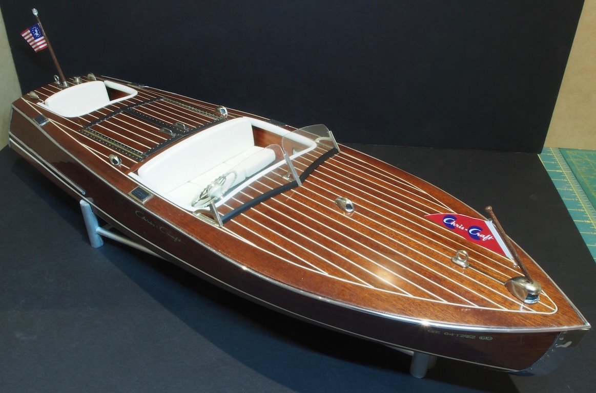
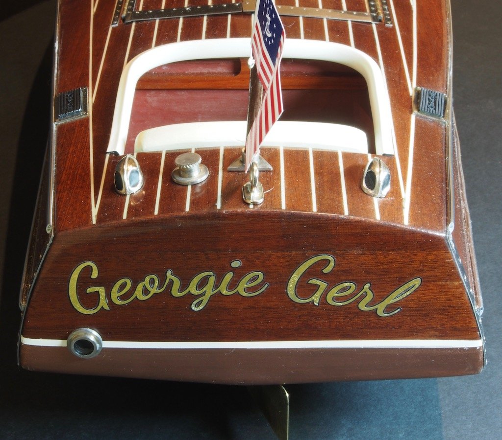
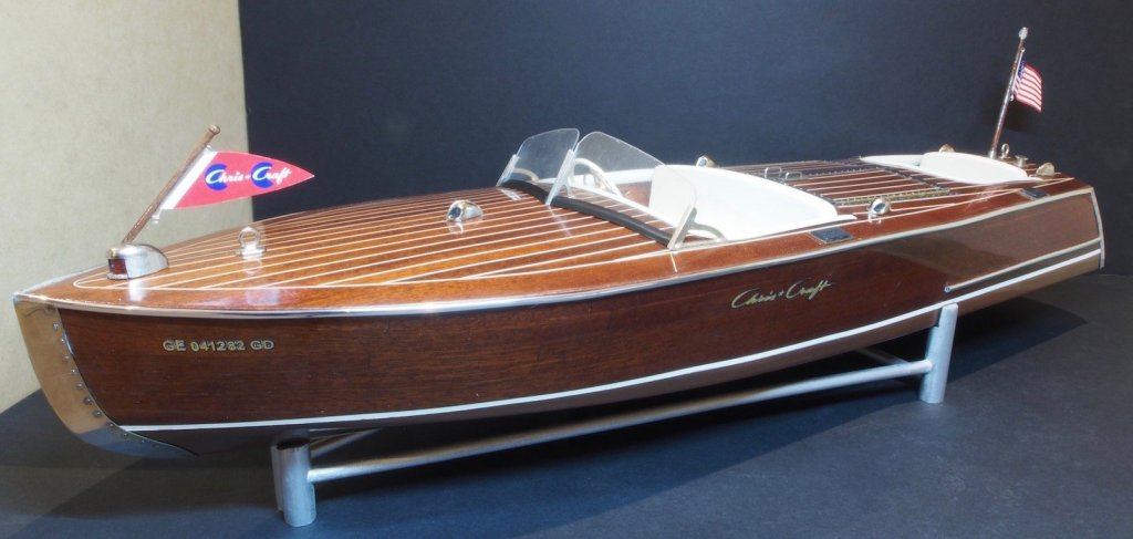
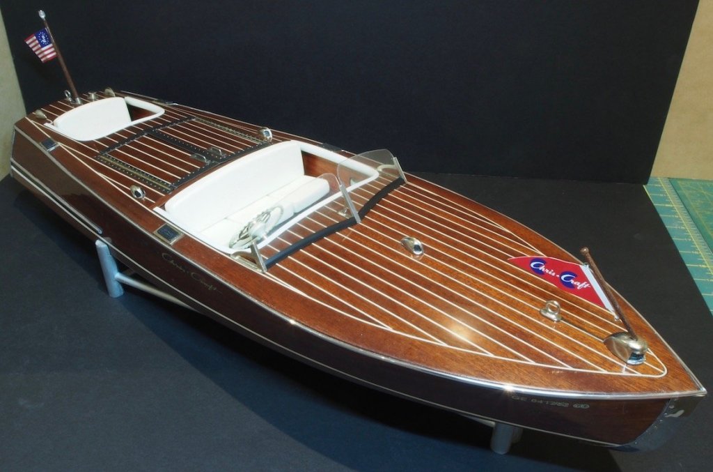
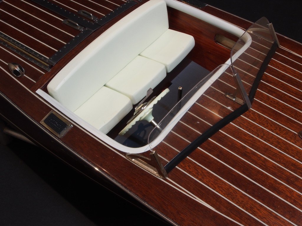
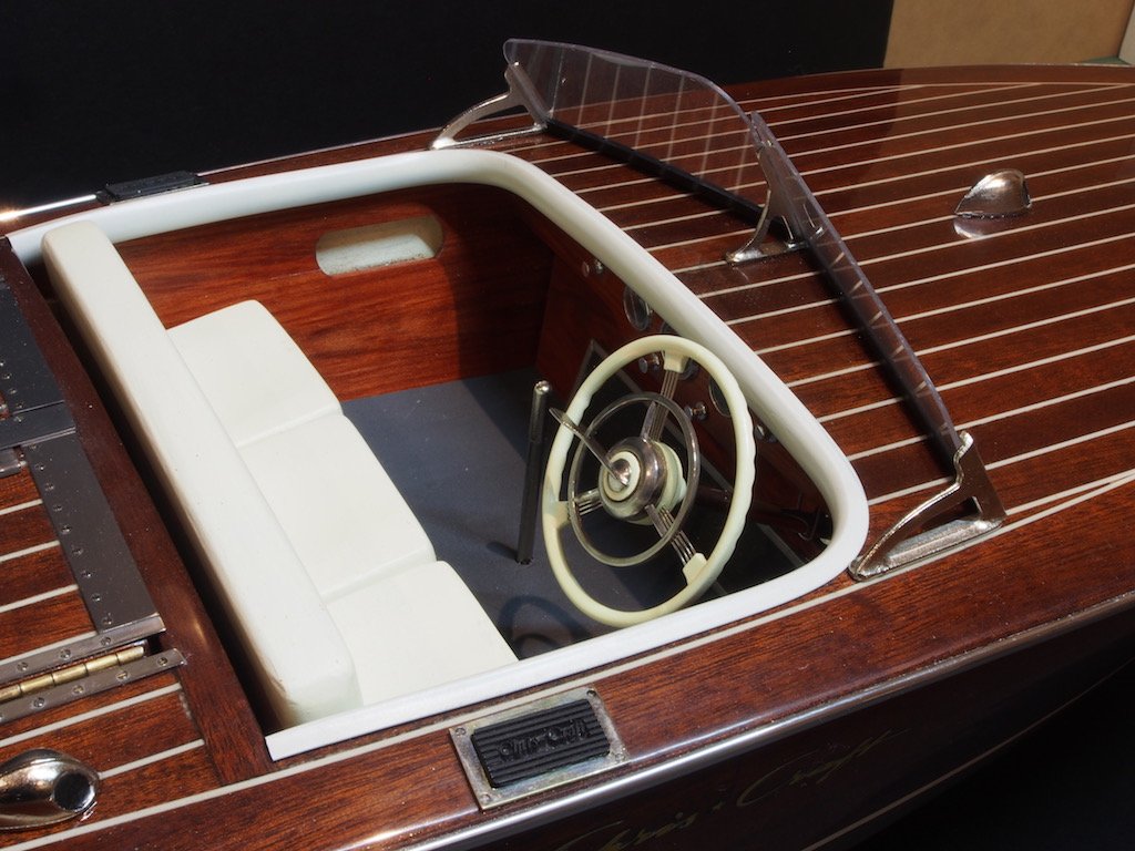
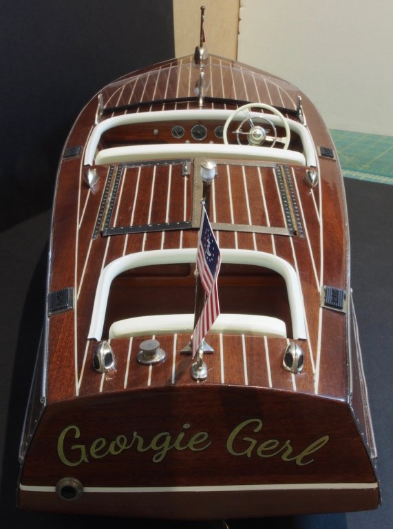
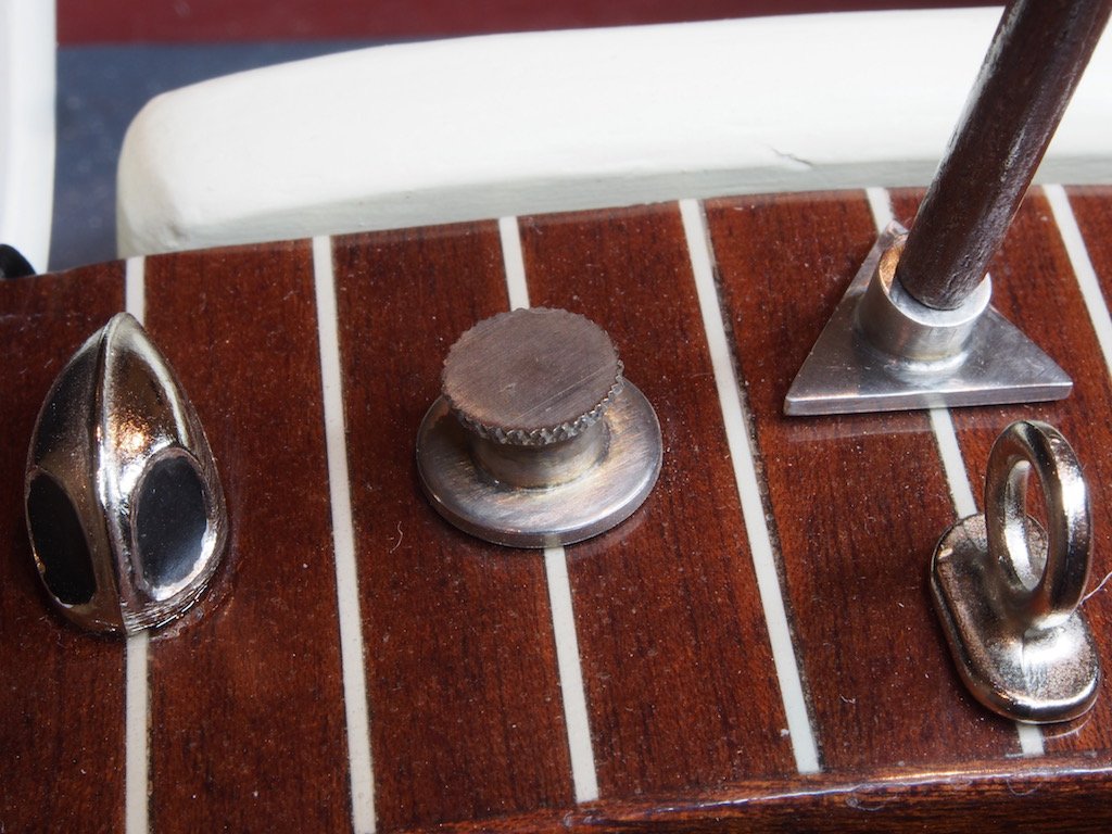
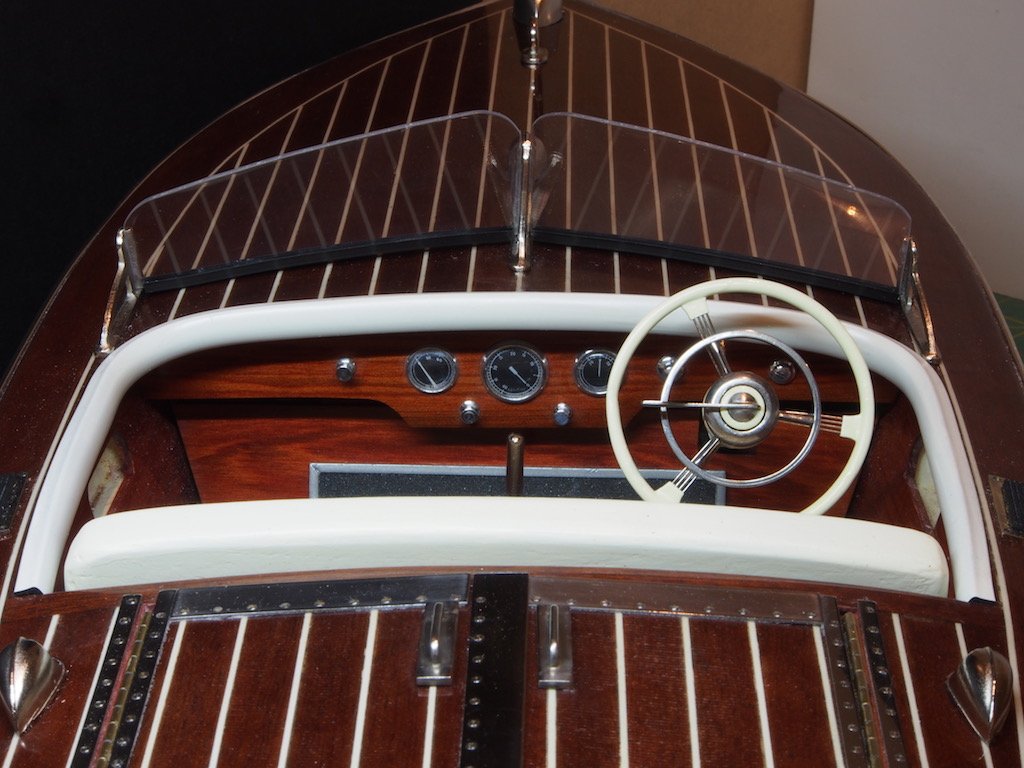
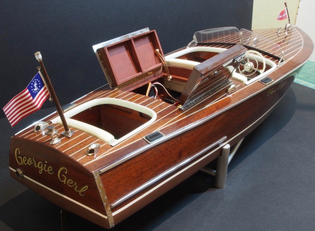
Thanks for all the kind comments and likes folks. It seems a long time since the last update, but progress has been steady with all of the final fittings. I re-made a number of the fittings: The Exhaust, Gas Cap, Rear Flag Pole Base, and Hatch Cover Handles. With all of these, the castings were useable, but the time and effort to clean up the flash and then polish and potentially re-plate them meant that it was easier to re-make them. All were made from brass and chrome plated on completion. I added some knurling to the lid of the Gas Cap just for some extra interest (and because I hadn’t used the knurling tool on my lathe yet). The Fwd and Aft Flagpoles were turned on the lathe from walnut stock, after first drilling them to receive lighting wires and/or brass locator pins. Another fairly straight forward exercise that posed no particular problems. Both the flagpoles have been made removable to provide some protection during transit to and from the lake. I had ordered some replacement cloth flags from BECC but was a little disappointed in the product when they arrived – they are only printed on one side. So I used the kit provided flags instead and the “client” is happy with these. Once the final soldering of the lighting wires was completed and tested, it was time to present the completed boat to the “client” for provisional acceptance. She was delighted with the final product. All that remains now is sea trials prior to final acceptance. Given that a successful float test has already been completed in the domestic testing facility, sea trials may need to wait until the weather warms up a bit as the manual recovery system says he doesn’t wasn’t to go swimming just yet! With that, I’m calling DONE! Here are a few glam shots of the final product.

- 339 replies
-
- 24
-
-
- dumas
- Chris-Craft
- (and 3 more)
-
Hey Bill - so glad to see you back! Sorry to hear the cabinet/furniture shop didn't work out but pleased to hear you're back doing something else you love - helping other people. Can't wait to see you making sawdust again. Welcome home, my friend.
-
Congratulations on completing your first build. You can be justifiably proud of a fine model - well done!
- 164 replies
-
- 3
-
-
- model shipways
- armed virginia sloop
- (and 2 more)
-
Sorry to hear you've been ill Mike, but glad to hear you're on the mend and will be back at the bench soon.
- 146 replies
-
- 2
-
-
- dumas
- Chris-Craft Commander Express
- (and 2 more)
-
Congratulations Nils on a stunning model. It has been a real joy to follow your progress for the last 2+ years. I look forward to following your next build.
- 2,625 replies
-
- 6
-
-
- kaiser wilhelm der grosse
- passenger steamer
- (and 1 more)
-
Hi Kevin, For RC advice, this forum is very good: https://www.rcgroups.com/scale-boats-55/ Be careful though, you'll see many other things to distract you!
-
Mark, Sorry to hijack to your thread, but all this talk of Death Star and I couldn't resist.........
-
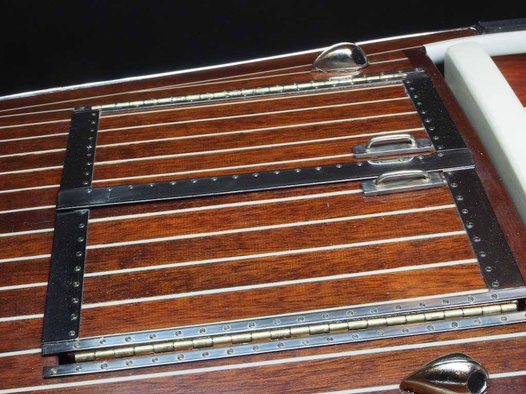
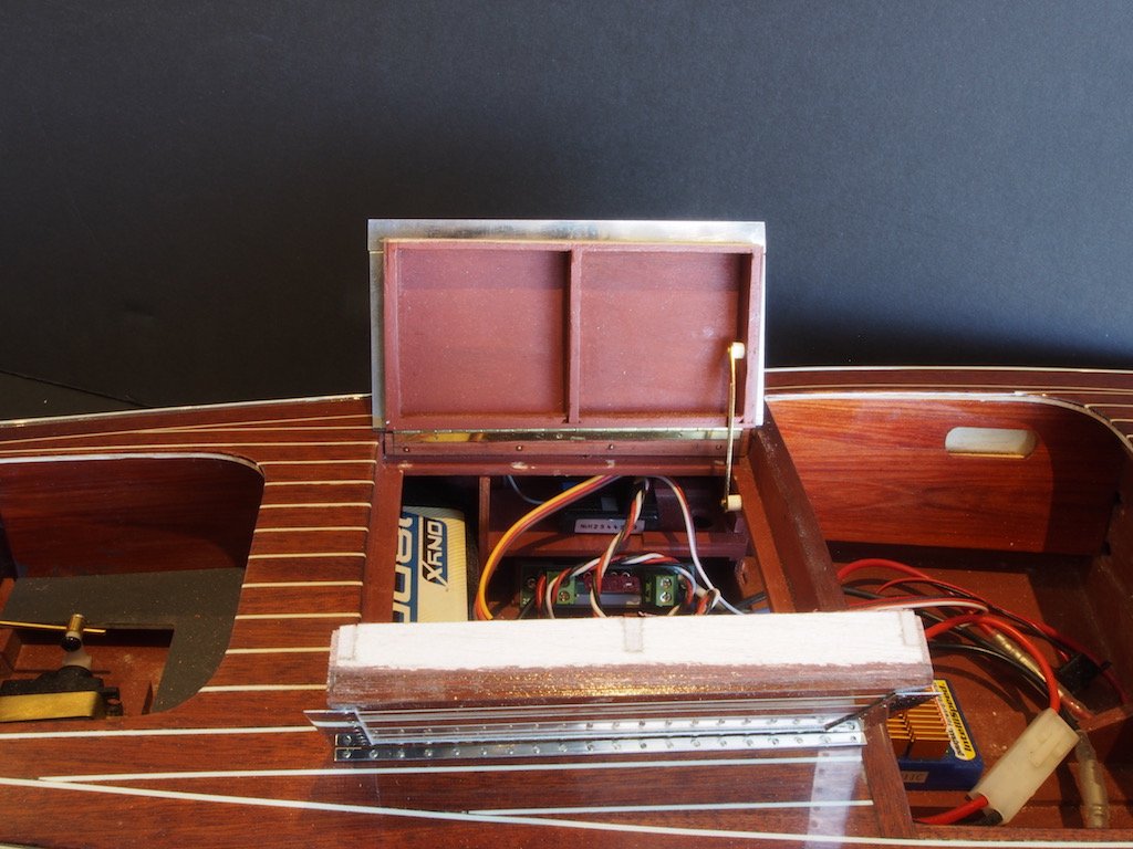
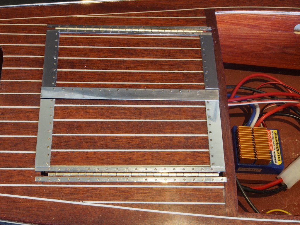
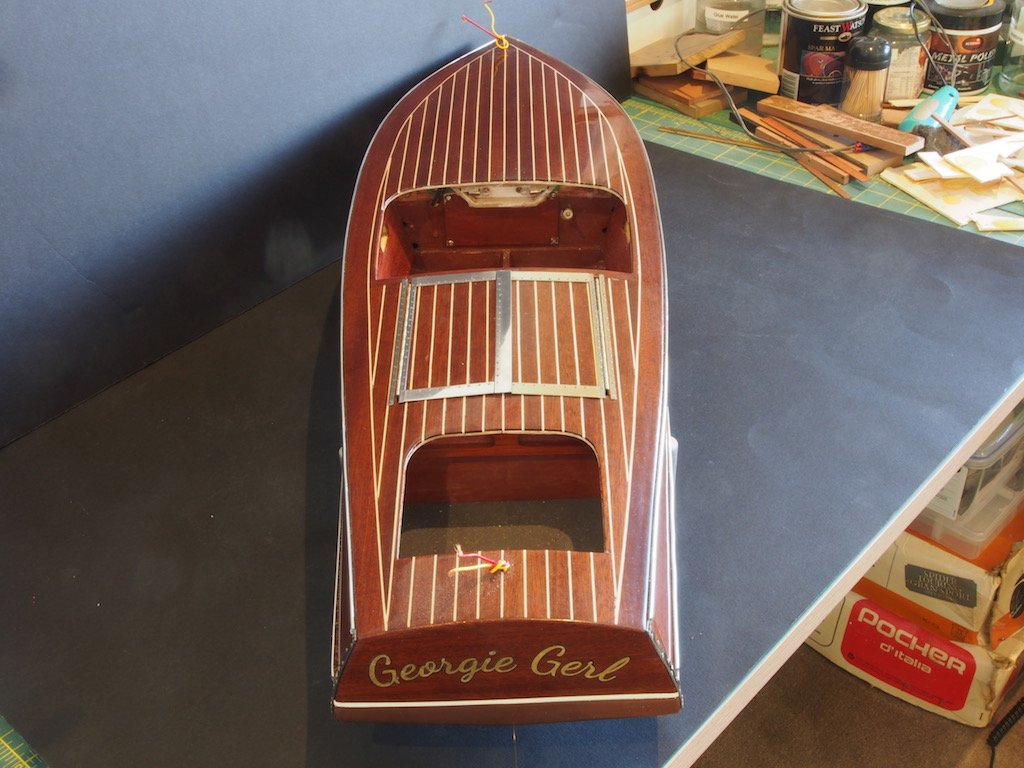
Thanks Hamilton and welcome to the build - never too late for this party! Another minor update of sorts. I had to re-visit the installation of the Engine Hatches as the hinge mounting failed. The hinges were initially epoxied to the hatches and then attached to the hatch frame with attachment tape (a type of double sided tape). The tape gave way, so I had to reconsider the whole setup. In the end, I made two shims from some scrap 3/64” thick Red-heart and epoxied these to the outboard side of the hinge flap. The shims were then epoxied to the hatch frame and held in place with map pins while the glue set. Once the pins were removed, I filled the holes with a few brass nails. Of course, the shims added just enough width to the hatch assemblies to prevent them from closing properly, so I then had to sand down the mating faces until the hatch would open and close properly. The photo below shows the completed “fix”, although touch up painting is still required. I was then able to drill the holes for the 000-120 screws, which were then individually epoxied in place…..all 130 of them. The heads of the screws were also aligned to the long axis of the trim piece, so that fore/aft trim pieces had screw heads aligned fore/aft, and athwartships trim pieces had screw heads aligned athwartships. It’s a little hard to see in the photo, but trust me…they are aligned! And here’s an overall shot for perspective:
- 339 replies
-
- 16
-
-
- dumas
- Chris-Craft
- (and 3 more)
-
Sorry to hear about your injury Hamilton - hope all goes well with recovery. Nice to see you back working on Bluenose.