gjdale
-
Posts
4,894 -
Joined
-
Last visited
Content Type
Profiles
Forums
Gallery
Events
Everything posted by gjdale
-
 Beautiful job Augie. She really is starting to look as flash as a rat with a gold tooth!
- 2,191 replies
-
- 3
-

-
- confederacy
- Model Shipways
- (and 1 more)
-
Yup, wot they said!!! Reading your updates never fails to put a smile on my dial Danny!
-
Nice to see an update Sjors, she's looking magnificent (with or without dust )
- 1,616 replies
-
- 2
-
-
- caldercraft
- agamemnon
- (and 1 more)
-
I'll be pulling up a front row seat as well to watch you work the "Mobbsie Magic" on this one!
- 62 replies
-
- 2
-
-
- harwich bawley
- fishing boat
- (and 2 more)
-
Many thanks for all the well wishes guys. A quick update - yes, from my hospital bed! Everything went well today - was in recovery by 0930 and in own room from 1300. Doc has visited and is well pleased. Physio have been and had me up standing and walking up and down on the spot already. Nursing staff all excellent. Oh, and some real quality pharmaceuticals too! Food has been excellent and I've just had the worlds longest pee (one litre's worth), which I proudly delivered standing up!!! (I know - it's a real boy thing!) Doc says hopefully released on parole over the weekend, or Monday at latest, all going well.
- 456 replies
-
- 13
-
-
- finished
- bomb ketch
- (and 2 more)
-
If we learn from our mistakes, I must be pretty smart now.
gjdale replied to skipper1947's topic in Wood ship model kits
My horse just returned from his gallop and reports that you're model looks great, even without his blinkers on! There are many who would be well satisfied to have made your "mistakes", Skip. If the number of mistakes we make is a measure of our learning, then this is a pretty darned erudite group here! I just had three goes at making the shell room on my model, before being satisfied with the results. It's a very well-educated shell room now! -
Thanks everyone for the kind comments and all the likes. I had hoped to post a bit more of an update tonight but a couple of things got in the way............ Firstly, having proudly displayed all of my component parts in my last update, when I went to assemble them I found some small but significant errors in the milling of the shell room pillars. Long story short, I didn't take enough care in setting up the mill and because I cut all 18 pillars in one continuous cut, there were enough differences between one end and the other of the cutting line, that when assembled the bomb racks between the pillars looked like they'd been for a run ashore on pay day. That then gave me the impetus to also re-make the floor support beams - those incorrectly drilled holes were still bugging me. So I re-made everything...........................................twice! Yep, managed to bugger up both the milling and the floor beams on the second attempt. Fortunately, it was a long weekend and rainy - no other "distractions" in sight! So after measuring 37 times, and aligning the mill to within a cat's whisker of its life, I went for attempt number three. What was that about "the third time is the charm"? All I can say is that Jeff Hayes (of HobbyMill) must have believed in this as he supplied enough raw material to allow a third attempt! Thanks Jeff!!! Don't know what I would have done if I'd botched it a third time. Anyway, a test fit of all parts revealed a good match all round. I then needed to await delivery of my new "bombs", which arrived today. The size looks right, but they have a shiny finish, which I will probably spray with Dullcote before using. So unfortunately, no photos for now. I will take a few during the final assembly and finishing process and post with my next update. That, however, will be a few weeks in coming as I've been consigned to the knackers yard to get some replacement body parts. I'm going into hospital tomorrow morning for a hip replacement operation. I had the first one done about five years ago, so I'm no stranger to the procedure, or the recovery process. I do know two things for sure. Firstly, I'll be in less pain afterwards than I am now, and secondly, I'll be enjoying some quality pharmaceuticals for a little while! That of course means no model building - unless of course you were interested in seeing some rather unique maritime interpretations.................. I hope to be back in the shipyard in a limited capacity in 2-4 weeks, but will have to await both surgeon and Admirals approval first. And of course, you just know which of those is going to be the more difficult to obtain!!! In the meantime, I shall continue to live vicariously through all of your logs.
- 456 replies
-
- 9
-
-
- finished
- bomb ketch
- (and 2 more)
-
Hi Ben, It depends on the look/feel you want to achieve. If you want a very smooth and/or polished look on the unplanked area, then work down/up (?) to a much finer grit (say, 600). You'll find that once you've got the shape faired properly with coarser grit, the following grits will be much easier as they aren't forming the shape - they're just removing the scratches from the previous grit. Personally, I'd go to 220 where you're gluing planks, and 600 for the unplanked area - but in the end, it comes down to your own preference.
-
Congratulations on a very fine build Carl. What's next (after the Admiral's "honey-do" list that is)?
-
Nice to see you back in the shipyard Wayne. I look forward to more progress on this lovely little model.
-
Thanks very much Marc and Boyd. The reason there hasn't been an update in a while is that I've been sorting out plans for running gear and electrics/electronics, inlcuding making a working steering wheel, and lights that can be switched on remotely. I've been guided by some very helpful folks on the RC Groups forum, as well as by an exceptionally helpful guy who owns the last remaining real hobby shop in captivity here in Canberra. Consequently I've been slowly acquiring a variety of additional bits and pieces, and as Boyd correctly points out, I need to sort out their positioning in the boat before restricting access. I received the last of those components yesterday, so should be right to proceed. All I need now is that other priceless commodity - time!
- 339 replies
-
- 4
-
-
- dumas
- Chris-Craft
- (and 3 more)
-
Some more great work there Mobbsie - once again blazing the trail for the rest of the group coming along behind. Your other two builds might just slow you down enough for us to do a little catching up!
- 255 replies
-
- 3
-
-
- granado
- bomb ketch
- (and 2 more)
-
Ah! The problem with reality is that there's no background music............... Hope to see you back in the shipyard soon Andy.
- 382 replies
-
- 4
-
-
- stadacona
- sylvan scale models
- (and 1 more)
-
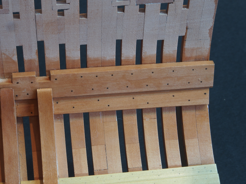
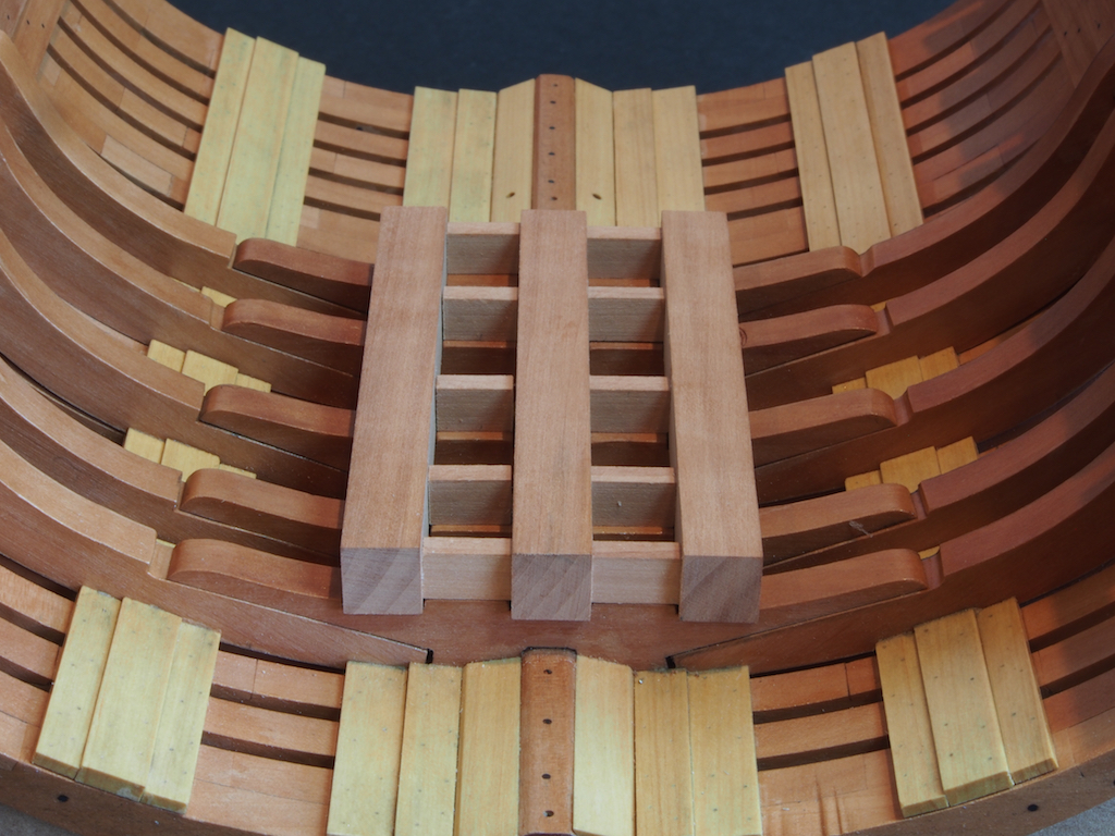
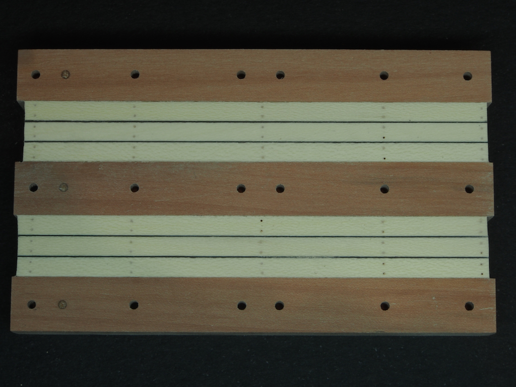
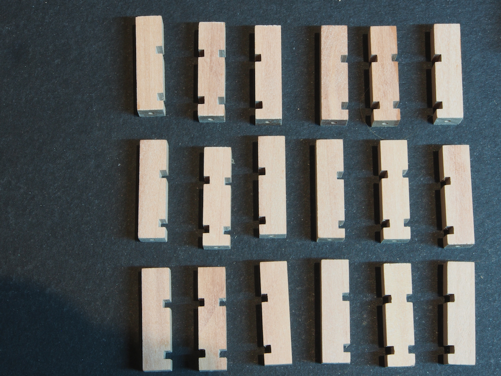
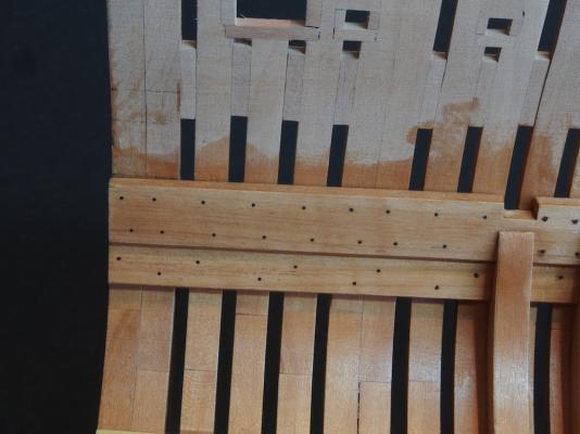
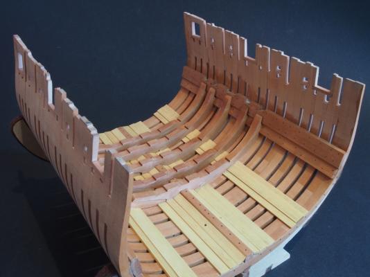
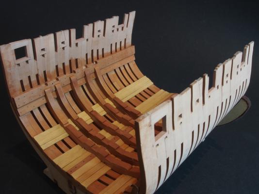
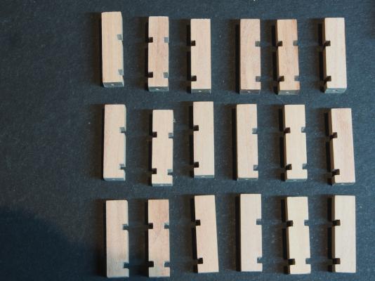
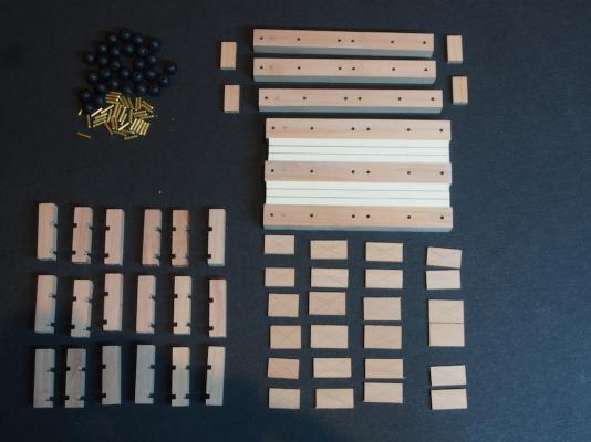
I've been away for the last couple of weeks, but did finally manage to get some shipyard time in this weekend. When last we met, I had decided to go ahead with the Deck Clamp Bolts. Here are a few pics of the final product – the pics appear somewhat streaky as the Wipe-on Poly was still wet when the pics were taken. With this job out of the way, it was time to make a start on construction of the Shell Room......... Shell Room Construction Construction of the Shell Room begins with the fitting of the lower support beams, made from 5/16” square Pear, across the Floor Riders, with cross beams added in situ to ensure a proper fit. Once the glue had dried, the frame assembly was removed from the model for further construction and fit-out. The next step was to install the deck planks. These are made from Holly, 1/16” x 1/8”. I opted to simulate caulking using black paper as I wanted to see how this would look, knowing that once the assembly was completed, this deck would hardly be visible. I also added treenails, using the drill and fill method as described previously. In the above photo, you may notice three filled holes towards the left hand end (one in each beam). This was where I incorrectly transferred one measurement before drilling. I have filled the incorrect holes with a mixture of Pear sawdust and diluted PVA. Once the assembly is complete, these will be barely visible, so I’m going to live with it. I've also just noticed that a couple of "treenails" in the Holly decking have come adrift and need replacing...... The pillars to support the shell racks were the next to be made. No particular rocket science here, but a great job for the Sherline Mill after cutting the blanks on the Byrnes saw. I constructed a small jig to hold all 18 pieces, then cut the dados (which are 2mm deep) in two passes of 1 mm each, using a 5/64” end mill cutter. The only issue I had in this job was caused by operator error when I failed to ensure that the cutter was securely held in the mill. The net result was that I destroyed half of my blanks in one pass. No biggie – just whipped up some more blanks on the Byrnes saw and replaced the duds. (Did I mention I love my Byrnes saw?.........and my Sherline Mill?) The pillars were also drilled in each end to take one end of a 1.5mm diameter brass locating pin (to match the holes drilled in the support beams). Finally, here is an overall shot of all the components of the shell room. The Shells themselves are ¼” diameter beads – they may be just a tad undersize, so I’m holding off on drilling out the shell racks until I find out whether I can source some slightly larger beads of the same type.


- 456 replies
-
- 22
-
-
- finished
- bomb ketch
- (and 2 more)
-
Nice work Ken - I just knew you'd be a natural in this medium!
- 440 replies
-
- 2
-
-
- niagara
- model shipways
- (and 1 more)
-
Great "how to" on the iron work Danny. And I guess a great "how to" on carving figureheads as well - ask Janos to do it! Seriously though, the figurehead looks great and is another example of this great community helping each other out. Kudos to Janos.
-
Great to see you back Paul. I look forward to the resumption of your magnificent build.
-
Lovely job on the yawl Ken. Looking forward to the next addition to the miniature fleet.
- 440 replies
-
- 1
-
-
- niagara
- model shipways
- (and 1 more)
-
You're off to a great start Ken - no surprise here!
- 440 replies
-
- 2
-
-
- niagara
- model shipways
- (and 1 more)
-
Lovely work Mobbsie. I can't wait to get back to the shipyard to catch up.
- 255 replies
-
- 1
-
-
- granado
- bomb ketch
- (and 2 more)
-
Great work Daniel - they look terrific.
-
Just lovely Bob. Up to your usual high standard I see!