gjdale
-
Posts
4,894 -
Joined
-
Last visited
Content Type
Profiles
Forums
Gallery
Events
Everything posted by gjdale
-
 Nice to see you back Bill. When are we going to see this and see that?
 -
Great work, as always, Mobbsie. Please keep blazing the trail for the rest of us - we'll catch up again eventually!
- 255 replies
-
- 1
-

-
- granado
- bomb ketch
- (and 2 more)
-
I have to agree with Kurt about Ken's book. It's a real beauty - both informative/instruructive, and a fabulous "coffee table" book for the pictures alone.
- 440 replies
-
- 2
-
-
- niagara
- model shipways
- (and 1 more)
-
Nice to see this lovely build underway again Wayne.
-
That's got to be the understatement of the year Harvey! That is WAY better than anything you could buy. Excellent work!
-
Wonderful work, as always, Bob.
-
Nicely done Jerry. Colour coding seems to make sense too.
-
That's looking really good Harvey!
-
I'm a little late to the party Nils, but this looks like it's going to be a real beauty. I'm in for the ride!
- 2,625 replies
-
- 3
-
-
- kaiser wilhelm der grosse
- passenger steamer
- (and 1 more)
-
Jerry, I seem to recall that Mobbsie built this model (might have been before the "great MSW crash"), and he used Celtic emblems (coats of arms?) for his shields - just to be a little different.
-
Great to see you having a go at scratch building the boats Harvey! Looks like you've made a good start there.
-
Glad to see you solved your soldering problem Stuart. The guard rails are looking good.
-
That looks terrific Jerry. Sorry, but I can't offer any advice re the shields. I'm sure that whatever you choose will look great.
-
Great work Augie - I can only echo everyone else's comments.
- 2,191 replies
-
- 2
-
-
- confederacy
- Model Shipways
- (and 1 more)
-
Congratulations on both milestones Joe! Your ship is looking superb. Hope you get to indulge yourself with many ship modelling goodies to celebrate the other milestone!
- 302 replies
-
- 2
-
-
- granado
- caldercraft
- (and 1 more)
-
Congratulations on completing the rigging Bob - a very satisfying milestone to reach. She looks absolutely superb. Why not add a scratch built boat? I'm sure that with the skills you've demonstrated many times over already, you would produce something worthy of the rest of your build. Just sayin'................
- 1,477 replies
-
- 1
-
-
- essex
- model shipways
- (and 1 more)
-
Of those currently available, the Caldercraft/Jotika is probably the best around right now. There are plenty of build logs here for this version, but check out the log by Gil Middleton for a real treat. A new Amati version is on the horizon (see the thread on "Amati and Chris Wotton" for a preview). She will be much bigger at 1:64 scale (Caldercraft is 1:72), but there is no indication yet on when the Amati version will become available.
-
Your research is paying off Ian. Perhaps the "oops" with the lathe was a sign that you were meant to scratch build a better, more accurate version. I can't wait to see your construction - I just know it will be educational!
-
Nice to see your fixes working so well Jesse - well done!
- 1,306 replies
-
- 4
-
-
- syren
- model shipways
- (and 1 more)
-
Very nice work on the sail Jerry. I take it that the Admiral has resumed ironing duties?
-
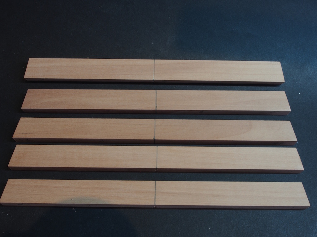
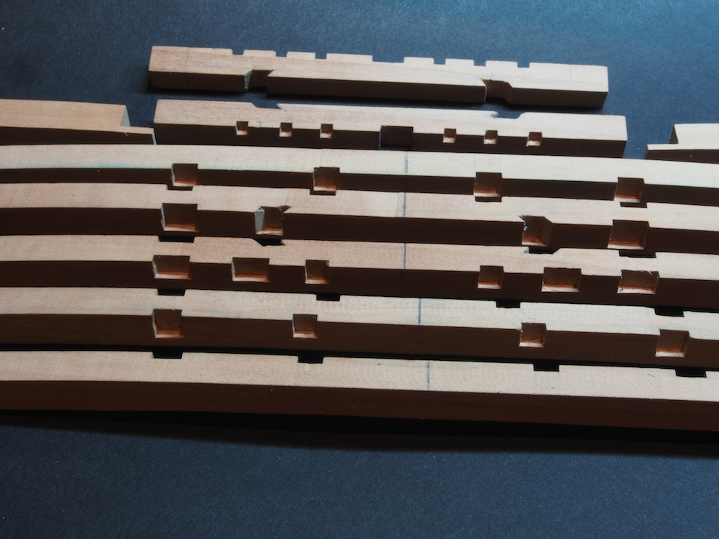
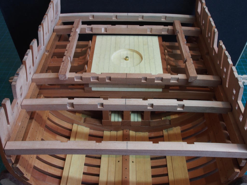
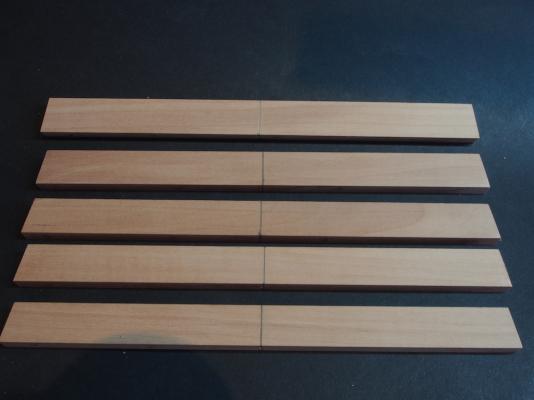
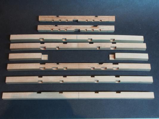
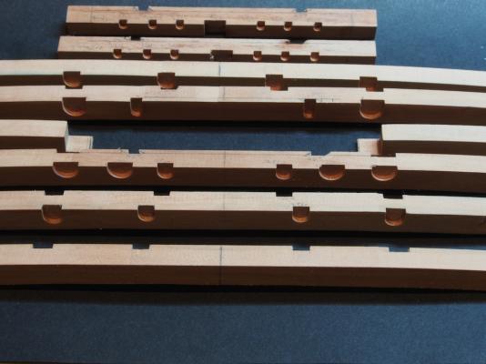
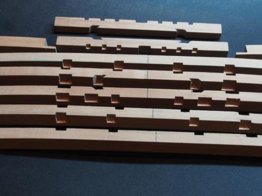
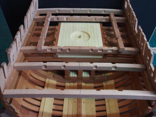
Thanks very much everyone for all the kind words and "likes". Jeff got back to me and confirmed that my observations about errors in the drawings were correct, and also confirmed that my corrections were….correct. Deck Beams I ummed and ahhed about the best way to prepare the Deck Beams with all of their various notches for receiving carlings, trimmer beams, beam arms etc. I then made the happy discovery that I possessed end mill cutters to exactly match these various sizes, so I decided to do as much of this work as possible on the mill in order to provide the maximum degree of accuracy and consistency. In order to do that, I needed to start with beam blanks that retained a “square” face for use as a reference plane for the milling work. So blanks were prepared to match each beam location, with just the ends angled to match the angle of the hull sides (10 degrees as it happens). Here are the beam blanks cut to size for each location and with a centre line marked for further reference: I forgot to take pictures of the next stage, but this consisted of sticking the beam patterns onto the fore and aft faces of the beam blanks, using the centreline and bottom edge as a common reference. The tops of the beam blanks were then cut down in height, using the mill, to align with the top of the pattern, while maintaining a parallel face with the bottoms. By further happy coincidence, or clever design by Jeff, all of the notches, regardless of depth (top to bottom), were set back a common distance into the beams (fore to aft, or aft to fore). By milling the notches with the blanks lying on their sides, I could then use a common depth of cut for all milling operations, and would therefore only have to be concerned with the “length” of the cut. That depth happened to be 1.5 mm. The length of cut varied with the size of timber to be accommodated, and was measured off the plans in imperial units (eg 7/32”) and then converted to decimal millimetres (eg 5.56mm) for application on the mill. It sounds complex, but was actually pretty easy. Once all of the milling was completed, the beams had their respective curvature applied while the paper patterns were still in place, using a combination of the spindle sander and disc sander to achieve the required curves. Here is what the beams looked like after all of these operations were completed and the residual paper patterns were removed: You can see in these photos, that the milling process leaves a rounded end. These had to be cleaned up and squared off using a chisel, which again seemed more daunting than it was in practice to achieve. The only real difficulty was in achieving the 45 degree angled notches to take the angled carlings that will eventually support the outside of the Mortar Pit. To achieve these, I used the mill to cut the “straight” bit in the middle, to provide a reference plane, and then completed the rest with a chisel. It was the 45 degree undercut that was particularly difficult – I’m sure there is an easier way than the method I used, but we got there in the end, and with no feeding of the scrap bin along the way! Here is a picture of the cleaned up joints: And finally, here is a picture of the completed beams dry-fitted in place. The “Trimmer Beams”, which will surround the Mortar Pit, are sitting loosely on top of the main deck beams. These will be trimmed to final length once the deck beams are permanently affixed. You can see in the photo that the centre lines of the beams seem to line up quite well, so the installation of the various carlings etc, should be relatively easy. Next up, cutting the various Hanging Knees, Lodging Knees, Beam Arms, and Carlings – all of which will also need to be notched. Progress may very well slow down from here as my period of convalescent leave ends this week and its back to work next week.
- 456 replies
-
- 24
-
-
- finished
- bomb ketch
- (and 2 more)
-
Nice work on the stanchions Mobbsie, and on the Black Pig. I hope your grand daughter was very pleased with it! Deck beams are looking good too - nice neat carpentry there my friend. Please tell me it's just the camera angle, but I can't see the 45 deg notches in the aft face of beam three...... Edit: On closer inspection, with glasses on, the 45 deg notches look fine! Sorry for the heart attack!
- 255 replies
-
- 2
-
-
- granado
- bomb ketch
- (and 2 more)