FriedClams
-
Posts
1,079 -
Joined
-
Last visited
Content Type
Profiles
Forums
Gallery
Events
Everything posted by FriedClams
-
 Just catching up on your build, and boy have you ever been busy! Wonderful work all around and I especially like the brass work. Excellent Nils. Gary
 -
Very nice progress Roger. Coming along very nicely. Gary
-
Excellent work OC. and very nice close-up photography as well. Gary
-
Congratulations Dan on another beautiful model. Your painting skills are just outstanding, and I thank you for sharing your techniques. Excellent! Gary
-
Wonderful model Glen - it turned out great! Congratulations on its completion. A very fun and entertaining log as well. Gary
- 290 replies
-
- 4
-

-

-
- Quinquereme
- Finished
- (and 1 more)
-
Roter Löwe 1597 by Ondras71
FriedClams replied to Ondras71's topic in - Build logs for subjects built 1501 - 1750
Clean and wonderful craftsmanship on that anchor, Ondras! Gary -
Fantastic job, Richard - it turned out beautiful. Congratulations on its completion! Gary
-
Just catching up, Eric and the progress on Peerless looks very nice indeed. Just as I knew it would. Gary
-
Brig Le FAVORI 1806 by KORTES - 1:55
FriedClams replied to KORTES's topic in - Build logs for subjects built 1801 - 1850
Spectacular progress, Alexander - really wonderful! Gary -
Wonderful brass work as always, Valeriy! Gary
-
Well done, Maurino! She looks great! Congrats on finishing her. Gary
-
Fantastic work, Grant! She turned out great. Congratulations on its completion. Gary
-
Excellent - another river boat and a great start, Eric. A terrific new workspace too! Will be following along with interest. Gary
-
The head repositioning is artistry, Marc. Not so much the mechanical act of it, but in visualizing what needed to be done. Gary
- 2,450 replies
-
- 3
-
-
-
- heller
- soleil royal
- (and 9 more)
-
If you haven't already, check your local hardware/building supply outlets as this sort of tape is often used on sheet metal ductwork to prevent air leaks. Varying widths and possibly thicknesses. Excellent (and fast) progress on your model, Nils! Gary
-
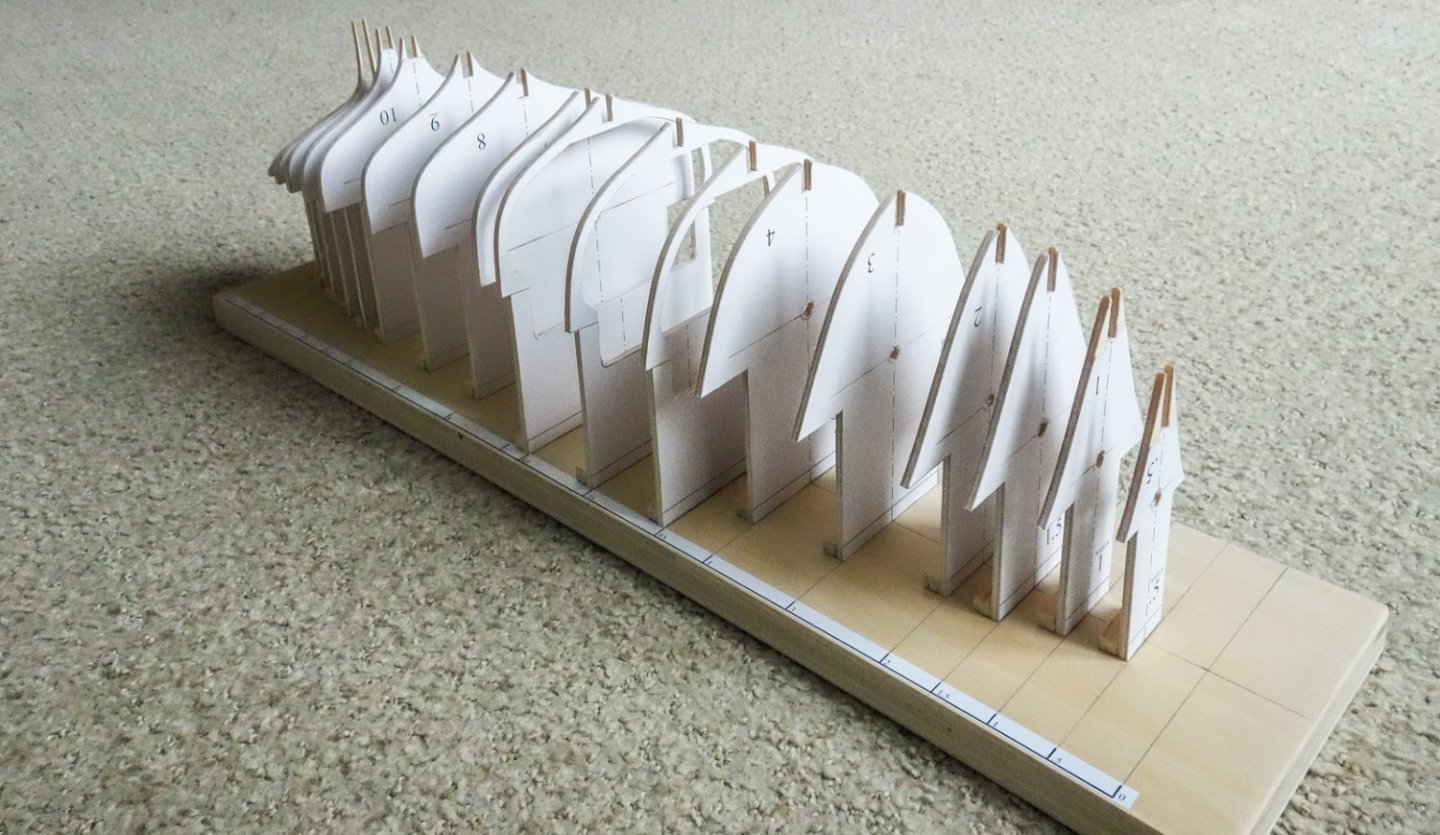
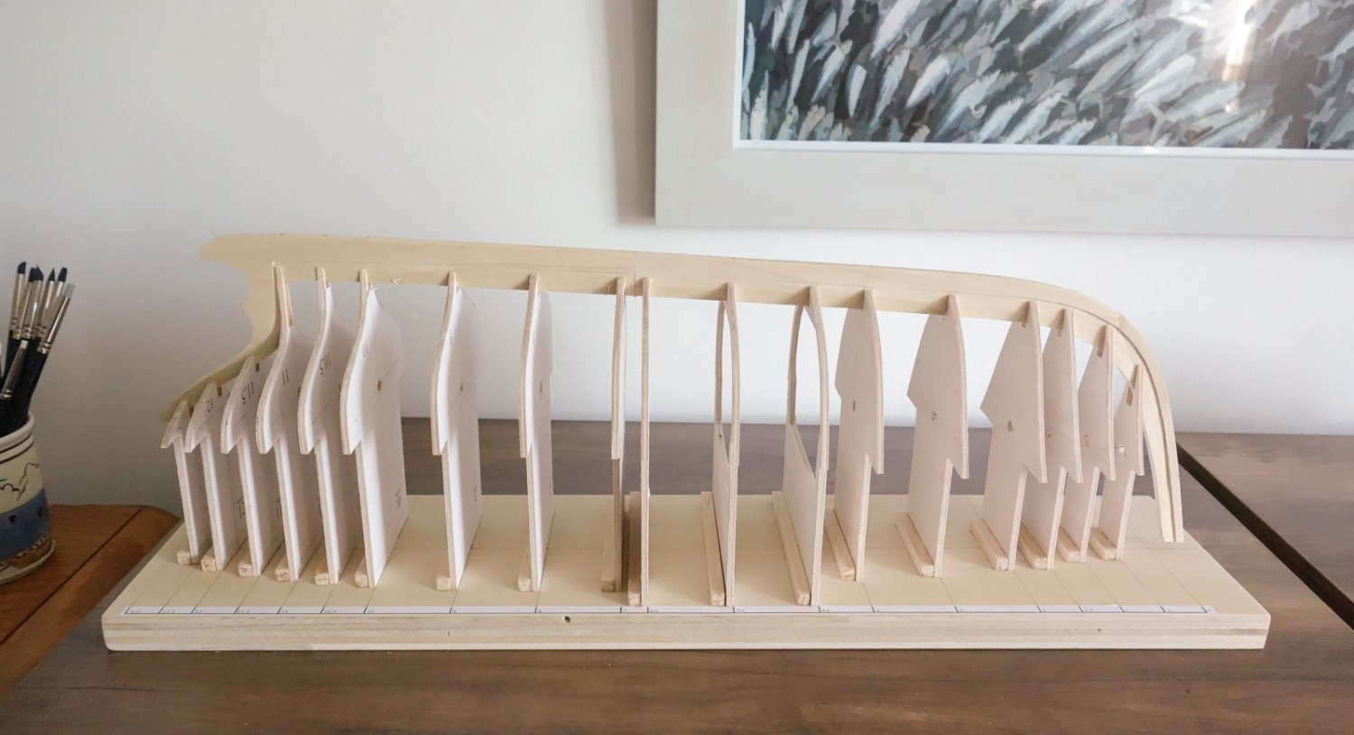
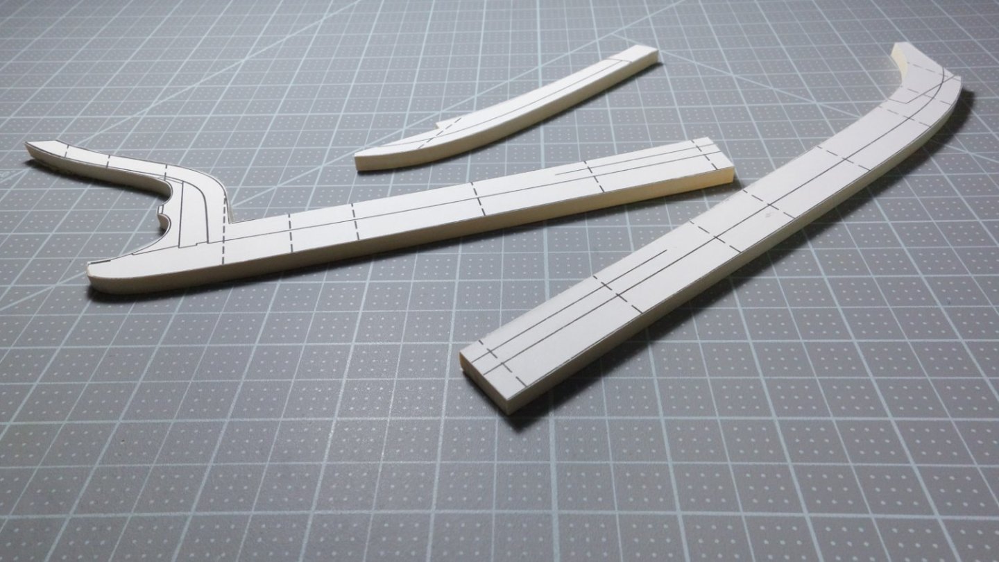
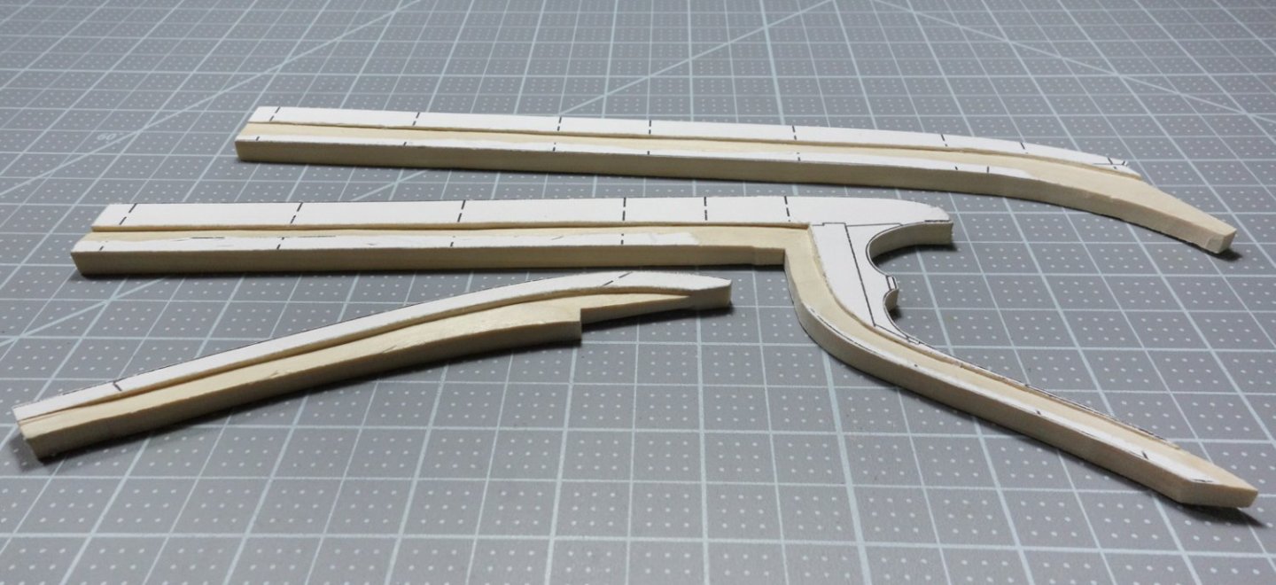
Greetings, Here's the current state of the model. The backbone drawing template was printed out in three sections onto full sheet label paper. The wood for the backbone is poplar and was cut to the required thickness using my full sized table saw. The templates were affixed to the poplar and cut out with a scroll saw. The rabbet was then carved into both sides. Below, the backbone is sitting temporarily on the station forms, waiting to be permanently attached. This model is being placed on temporary hold and it will be some time before I post again. I thank all of you for your interest in it and I hope to report some progress by the end of the year. Thanks. Stay well. Gary

-
A great start to another creative and interesting build, Glen! Looking forward to following along. Gary
- 290 replies
-
- 3
-
-
- Quinquereme
- Finished
- (and 1 more)
-
Sad to hear of your heart attack and so glad to hear of your recovery, Michael. It's great to see (and marvel) at your wonderful work once again. You have been missed. Welcome back. Gary
-
Nicely done, Mark - she looks great! Congratulations on completing her. Gary
- 505 replies
-
- 6
-
-
-
- vanguard models
- Sphinx
- (and 1 more)
-
Just went through your log and what an amazing build. Superb work, congrats on finishing her. Gary
-
Another miniature marvel in progress. Good to hear from you, Patrick. Gary
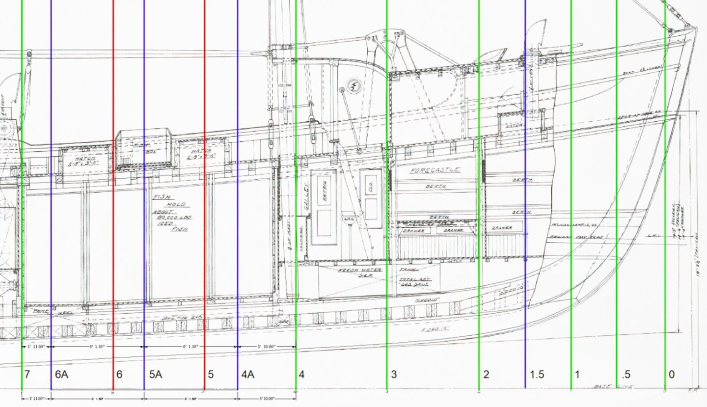
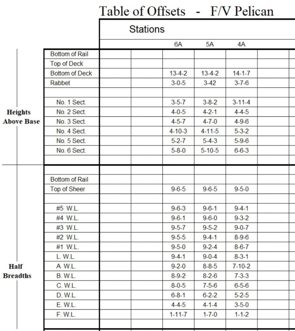
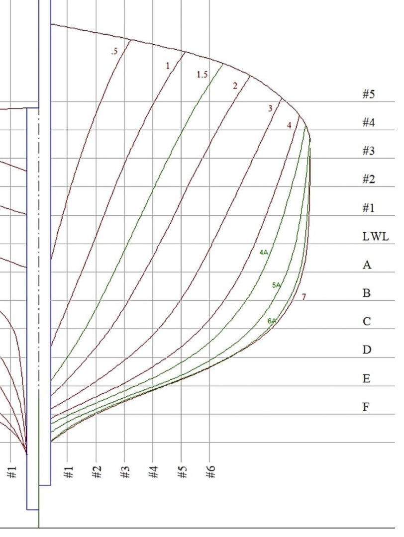
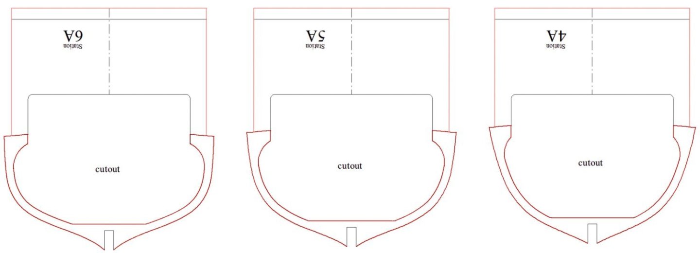
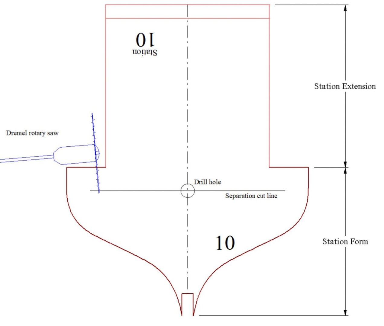
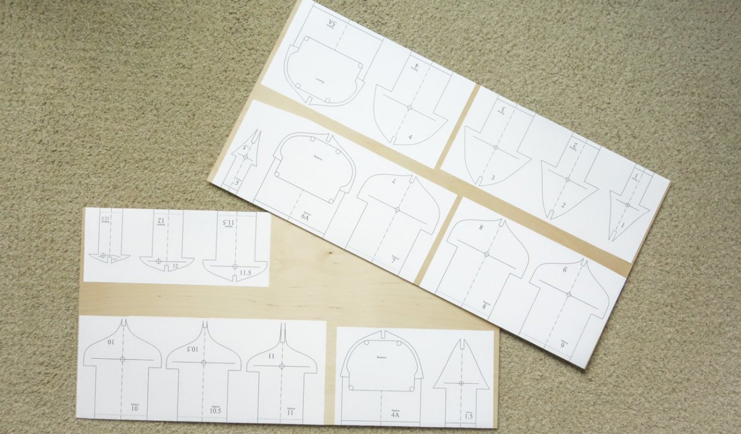
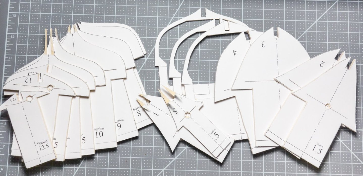
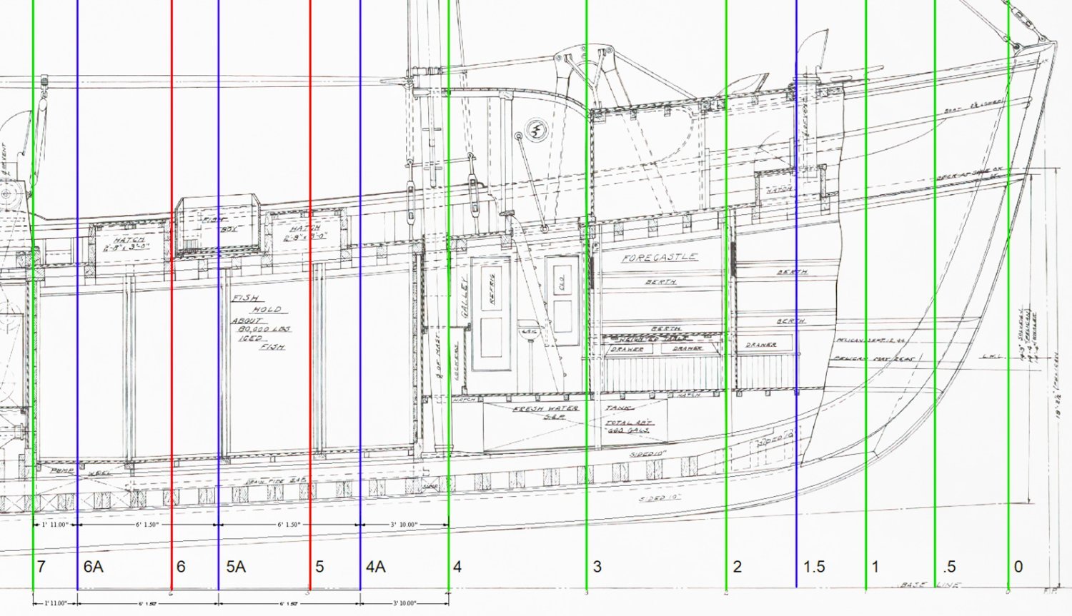
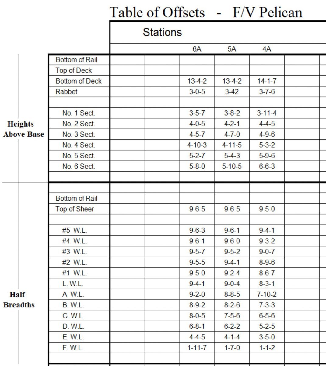
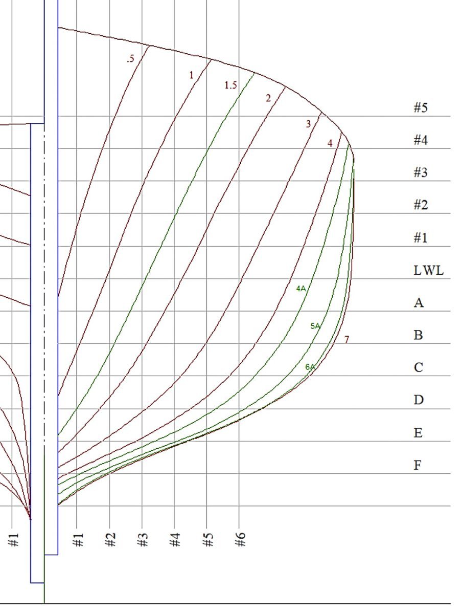
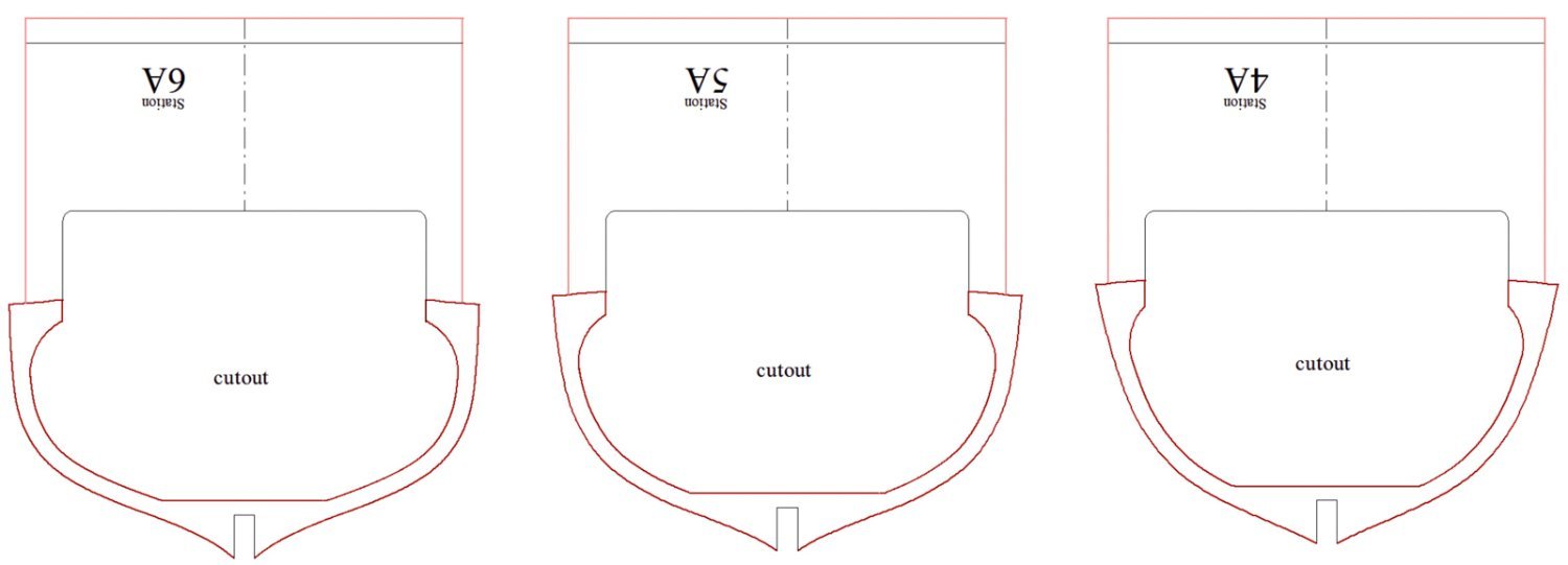
-
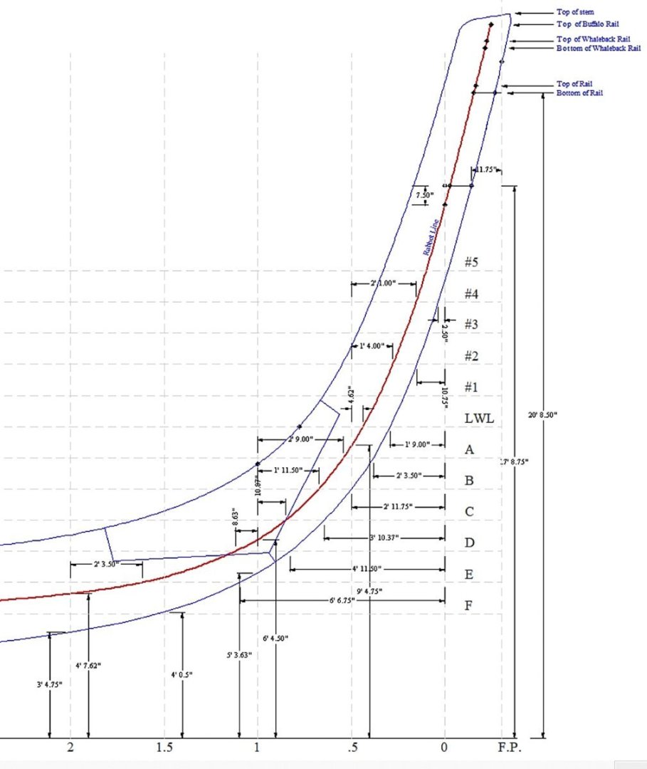
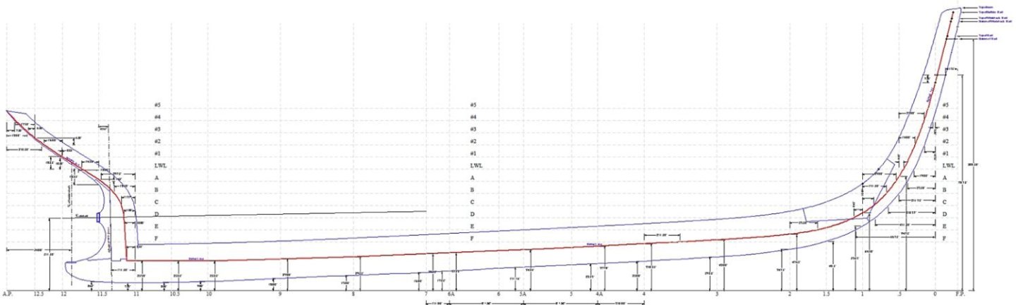
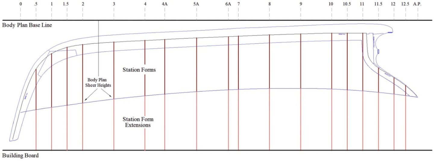
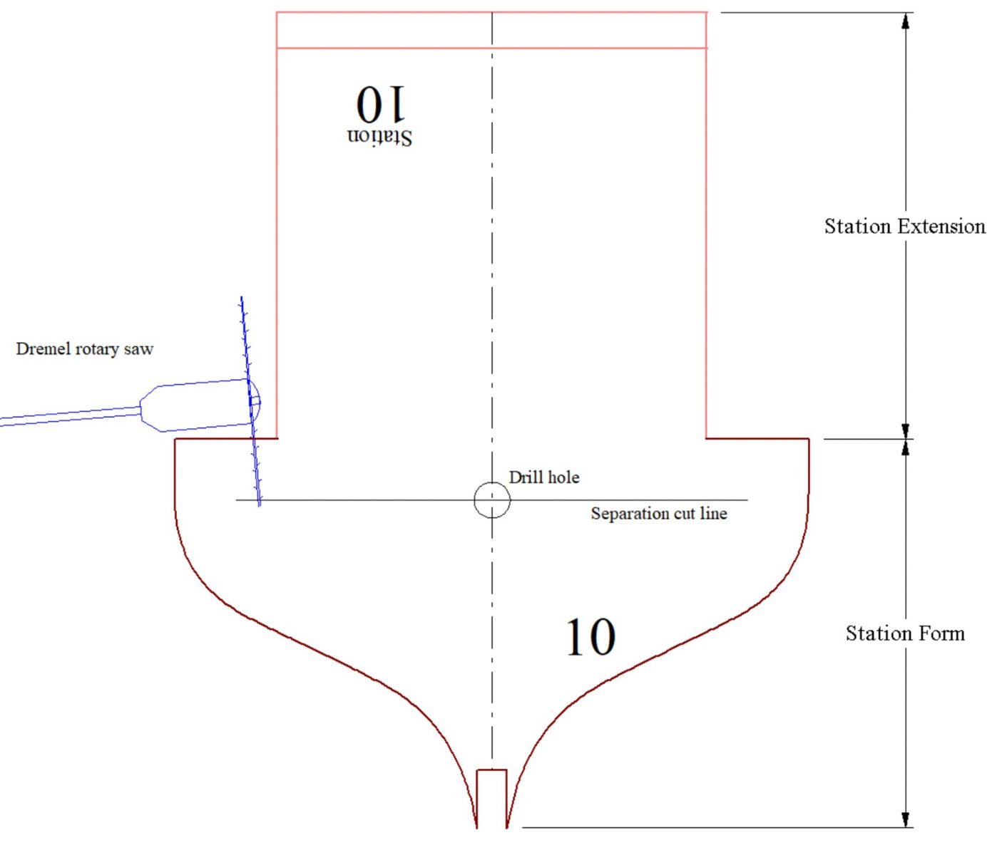
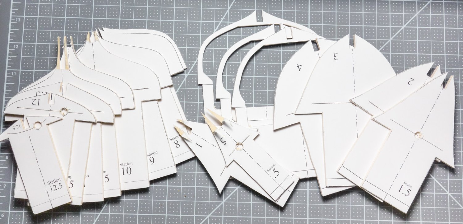
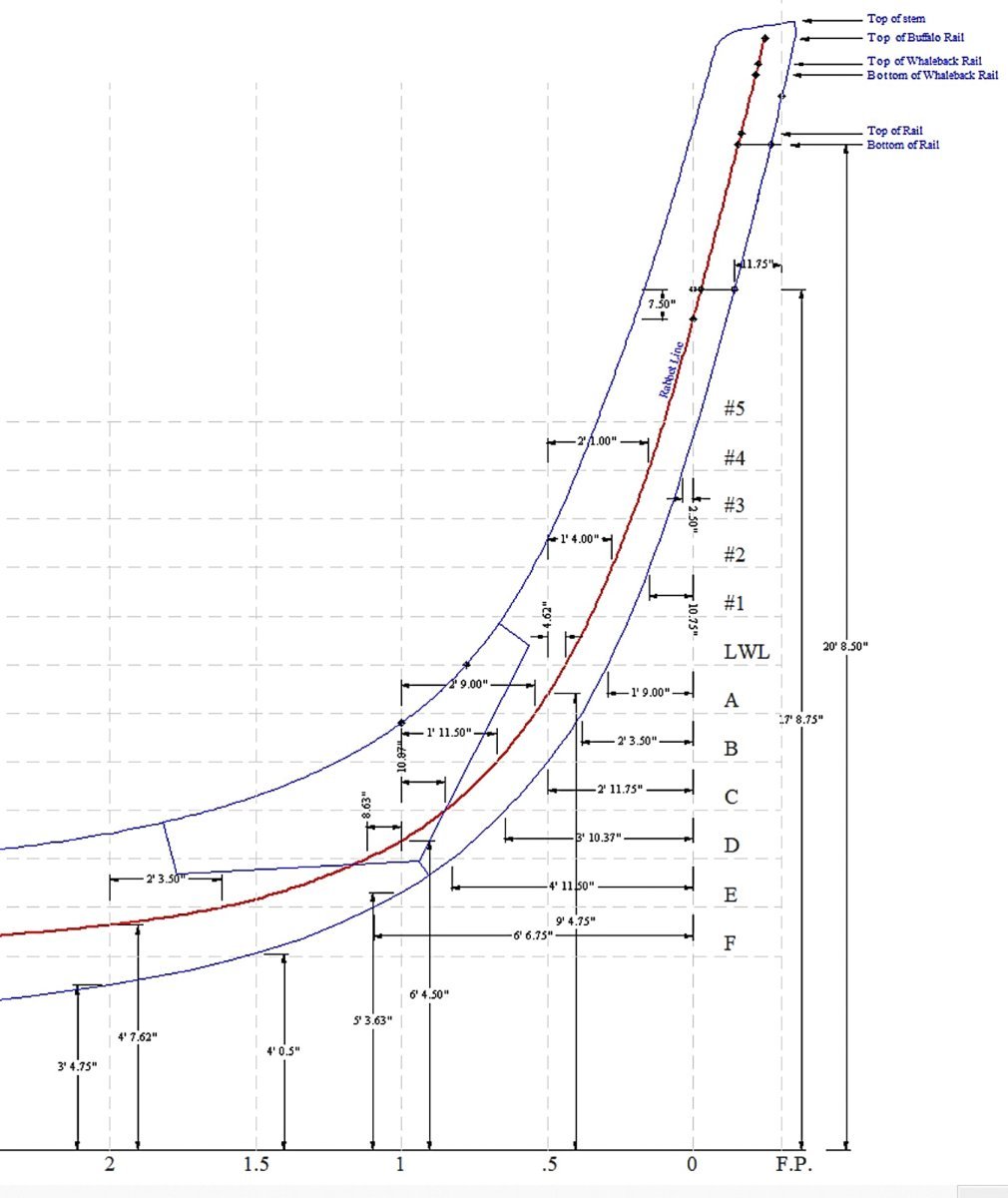
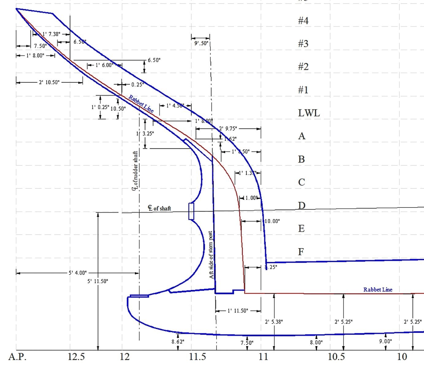
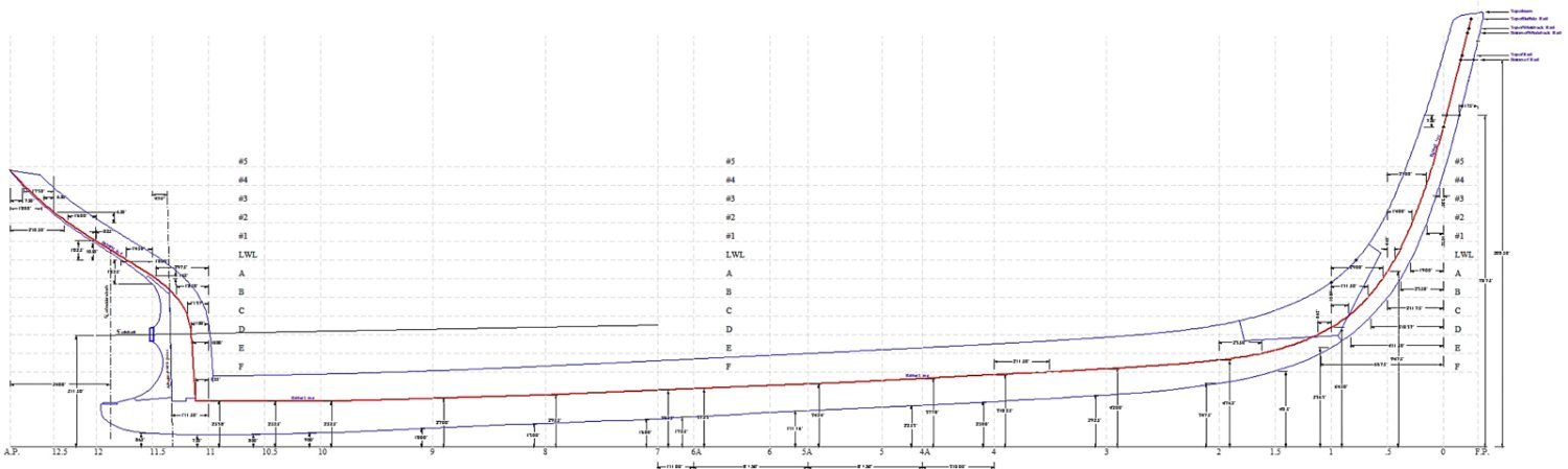
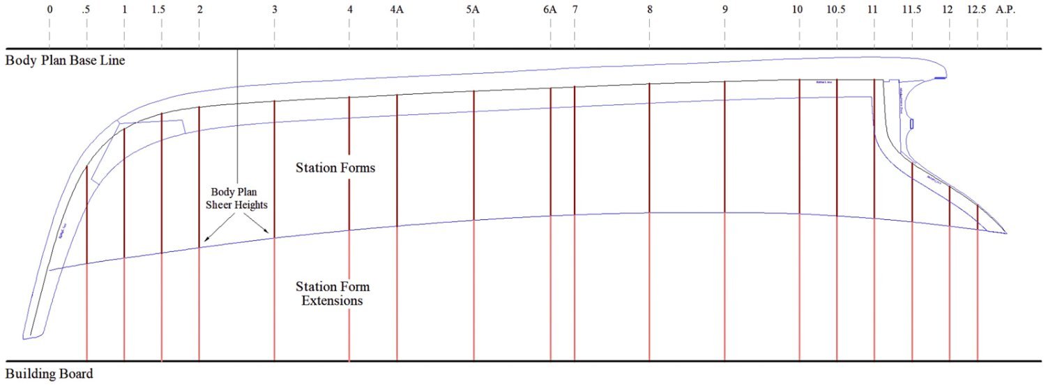
Greetings all and thanks for the kind comments and the "likes". Before moving on to the backbone, the station curves on the body plan need to be completed and developed into station bulkhead form patterns, printed, cut from plywood and finally arranged on a building baseboard. The model will be displayed with the fish hatches open and probably a bunker plate removed to allow a peek into the dimly lit partitioned hold below. The positioning and spacing of the stations as indicated on the original plans are provided only to define the shape of the hull and of course, do not reference any structural element. But because I'm using those stations as bulkhead locations, where they land within the fish hold area is of consequence. As luck would have it, station # 5 intersects the forward hatch and #6 lands on a coaming timber at the aft hatch. So those stations needed to be removed and three new modified stations added in replacement. In the drawing below, the vertical red lines are the removed stations #5 and 6. The blue lines are the replacement stations 4A, 5A and 6A, which as you can see do not interfere with the hatch openings and will provide a landing spot for the hold outer wall planking. Body plan curves for three new stations were generated from the "lines" drawing in the same way station #1.5 was done in my previous post. Stations #5 and 6 were removed from the body plan and 4A, 5A and 6A were added. The added station forms were hollowed out to the width determined by the hull framing at each cross section. Deck beams will eventually strengthen these openings and be installed after the form extensions are cut from the hull and the fish hold is planked and partitioned. The remainder of the station bulkhead forms were then drawn up. Each one has a drill hole mark and separation cut line that will allow the forms to be detached from their extensions once the hull is fully planked. One end of the scroll saw blade will be inserted through the drilled-out hole and used to cut along the separation line. A Dremel rotary saw will be used to make the final separation. I printed the forms on full sheet adhesive labels and affixed them to two 12” x 24” sheets of 1/8” craft plywood taking advantage of the factory cut edge. Scroll sawed, filed and sanded. Attached to the baseboard. Next came the backbone drawings. The original plans show very detailed dimensioning describing the shape of these timbers, so it was mostly just an exercise of re-plotting this data onto a newly created grid. Rather than tracing an imported CAD image, I took this extra step because I already knew the original photocopies were slightly skewed and the import process would have only exaggerated the problem. Here's how the backbone will sit on the station forms shown in profile. Before I physically cut and assemble the backbone, I'll make a cardboard mock-up and test fit it to the forms. It would be beyond irritating to say nothing of embarrassing to spend hours carefully making a backbone that doesn't quite fit because I botched the drawing. I look forward to the end of this preliminary work and to begin actually building the model. Be safe and stay well. Gary