Hubac's Historian
-
Posts
3,308 -
Joined
-
Last visited
Content Type
Profiles
Forums
Gallery
Events
Everything posted by Hubac's Historian
-
 Extremely helpful, I would say, Shipman, and full of interesting knowledge of ships.
- 444 replies
-
- 2
-

-

-
- Cutty Sark
- Revell
- (and 2 more)
-
Thank you EJ! I am honored that you guys continue to follow this build and it is immensely gratifying that you are able to take something away from it. As I told, from the start of this build, the kit I’m building first belonged to my next-door neighbor, who served as an important mentor in my life. Mark Hansen spent countless hours of his personal time, teaching me how to do things. I enjoy posting the build log because I view it as an extension of that goodwill to other builders who might want to play around with this stuff. I do spend an embarrassing amount of time looking at Puget portraits and studying models, but I think that much of this model’s charm has to do with the fact that it has a-symmetries and imperfections and it is full of compromises. It does consistently represent, though, the best that I was capable of at any moment in time. Hopefully, the project won’t plateau, and I’ll keep learning from all of you and your own fantastic builds, and it will all just get better and better. A big thanks to everyone for sticking with this project. It really means a lot to me!
- 2,699 replies
-
- 9
-
-
- heller
- soleil royal
- (and 9 more)
-
Rabbit hole - perfectly expressed. I’m inclined to jump-in, because I know I will eventually build models that really deserve perfect scale rope.
- 444 replies
-
- 1
-
-
- Cutty Sark
- Revell
- (and 2 more)
-
I think you will find, Kevin, that there is definitely a difference with the Syren rope. This past October, I watched Chuck demonstrate his technique at the Joint Clubs mtg in New London. His rope is superb. The best I’ve seen, really. Personally, I’m torn between learning to make rope, myself, where I’m in complete control of the quality, or buying rope. The Amati rope looks very good. For the price, it is - I think - hard to beat. Chuck’s rope would be ideal, but I need a lot of it, and it would be cheaper to make on my own.
- 444 replies
-
- 1
-
-
- Cutty Sark
- Revell
- (and 2 more)
-
Wow, Kevin - that is such a very nice thing to say! Thank you very much!
- 2,699 replies
-
- 8
-
-
- heller
- soleil royal
- (and 9 more)
-
Your decking is really nice, and you have achieved that super-rare, scale-rarity which is realistic grain patterning on individual planks. This really stands out to me.
- 399 replies
-
- 2
-
-
- winchelsea
- Syren Ship Model Company
- (and 1 more)
-
This will probably sound absurd - HOWEVER I personally like to believe that my particular instant obsession with this ship when I was 8 or 9 years old is rooted in the mere possibility of past lives. I like to think that maybe I served on this ship, or at least saw it with my living eyes. It is a nice fantasy 😜, and why my wife refers to her as the other woman. No divorce is not yet imminent; so far, it is a happy poly-amory.
- 208 replies
-
- 7
-

-
-

-
- le soleil royal
- 104 guns
- (and 2 more)
-
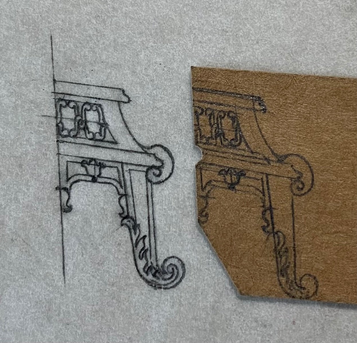
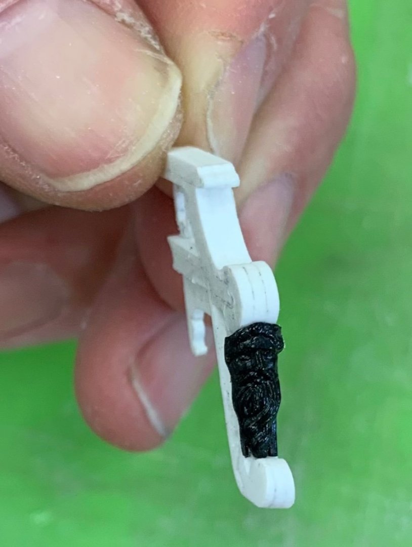
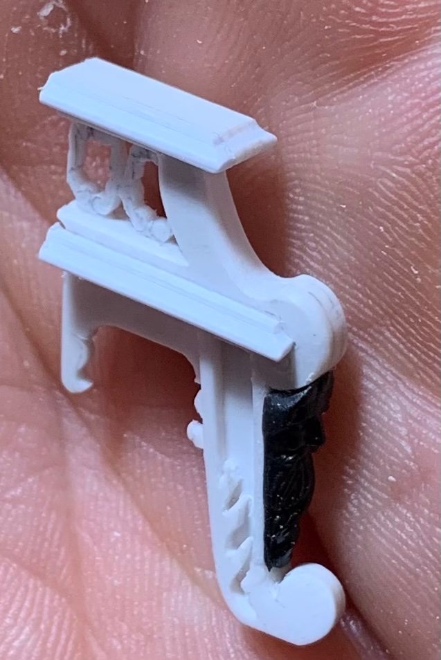
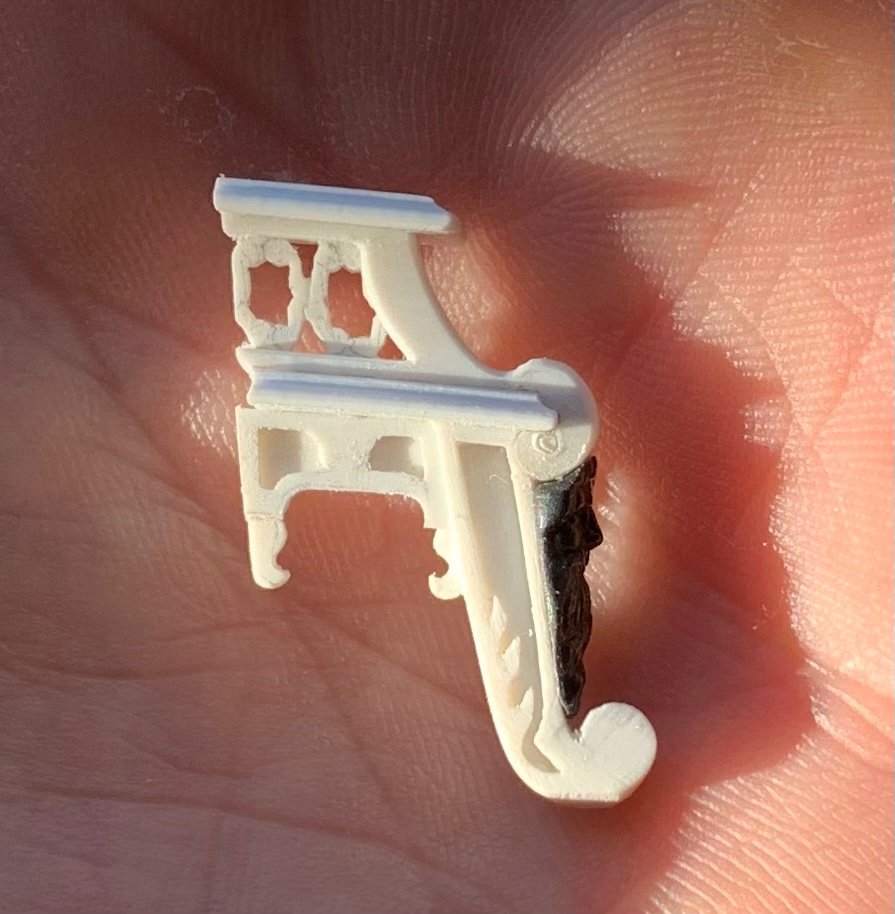
Right you are, Bill! The reason that I will not labor to remake the bracket is illustrated right here: The figures’ vestments will completely obscure the stool that they sit upon. In fact, those pesky clothes will obscure most of the detail I have labored to create on the forward side of the archway bracket. That is perfectly okay with me, though. Vic, I suppose that a real-time video of me “whittling,” as my work friend likes to quip, would be intensely boring; ever watch a termite bore through wood? As a near-sighted person for most of my life, I am adjusting to the mid-life reality of constantly removing my glasses for close work, while simultaneously resisting the pressing need for bi-focals/transition lenses. This is the status of my mid-life crisis. I’ll post a picture of the three main brushes I use, a little later. They are great, but not especially spectacular; all synthetic, and totally in-expensive.

- 2,699 replies
-
- 11
-
-
- heller
- soleil royal
- (and 9 more)
-
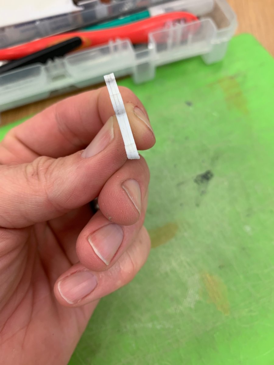
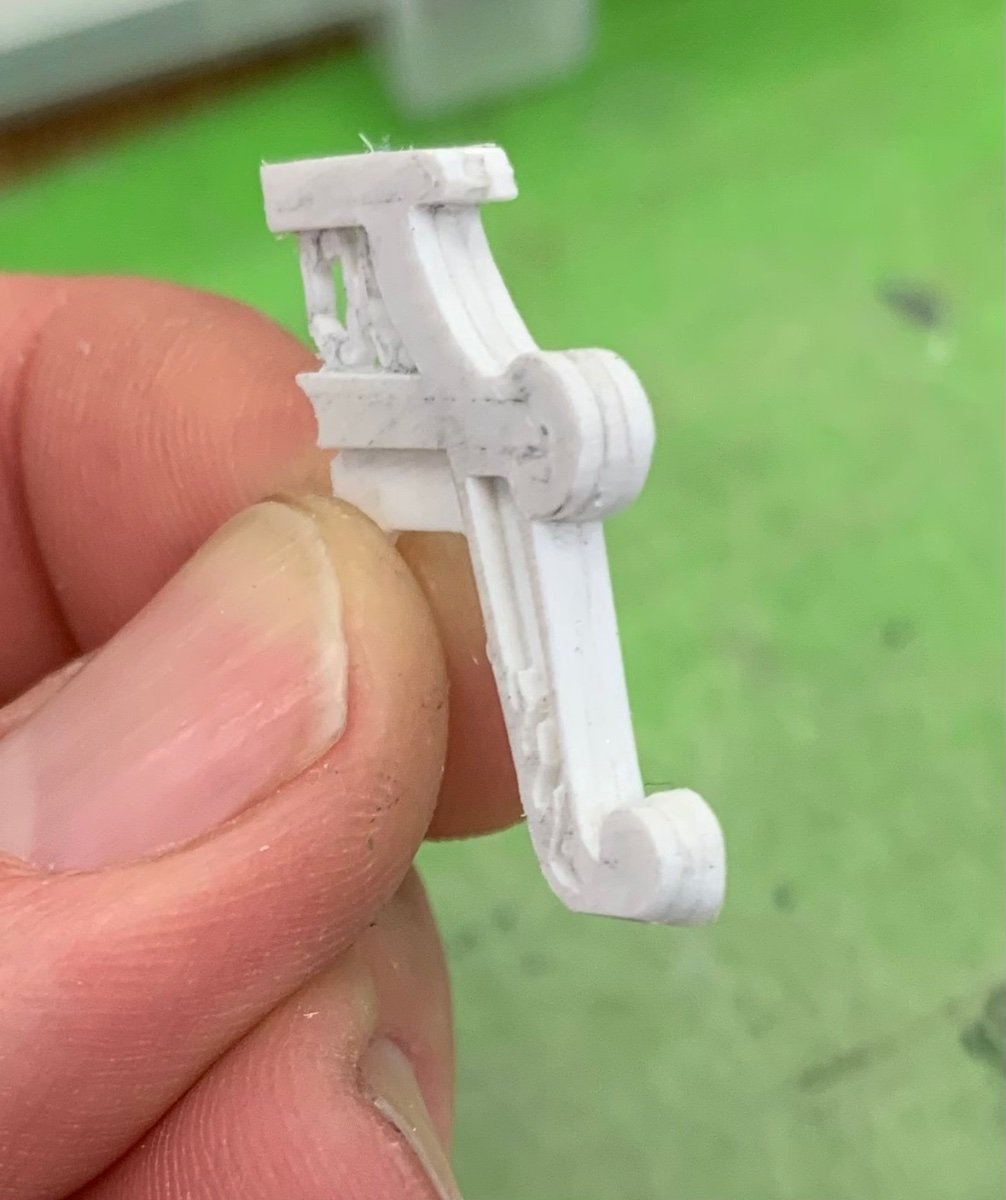
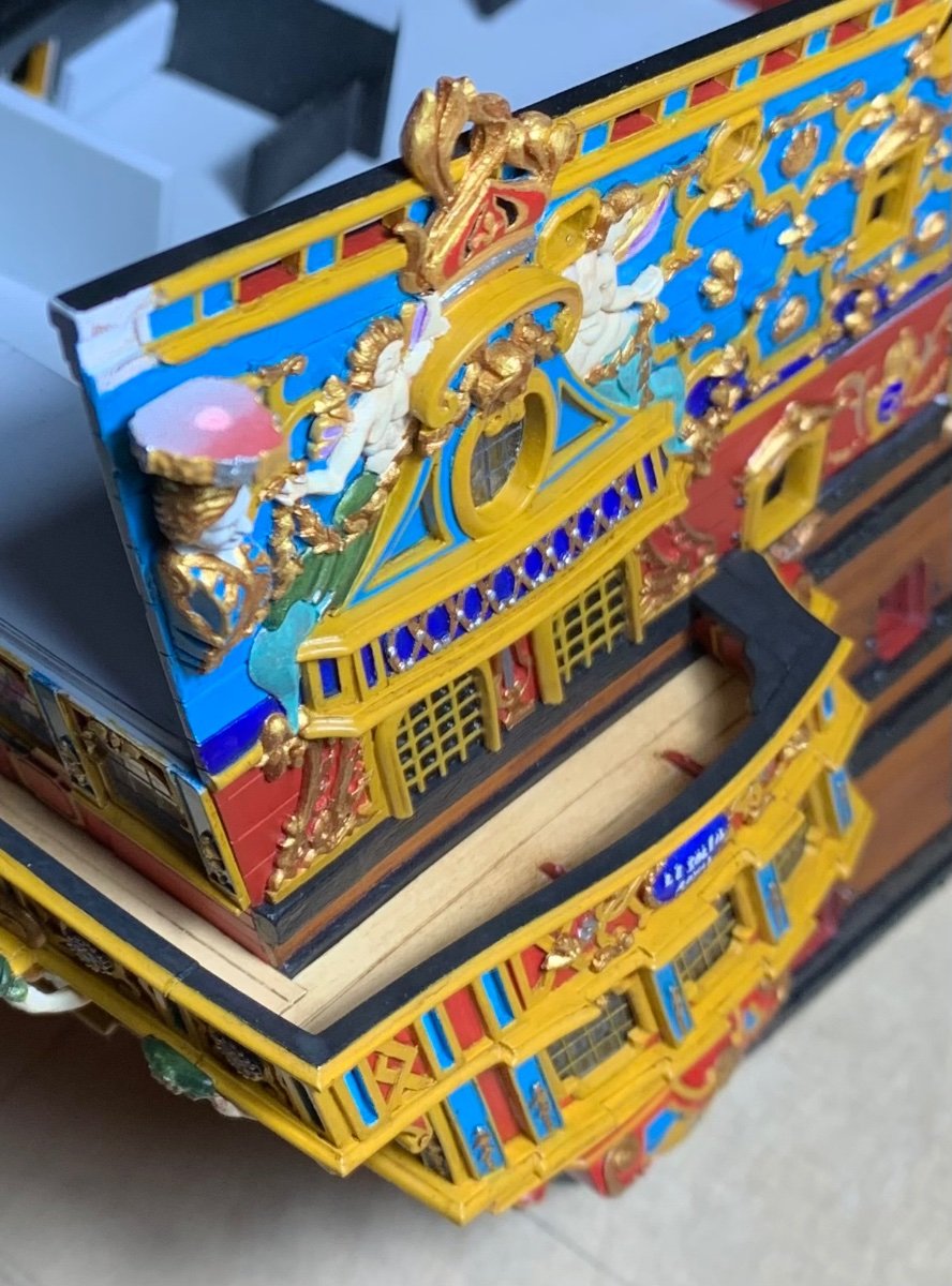
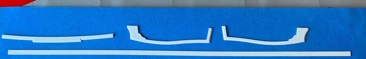
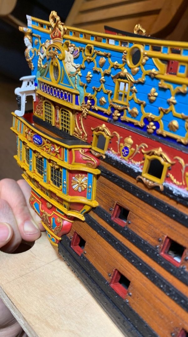
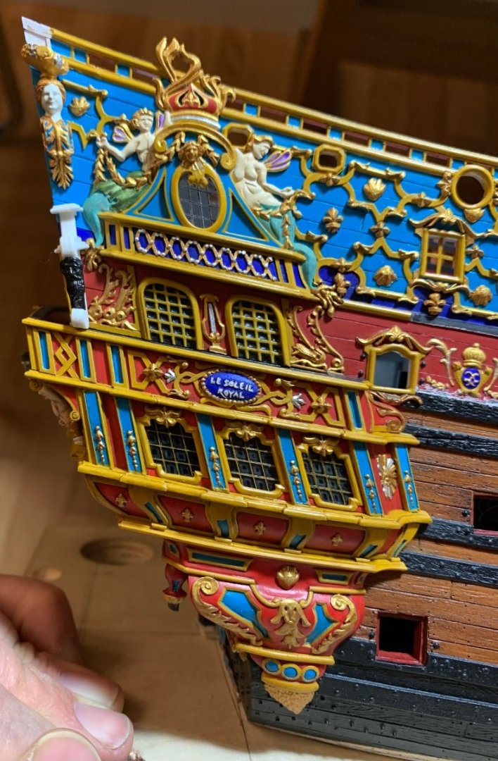
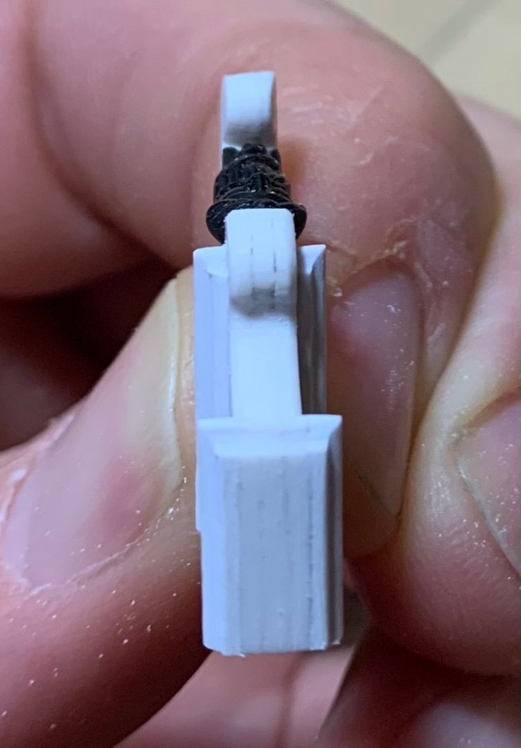
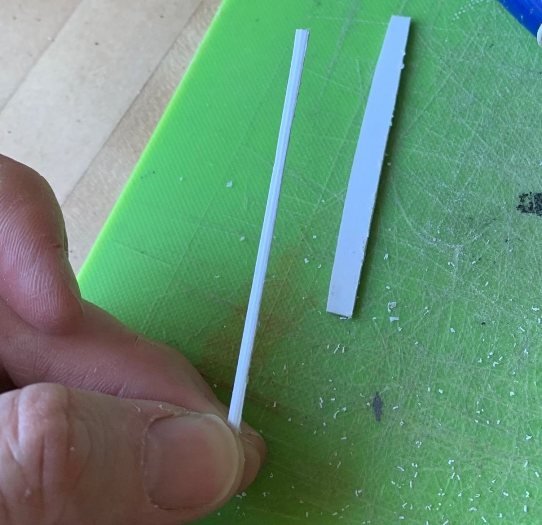
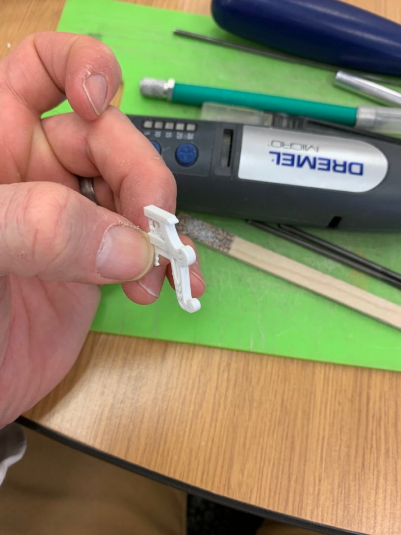
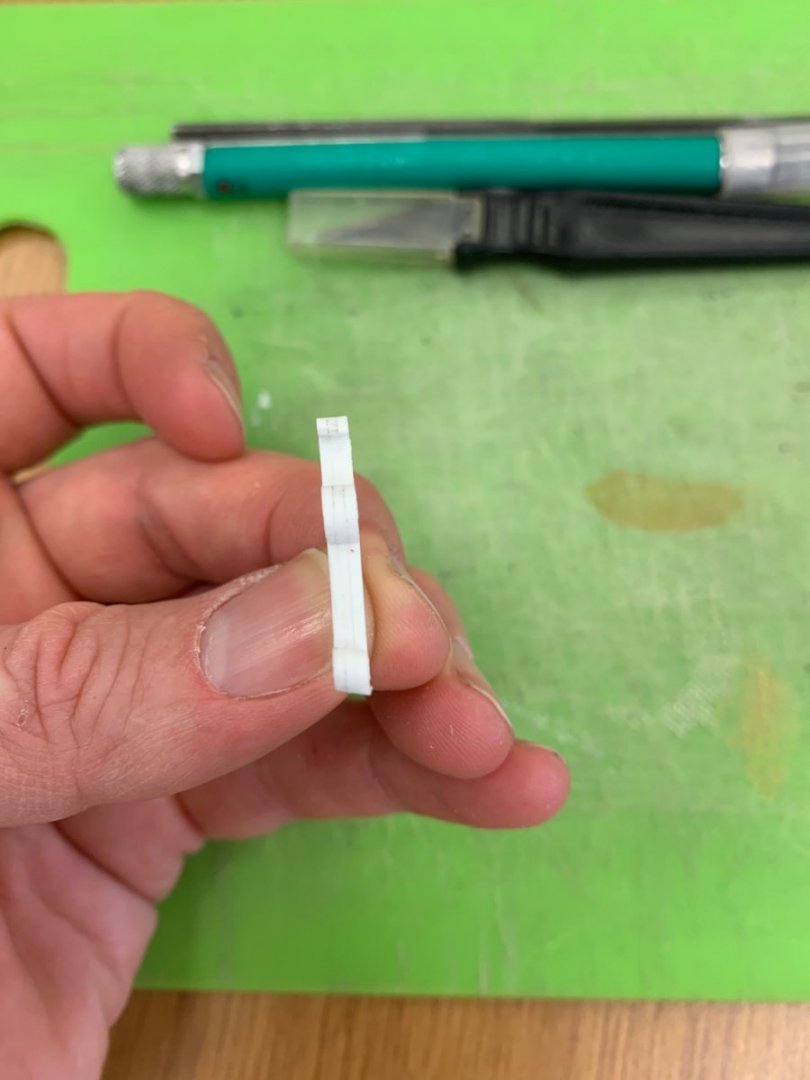
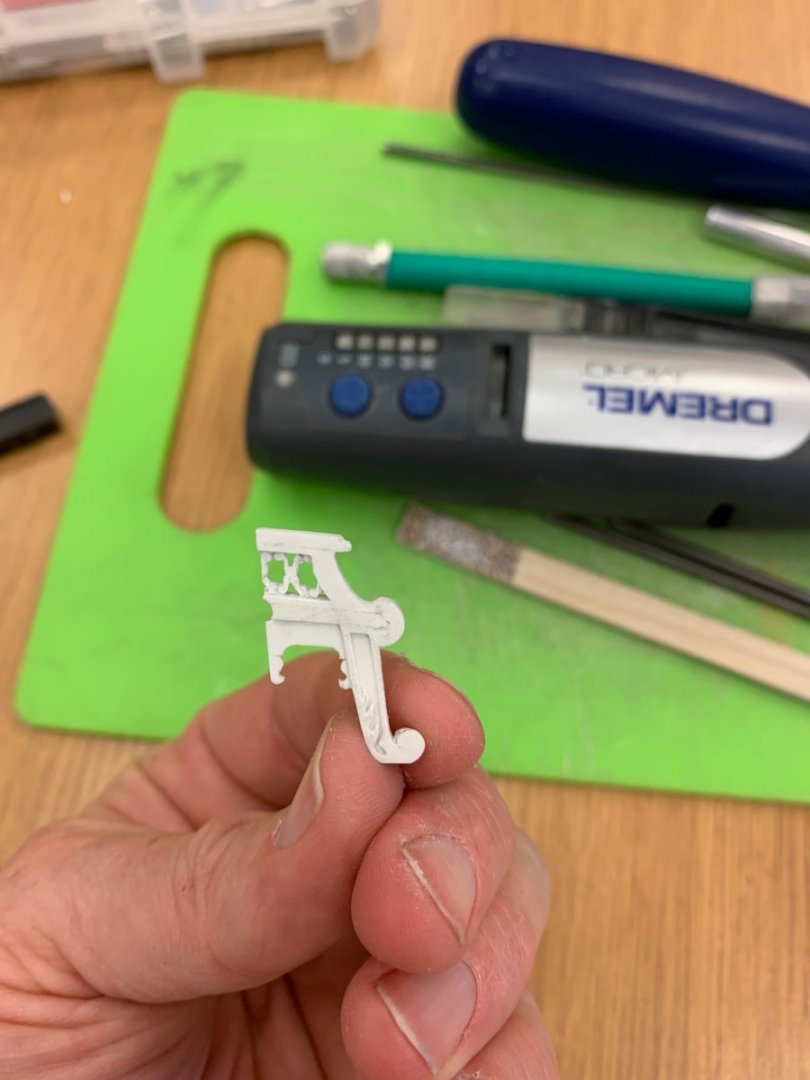
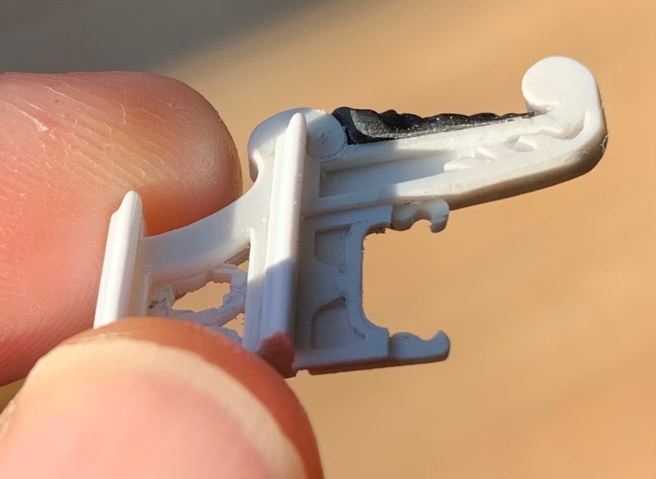
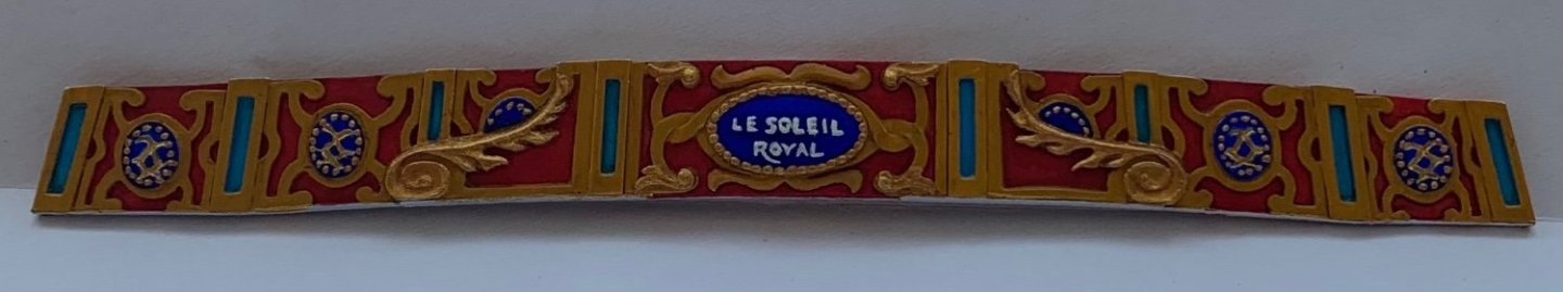
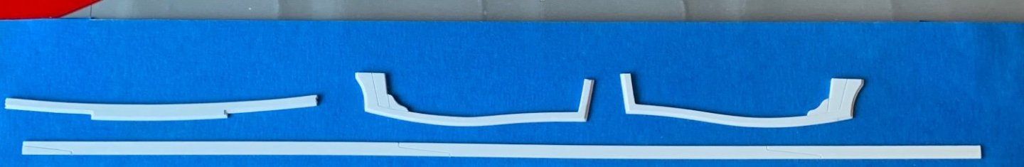
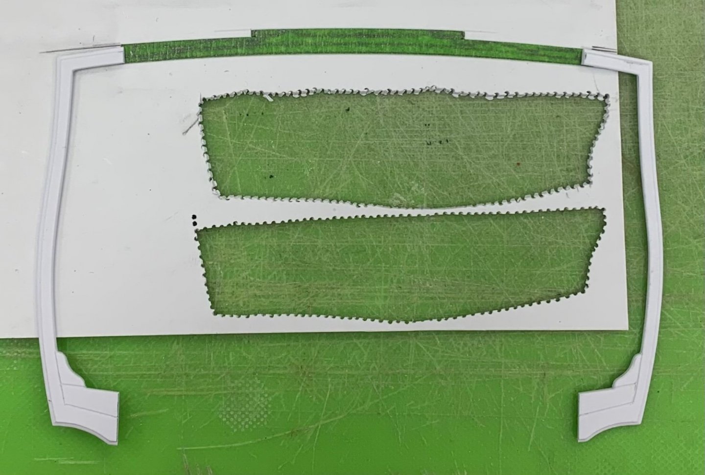
The more I consider your specific point about color saturation, Marc, the more I can appreciate the truth of atmospheric conditions and the way that they impact our perception of color, in real life. Once again, when it comes to diorama ships, Herbert Tomesan comes the closest I’ve seen to getting this right. Your point is well-received and I will do my best to tone it down a bit more. And, yes Vic - one does need to be careful with clearcoats. So, the process of making this first starboard bracket has been highly educational! Anytime I’m making a part like this, I am designing a process to arrive at a level of detail with the least amount of difficulty. For these brackets, one of the primary details that I wished to capture is the pierced filigree of the false canopy. This, much like the trailboard at the head, can only be arrived at through careful piercing and paring, from one side to the other and back again. As always, though, I like cleanly delineated shoulders and panel reliefs, so I thought it would make the most sense to build the bracket up from three primary layers of .028 styrene sheet which, I will show later, gives me just nearly enough part thickness to mount the Four Winds mascaroon. Carving the filigree into a larger supporting lamination is far easier than carving it as an independent insert piece. Above, I’ve already carved the filigree and laminated the aft layer to the center. The edge that joins with the hull is also about a 1/32” oversize, to allow for precise scribing to the hull, a little later. The bottom of the scroll, where it mounts to the bulwark rail, has been left deliberately overlong for final shaping, once the three layers have been laminated together. I was mindful, at this stage, that the back-raking angle of the bracket would necessitate a raking angle for the scrolled foot, as well; were I to shape each lamination to size, before gluing, I would end up with a significant gap, at the forward face of the foot. After lamination and initial scribing to the hull and gallery rail, the foot looks like this: With the bottom angle of the foot established, I could proceed with shaping the scroll and fairing the leg to it’s final form. Here is a montage that shows the evolution of this process: One thing I have found to be true; it is much easier, at times, to “draw” with the tools, than it is with a pencil. I was able, for example, to emphasize an elegant sloping transition into the foot with my files and a sanding stick. Now, when I position the bracket on the model, the negative space of this archway is at a more complementary angle to the adjoining windows than my initial drawing/template. It’s a little hard to read in the following picture, but I have introduced a slight taper to the scroll foot from bottom to top; this is the first step along the detailing path of a scrolled volute. I will show the relief work, in this area, in the next post, after I have attached the acanthus brackets. So, with this much established, I could focus on fitting the mascaroon that I had retrieved from the kit quarter gallery. Given the difficulty of carving convincing faces, it is always worthwhile to see whether one can salvage the kit sculptures. The mascaroons are oversize, but I thought I could make it work. What I am trying to achieve: After much fettling, the mascaroon pares down quite a bit from where it began: Now - the head is unavoidably wider than the bracket, but I will show a little later how simply softening these hard edges makes the sculpture look more like a deliberately rounded relief. I was able to retain just enough of the headdress, so I consider this sculpture experiment a success! Next, I turned my attention to the mouldings which are really just a continuation of the top and bottom rails of the upper gallery bulwark. My idea was to simply profile a piece of scrap 1/16” styrene and then “rip” the moulding off the blank: After truing the back edge, it was a simple task to profile the ends and secure them to the bracket: This approach results in a generous perch for the seated figures: I am currently adding-on the final layer of appliqués: paneled headers, bell flower escutcheons, filigree accents, and acanthus brackets. Here you can see how softening hard edges helps turn a shortcoming into an advantage: Honestly, I don’t think I can do a better job of satisfying the design and artistic challenges of this complicated part. Nevertheless, it did dawn on me that my approach resulted in a fundamental architectural flaw that would never have found its way onto the actual ship. Can anyone spot it? I’ll give you all a little time to mull it over, and then I’ll explain why it won’t matter for this model, and is not worth the monumental effort of remaking the part. I got lucky, this time, but the insight has only deepened my appreciation for these 17th C. shipwrights who managed to knit the whole structure together seamlessly. As always, thank you for your support! More to follow..


- 2,699 replies
-
- 20
-
-

-
- heller
- soleil royal
- (and 9 more)
-
That Citadel ver-de-gris wash is fantastic stuff!
- 208 replies
-
- 4
-
-
- le soleil royal
- 104 guns
- (and 2 more)
-
I will have to look into this - this may be the way for me. I’ve been going back and forth about whether to buy a ropewalk and make scale rope, myself. This feels like one of those things where I’d like to cheat a little and just buy good scale rope - at least for my current project.
-
I’m sorry for the lag, here, Ian. That is a generous offer, but I do have my own Heller Vic blocks - funnily enough, I never focused on their attributes and quality. I’ve held onto the kit since 1995.
-
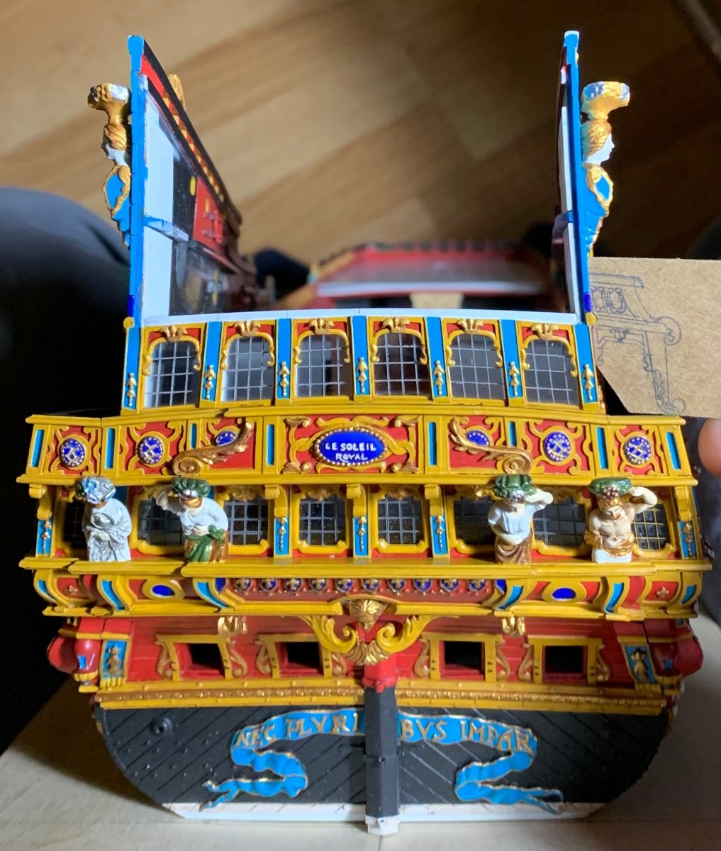
Hello, Marc! Thank you for the kind words! Part of your perception is the photography. I photograph with minimal background light and a bright overhead. This helps pick up the detail. In life, the model is certainly bright, but not nearly so as it seems in the pictures. With each new level of the stern, I am modulating the weather wash (walnut ink), which I will continue to play around with right up until I clear-coat the entire model with a matte finish sealer. This will also help to mute the colors a little. I don’t do much, in the way of set-up for taking pictures. I just try to get a crisp enough image for the log.
- 2,699 replies
-
- 5
-
-
- heller
- soleil royal
- (and 9 more)
-
Thank you GP-Phil! Partly, you are correct - it could angle slightly more inboard, but then it begins to affect my scroll spur (which supports the foot of Africa) in a way that I don’t like. Partly, though, it is the angle of the photo. This all looks a little better, in person.
- 2,699 replies
-
- 7
-
-
- heller
- soleil royal
- (and 9 more)
-
Nice, clean work Eric. Will you go back to New London a week from Saturday?
-
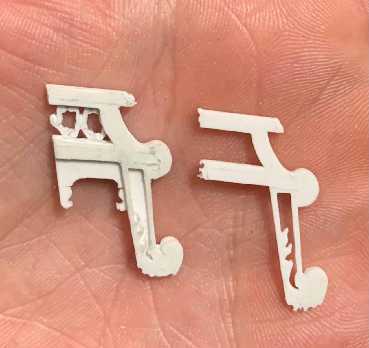
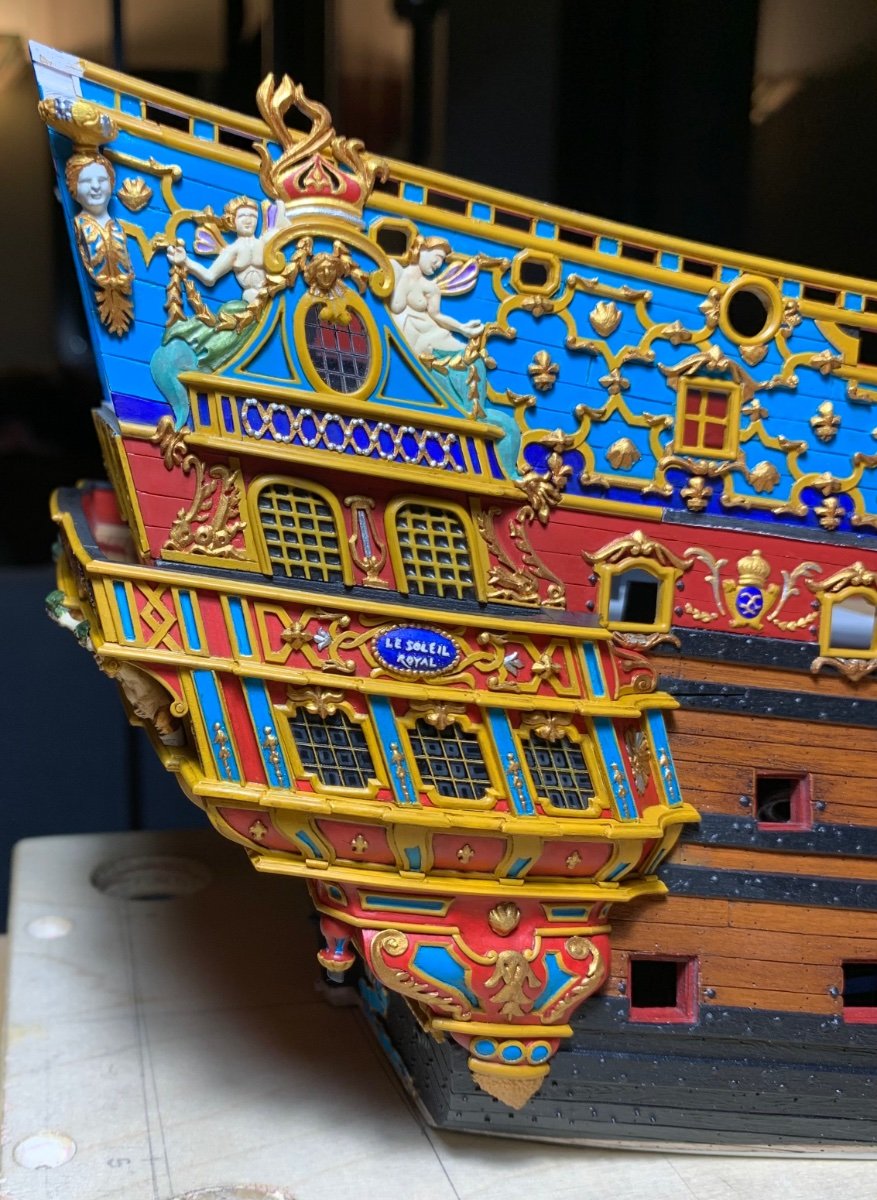
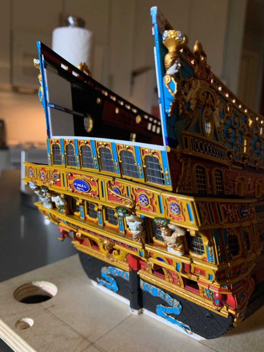
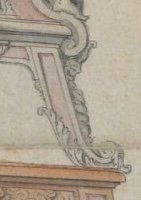
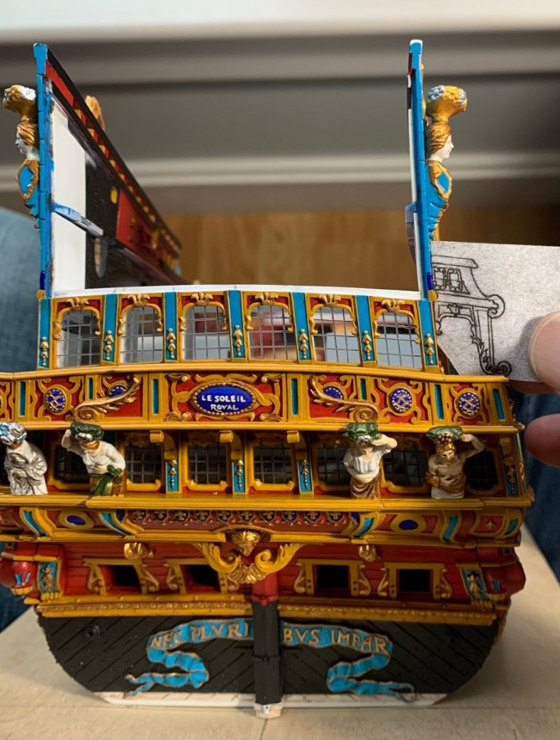
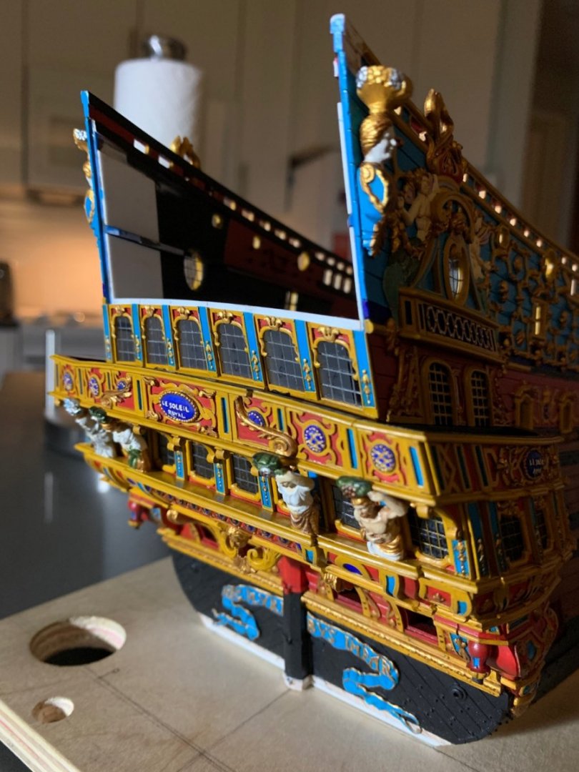
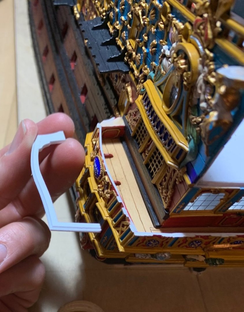
As always, Druxey, you are very welcome. I appreciate your sticking around through this slow, steady climb. It has been suggested to me, by a friend on the other forum, that my pass-through arches might benefit from a slight re-design. His point was that the pedestal support, as it rises from the balcony rail, appears to move slightly away from the ship side: I related that part of the reason for this is that I needed a wide-enough seat to accommodate the figures of Africa and the Americas, so that they wouldn’t seem cramped beneath the quarter-piece supports for the side lanterns. When I reduced the sheer by 1/4”, I lowered these quarter-pieces, as well, so that they would be in-line with the sheer railing, as opposed to above the sheer railing. I even carved away the lower finishing of the quarter pieces and reduced their depth, somewhat, but they still present a challenge to spacing. Nonetheless, the more I studied the problem, I could appreciate that he was right, and I found a path to get ever so marginally closer to what he was suggesting. Now, the differences are slight. I kept the canopy at the same projection as before, but I redrew the support pillar at a slightly steeper angle toward the ship’s side, while increasing its heft. I re-drew all of the scrolls and the acanthus brackets and they are better now. Here is the difference: I will minor-tweak some of these panel reveals, as I make the parts, but this is what the new bracket design looks like against the ship: This is not a dramatic difference, but it is a worthwhile improvement, IMO.


- 2,699 replies
-
- 20
-
-
-
- heller
- soleil royal
- (and 9 more)
-
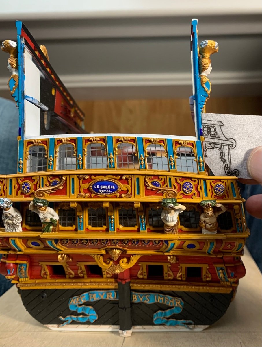
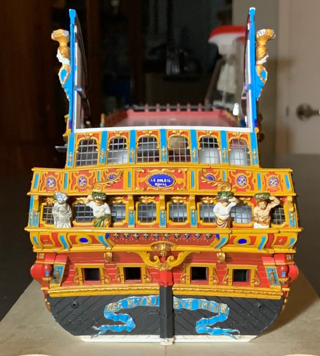
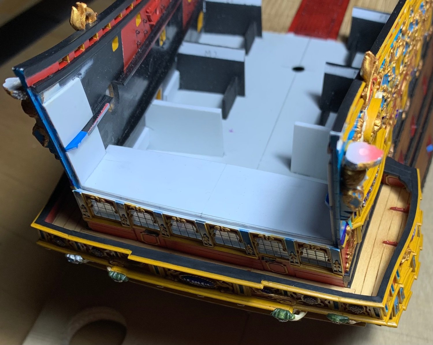
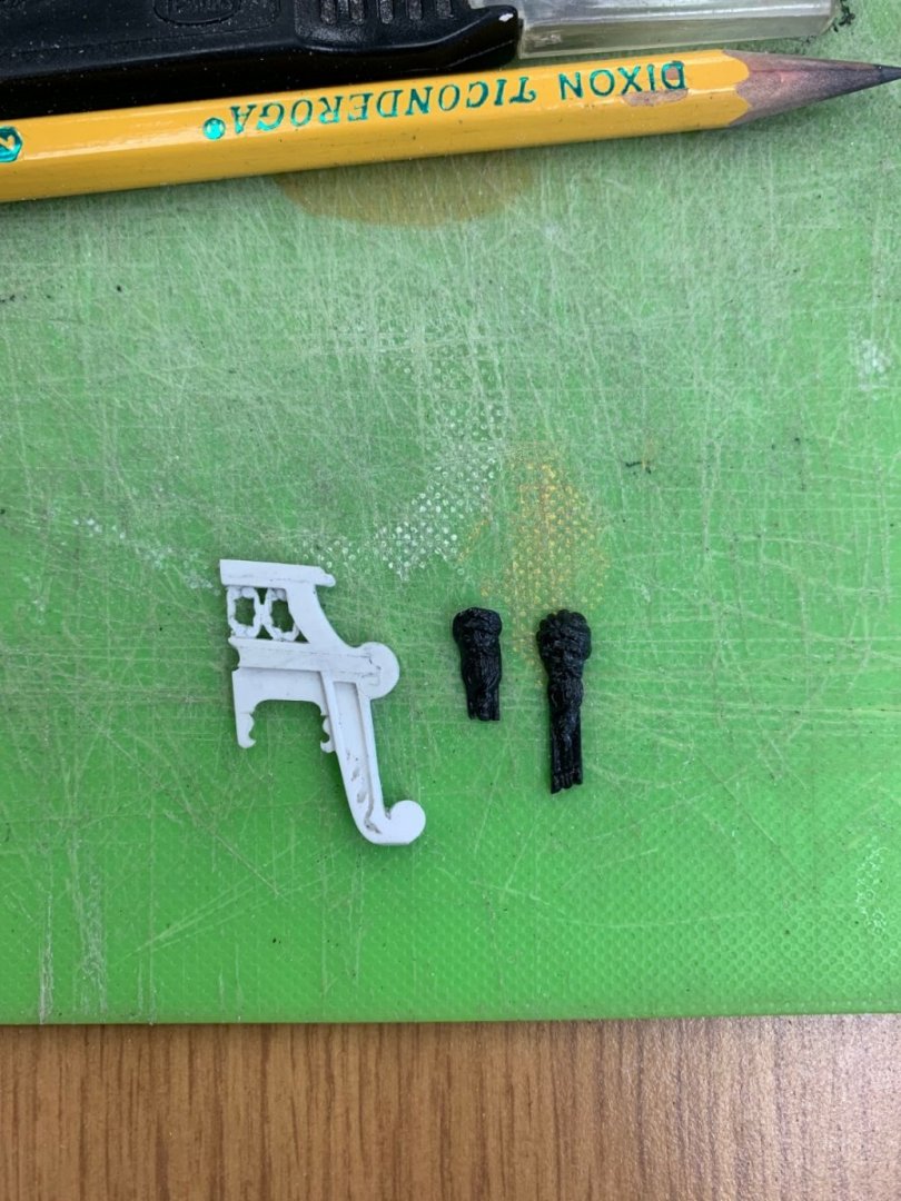
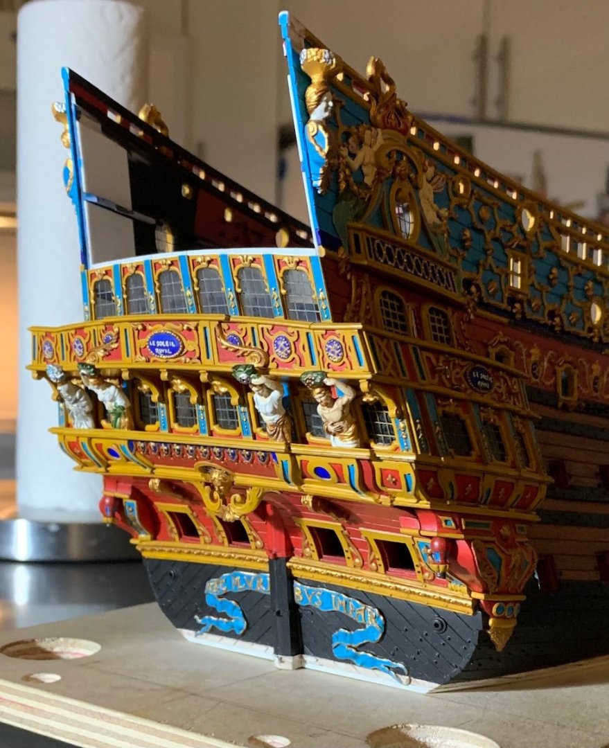
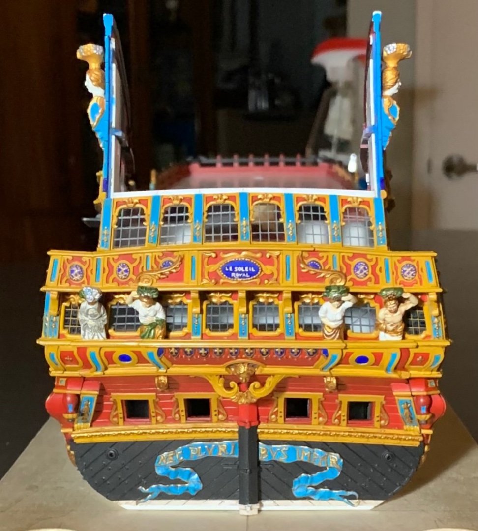
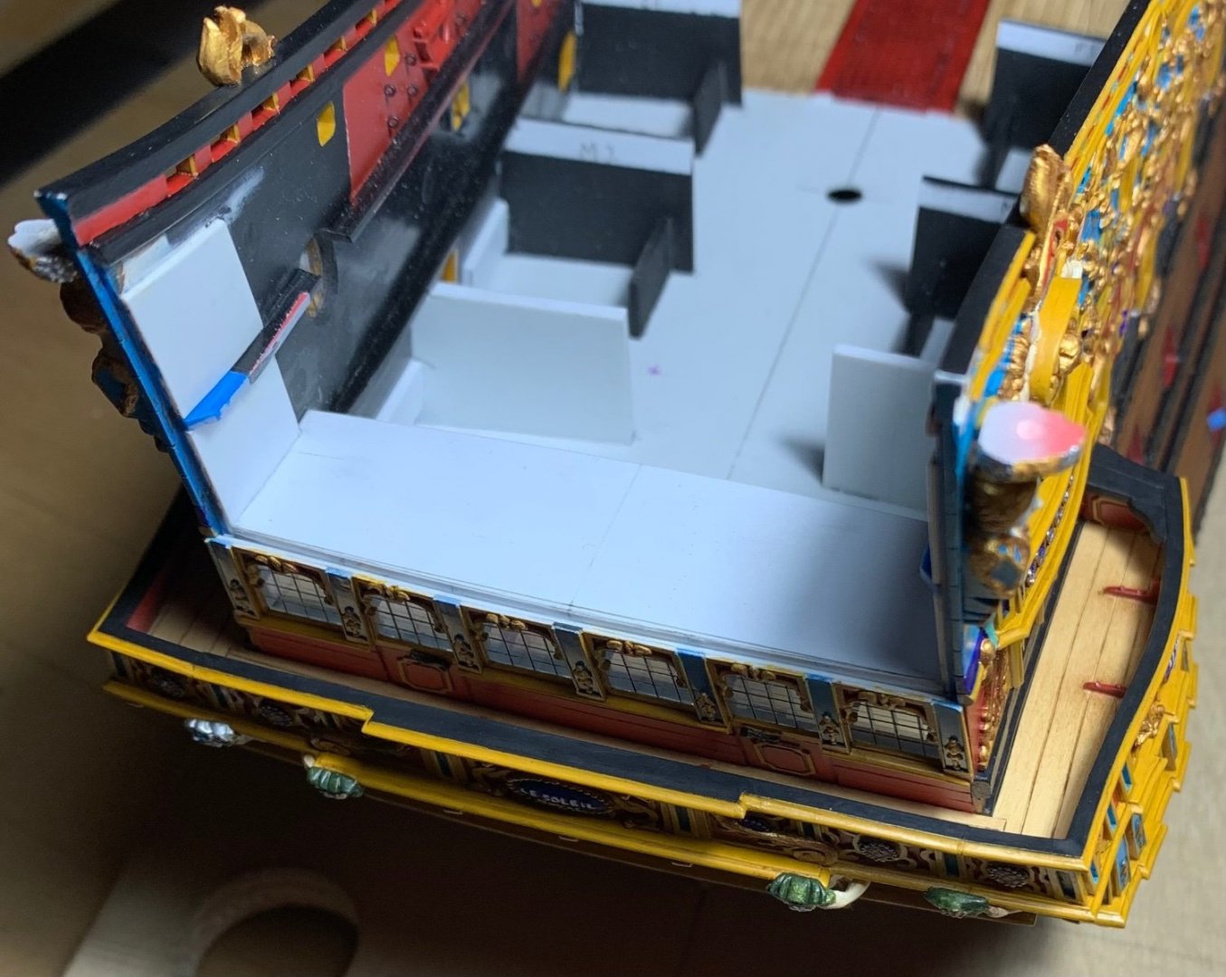
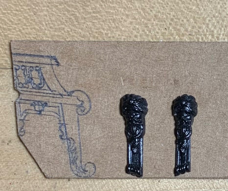
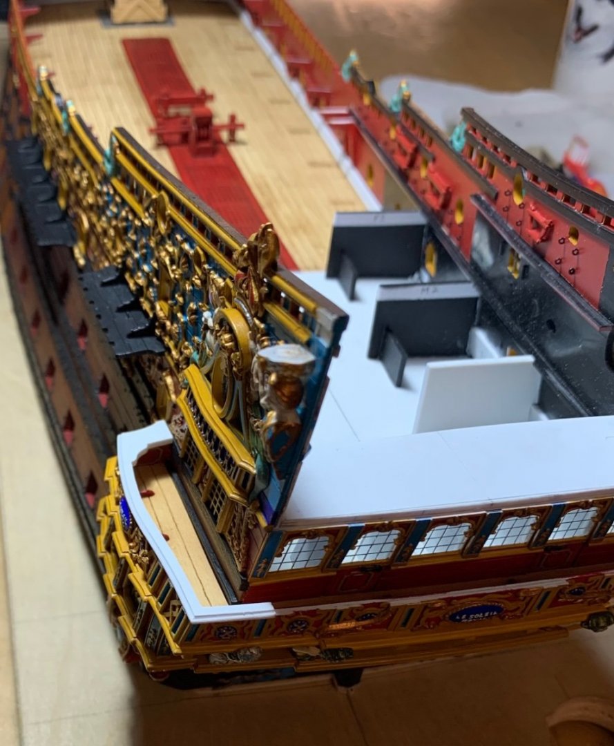
Yesterday was a milestone day as I completed the main deck gallery of stern windows and finally completed the wrapping balcony. Per usual, there was quite a lot of touch-up, but here is where we are after applying the walnut ink wash: Somewhat remarkably, I managed to avoid breaking the aft bulwark supporting knees, the angle of which had to be faired a little to match the corresponding rake of the corner joint. Because the nature of this reverse-engineering project precludes a comprehensive drawing, from the outset, the build is always evolving, in-process. I realized, for example, that increasing the camber on this main-deck tier of windows ultimately necessitated adjusting the camber of the bulwark railing, if those two things were ever to agree with each other. Even though I thought I had set the camber of the windows to match that of the bulwark, it didn’t quite pan out that way, in actuality. Unfortunately, this only became manifestly evident to me AFTER I glued the bulwark in place. For the sake of comparison, here is the relatively flatter camber of the bulwark, prior to alteration: Fortunately, there was enough solid-bond glue surface to enable me to re-shape the bulwark, in place. The bulwark cap-rail, itself, was determined by making graphite rubbings along the top edge with masking tape. This gave me the precise shape, as well as the location and depth of all of the pilasters, so that I could arrive at a reasonable overhang, without making the railing appear too heavy. The forward end of the side cap-rails required some allusion to timbering, considering the need to cover the relatively large-scale expanse of the wooden end-piece beneath it. My big idea was to wrap the side railings over the corner join to the aft bulwark, thus re-enforcing the construction. A few different perspective shots with all of the paint re-touched: So, now the stage is set to make the pass-through archways that also serve as supports for the figures of Africa and the Americas. My adaptation of the Berain design is as close as I can keep it, while still respecting the particular slope of tumblehome on this model. Here, I’ve drawn my proposal directly to a cardboard pattern: These will be fun to make, as I’ve made all other things like this, before; there will be a primary sandwich of three layers of styrene, with two thinner appliqués that make up the acanthus brackets, and applied mouldings that continue the lines of the upper stern balcony. There will be pierced fretwork and applied ornaments and all kinds of fun that add up to about a week of effort to make each bracket. I’ve extracted two of the Four Winds carvings from the stock QGs, that will be fitted to the outboard surfaces of these brackets. I didn’t bother to draw them on the template, but here they are beside said template: They will be reduced, accordingly, to fit between the upper and lower scrolled volutes. As always, thank you for looking in, and for your kind comments and support of the project. More to follow…


- 2,699 replies
-
- 18
-
-
-
- heller
- soleil royal
- (and 9 more)
-
Super stuff, Kevin - it all looks as good as the real thing!
- 444 replies
-
- 1
-
-
- Cutty Sark
- Revell
- (and 2 more)
-
Gary - it is fascinating to watch your and Siggi’s build unfold; you are brothers from a different set of “mother” plans. I look on with the highest respect and admiration.
-
Ian, as I consider your thoughts on modifying Heller’s SR blocks, I am already regretting throwing mine away. I am not un-familiar with them. The biggest issue was not having a stropping groove. Still, though - really good scale blocks are expensive.