

Vladimir_Wairoa
-
Posts
1,566 -
Joined
-
Last visited
Content Type
Profiles
Forums
Gallery
Events
Posts posted by Vladimir_Wairoa
-
-
-
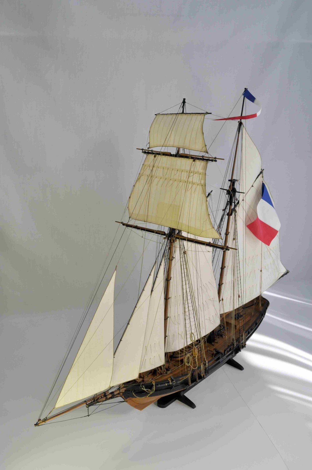
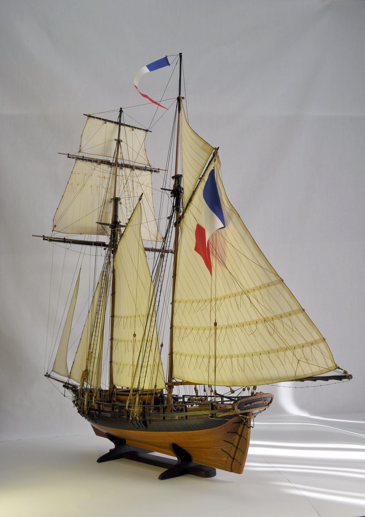
On 8/9/2019 at 11:33 PM, GrandpaPhil said:
The Prince de Neufchatel is done.
It’s my first ever scratch build.
I learned a lot from this build.
I thoroughly enjoyed it.
It’s not perfect, but it’s not bad for a first try.
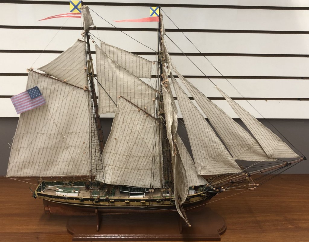
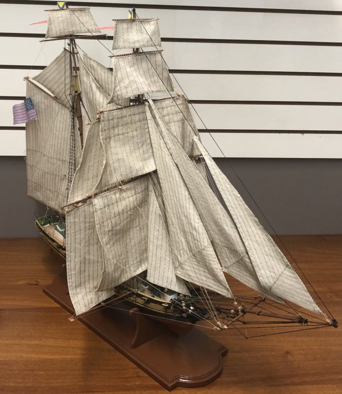
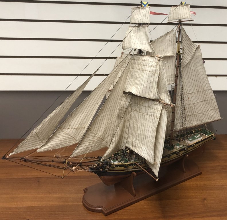
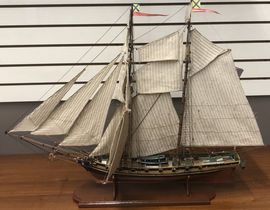
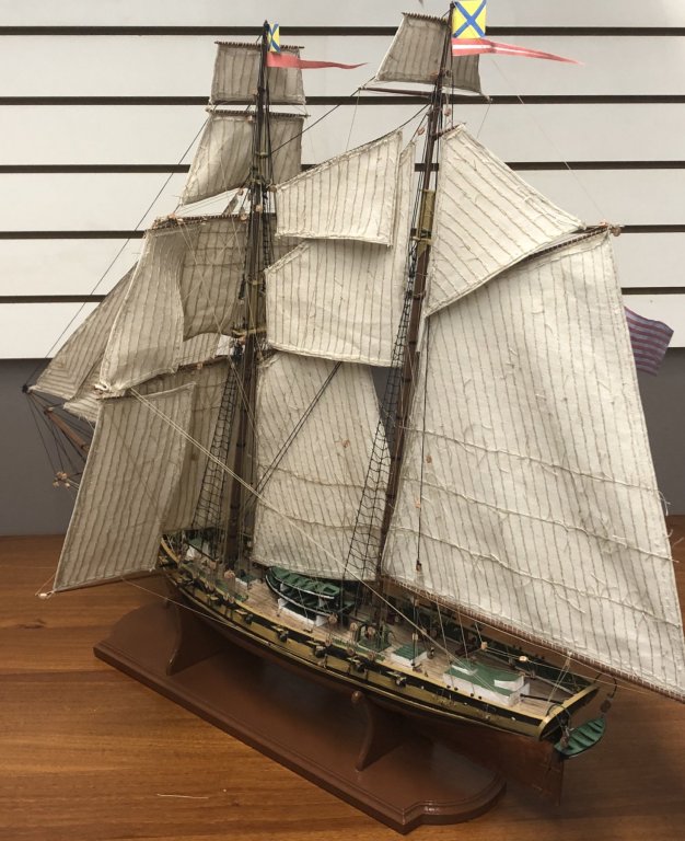
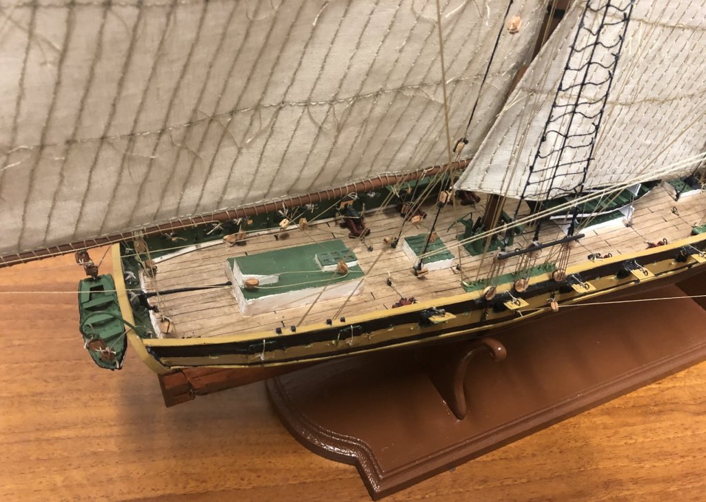
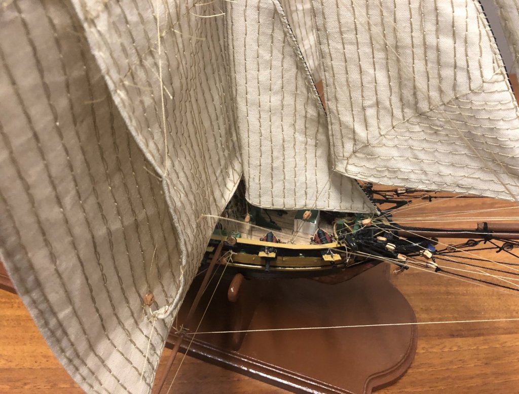


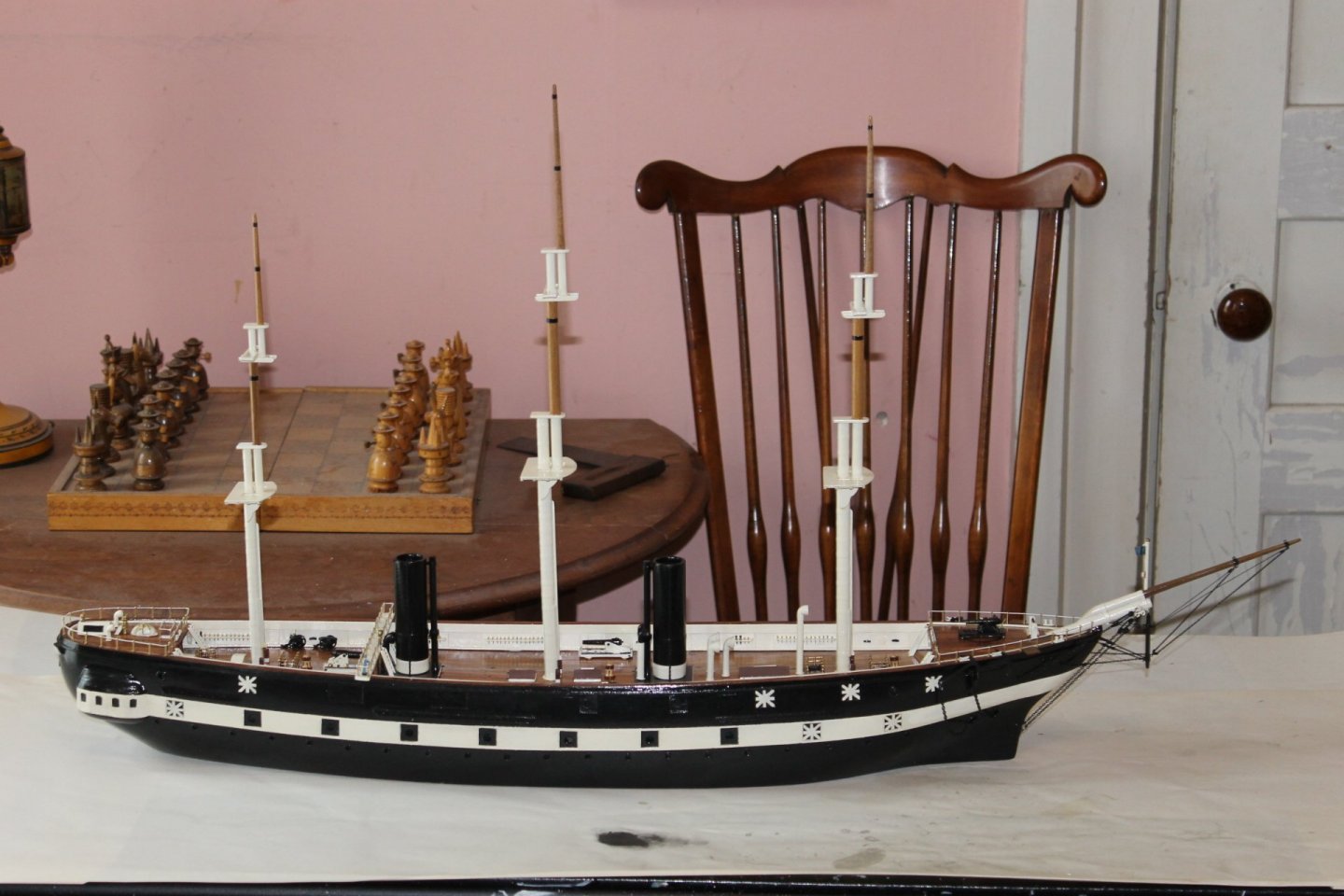
Beutiful GrandpaPhil. i can imgine her fly under such enormous sails. thak youvlad
- GrandpaPhil and mtaylor
-
 2
2
-
On 12/15/2019 at 6:41 PM, Gregor said:
The interior, part two:


To be continued soon...
oh my. thank you . so sweet .
-
On 8/16/2020 at 12:49 AM, Edwardkenway said:
Hi again, thanks to everyone who has looked in and also for the likes.
Planking on the port side slowly proceeds, as I put planks on from the keel and the main wale, I kept adjusting the marking out for the plank lines and it seemed to help.

Another day and it's done, I'm much happier with this side than the starboard,
stern planking is also done, but I think that I will put a moulding across the bottom of the counter.
just need to give both side a good sanding, paint the main wale and a coat of matt varnish or oil.
I am happy I've got the planking done, I'm hoping that when I do finally start to planking Winnie that the AYC will edge bend better than the walnut I used here. The cedar I used on Triton definitely in my opinion took bending alot easier!!
Til next time
Cheers 😃😉👍
i clap hands as well very very nice. hat off. .Vlad. british cutters are so special.
- FrankWouts and Edwardkenway
-
2
-
On 6/6/2020 at 12:20 AM, Keith Black said:
Thank you Roger, Tony, and Gary for the comments and kind words and thank you to all for the likes.
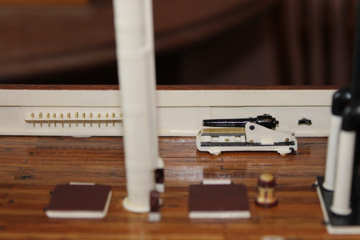
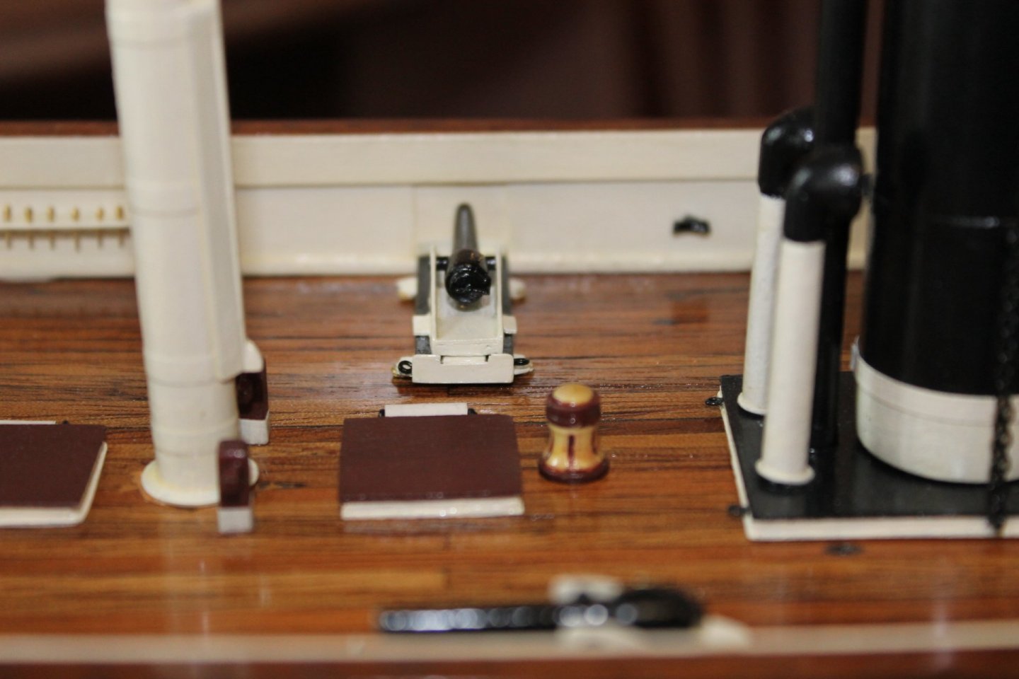
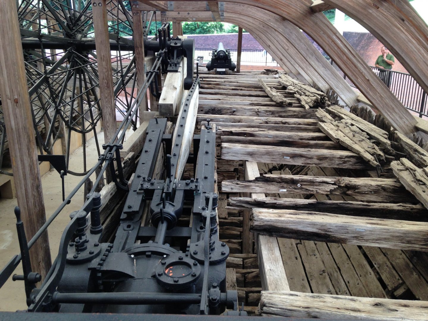
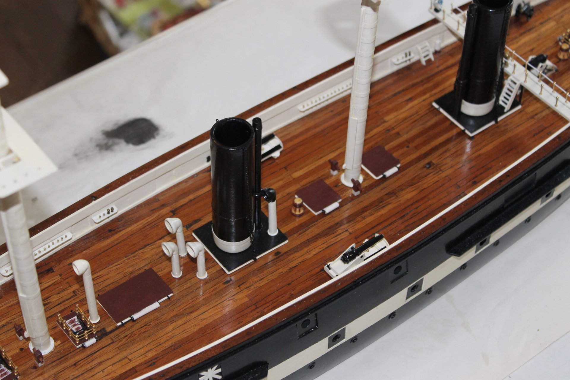
The two 100 LB Parrott breech loading rifles are done with the exception of the circular deck tracks. I'll be making those next.
100 LB Parrott breech loading rifle statistics: Bore, 6.4 inches. Barrel length, 138 inches (11.5 FT.) Barrel weight, 10,266 LB. Shell, 80 or 100 LB. Charge weight, 10 LB. Maximum range, 7,810 yards at 30 degrees (80 LB). Flight time, 32 seconds. Crew size, 17. This from Wikipedia.


Very nice clean workKeith, I like the floor particularly among other things. like real. what an interesting ship.
- wefalck, druxey, Keith Black and 3 others
-
6
-
On 8/24/2020 at 8:31 PM, mbp521 said:
Hello again everyone,
So it has been a very unproductive productive week or so.
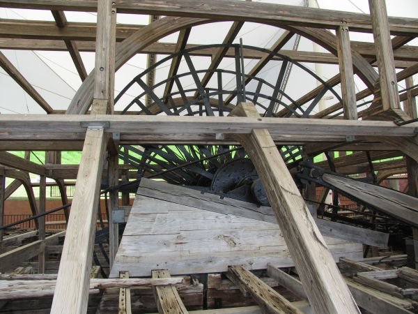
I started working on the engines last week and got them about halfway built when I started to realize that they just weren't looking the way that I wanted them to. Unfortunately there are no real good detailed drawings of them (the HSR drawings are somewhat useful but are still a little lacking in details), so I am having to rely on photos of the actual Cairo and other builds to get an idea of the shape and reasonable size of them.
Working off the photos is tough given that everything is painted black and doesn't show a lot of depth.
So I gave it a shot to see what my first version would look like.
I started with the bottom support rails. The width was pretty easy to figure out since the HSR Gun Deck Plan drawings have them in place and since I have the plans scaled to 1:48 I could get this part close.
I then turned down and carved the connecting yokes.
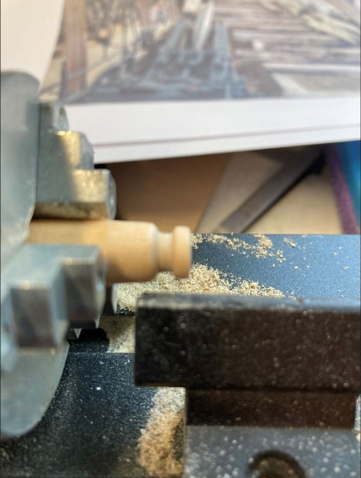
Then using 3 different size dowels I made up the steam drums and piston rods and laid out the assembly.
It was here that I started to think that they just weren't looking correctly proportioned. So I decided to work on other features and figured I'll circle back to these when I can get a better understanding of the size proportions between the assemblies.
So I decided to start work on the support pillars for the engines and paddle wheel. These were a little easier to figure out. The hardest part of this was getting the height position of the paddle wheel and the correct angle of the timbers.
These are the ones from the actual boat. Although they are not original, they gave me a general idea of how they were constructed.
These are my versions.

These are all just dry fit for now. I am waiting on another order of scale lumber to complete some of the interior walls. Once I have those in place can get everything glued down.
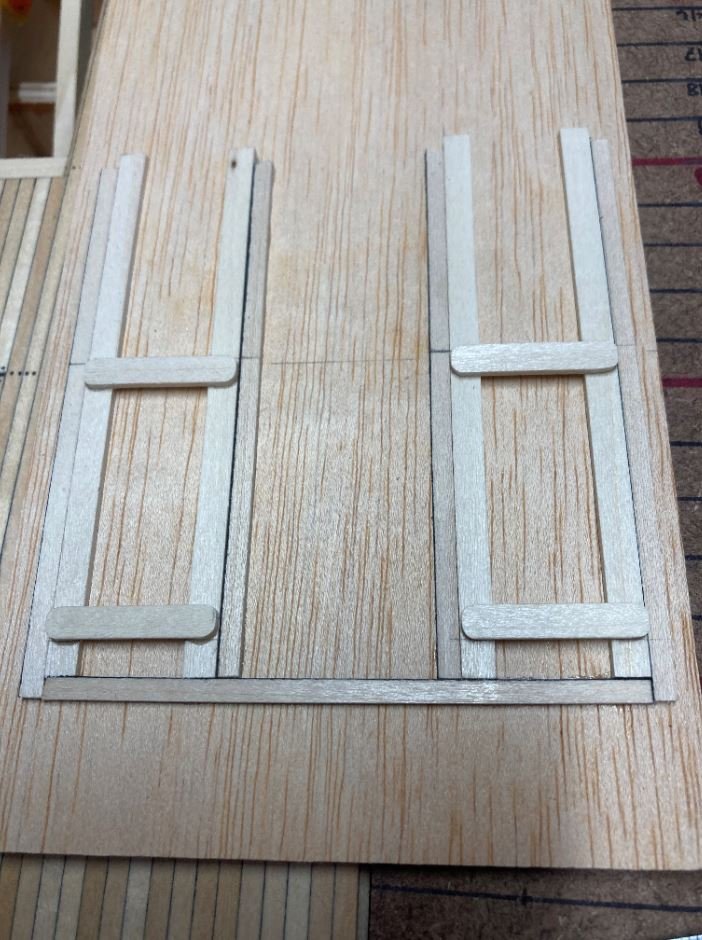
Next, to stall for time while still pondering my engine dilemma, I decided to get the toe boards in place for the crew quarters.
Starboard quarters.
Port quarters.
Lastly I finished installing all of the hatch covers and cut out the rough version of the Pittman arm wooden inserts. These will be used a rough draft for now until I can get the engine situation straightened out. I just wanted to see what it was going to take to get these carved out.
Pittman arms.

And how she sits now (pardon my foot photo-bombing the picture). I removed the boilers and set them aside so they wouldn't get dinged up while working on the other features. I still need to get the boiler hold painted with a whitewash and touch up the coal, but I'll get there.

Doesn't look like very much right now, but soon I will start going vertical and it will then begin to look a little more like a gunboat instead of a barge.
That's all for now. Thanks for taking the time to visit.
-Brian
Very nice work Brian. Vlad
- dcicero, Keith Black, mtaylor and 2 others
-
5
-
14 hours ago, mbp521 said:
Vlad,
Magnificent job on the Captains gig. I have four cutters to build from my Cairo. I can only hope they come out half as nice as this one did.
Sorry to see this project coming to an end. I’ll have to switch over and follow you progress on your Glory of the Seas build.
-Brian
Thank you, cmon Brian, if I can do it, everyone must! :)loooking fwd to see yours!
-
Thank you Guys! well i still stay commited to finish her with propriate detailing like rudder, lifeboats metal fittings and rudder hinges, poop deck rail, and display stand. working on it by evenings more to come soon. some like catheads openings metal sheet already done, some small parts still pops up...stay tuned.
") V.
V.
-
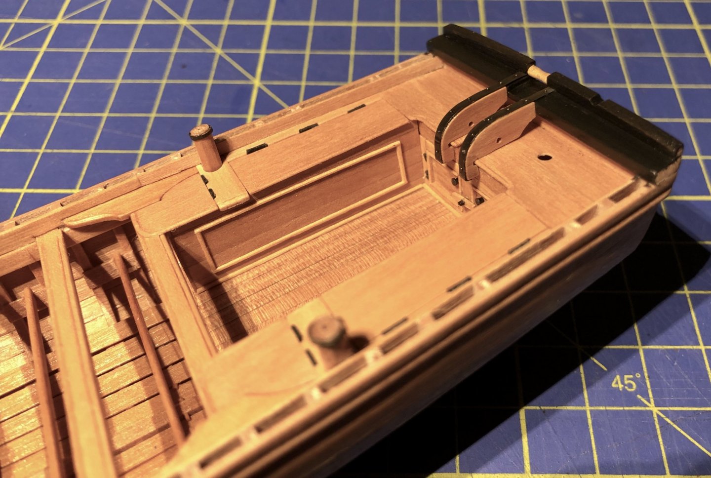
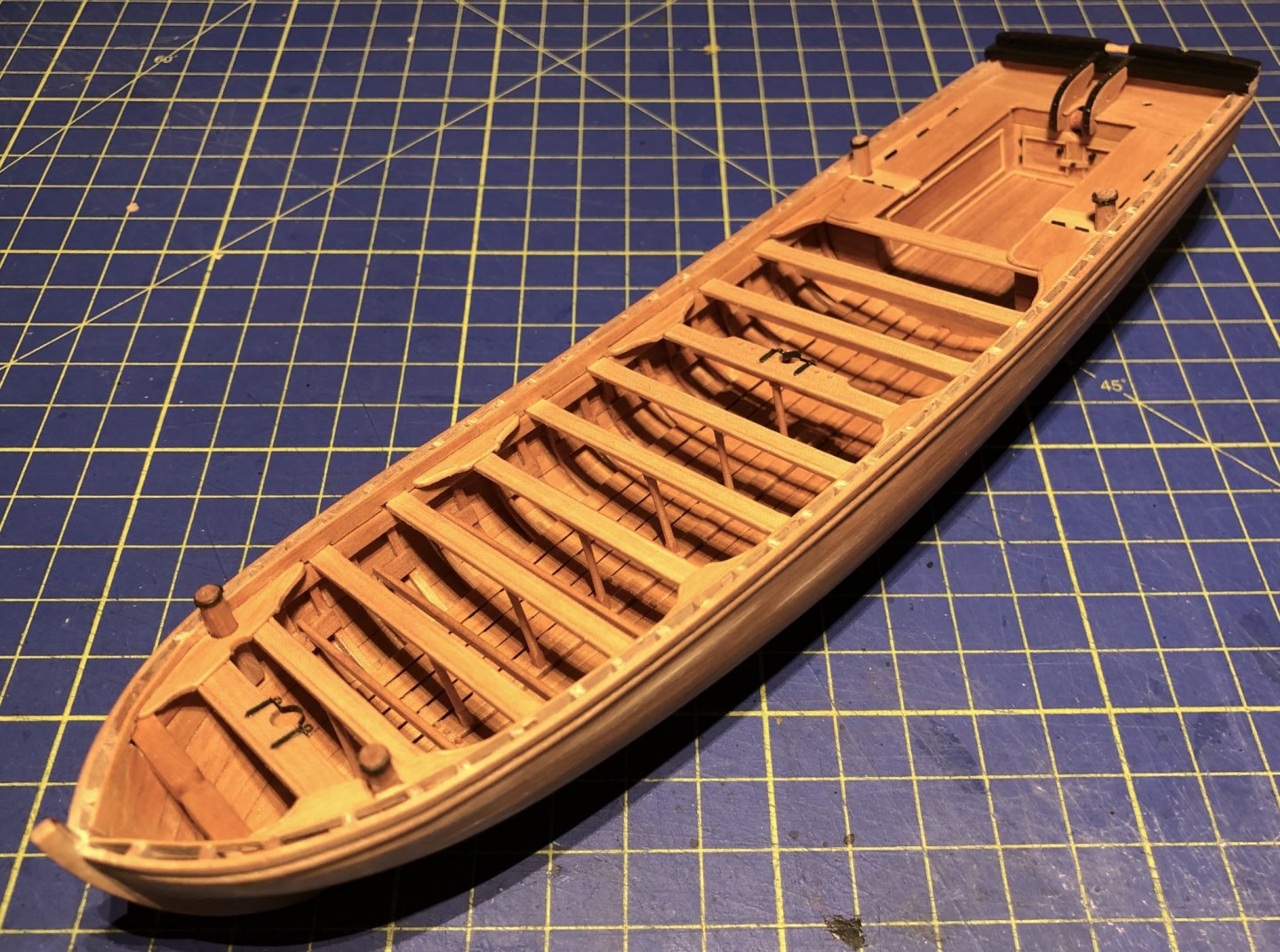
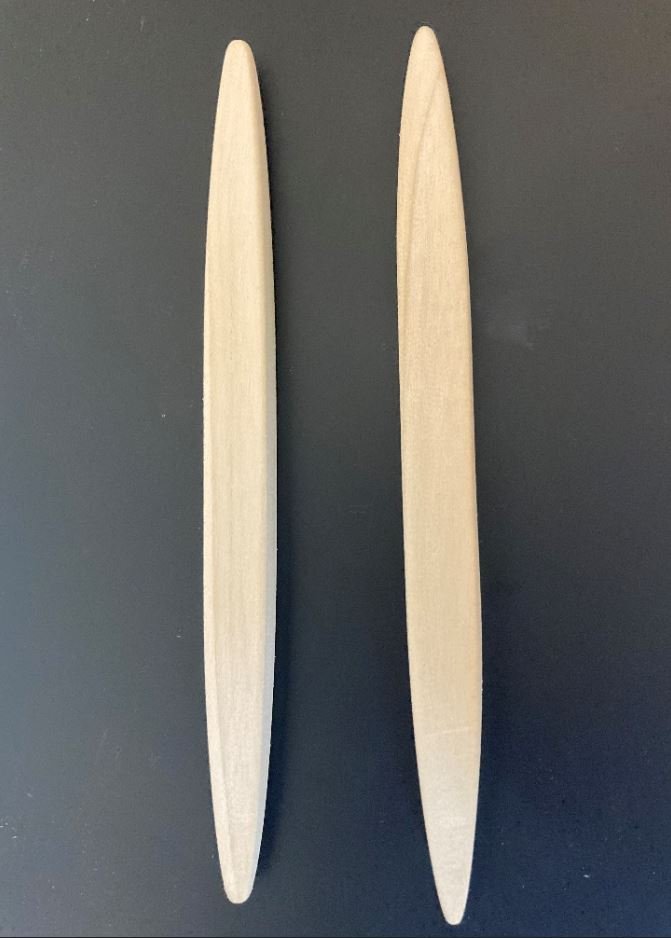
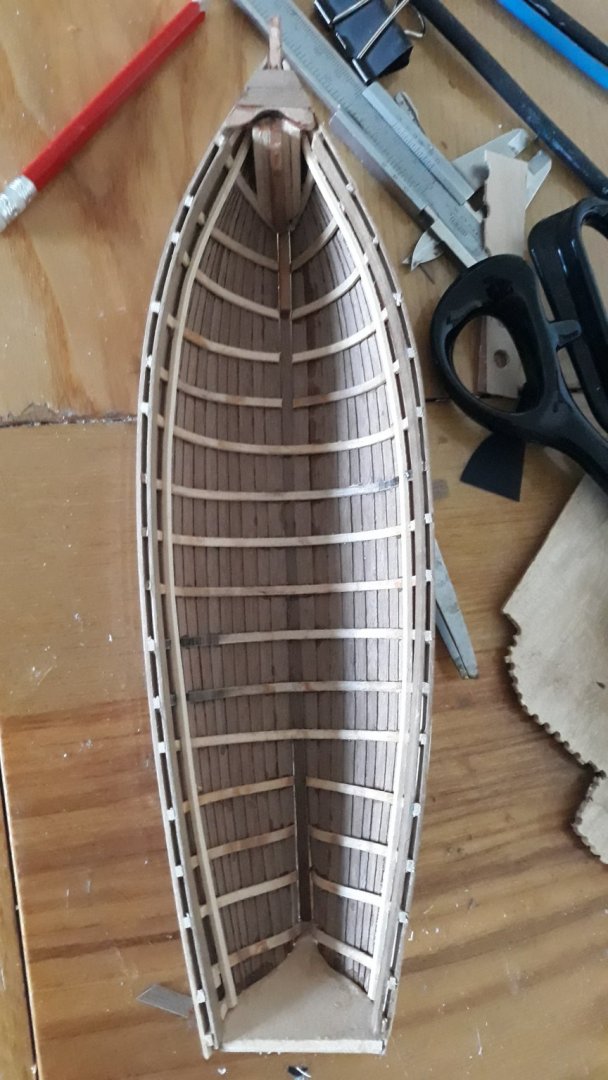
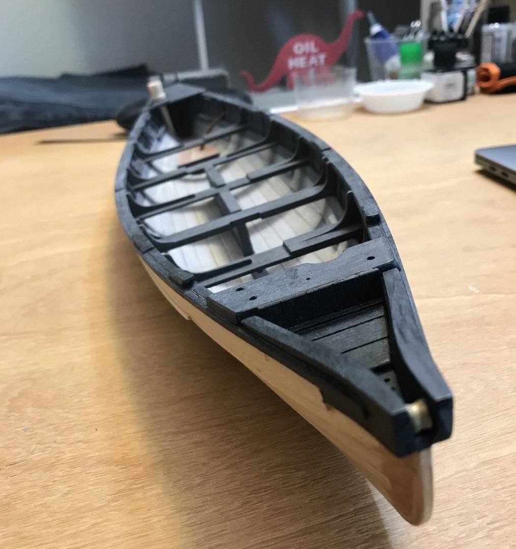
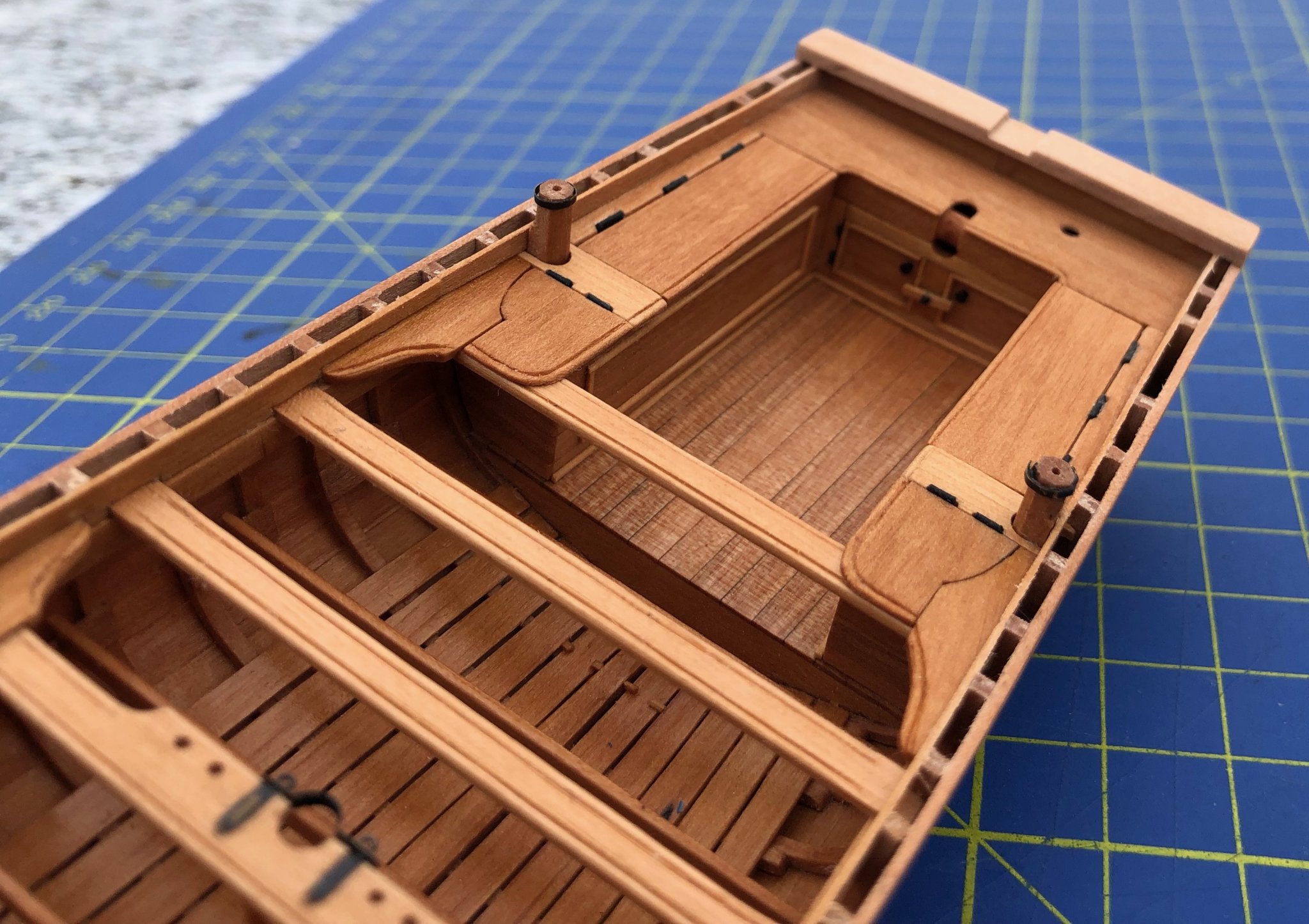
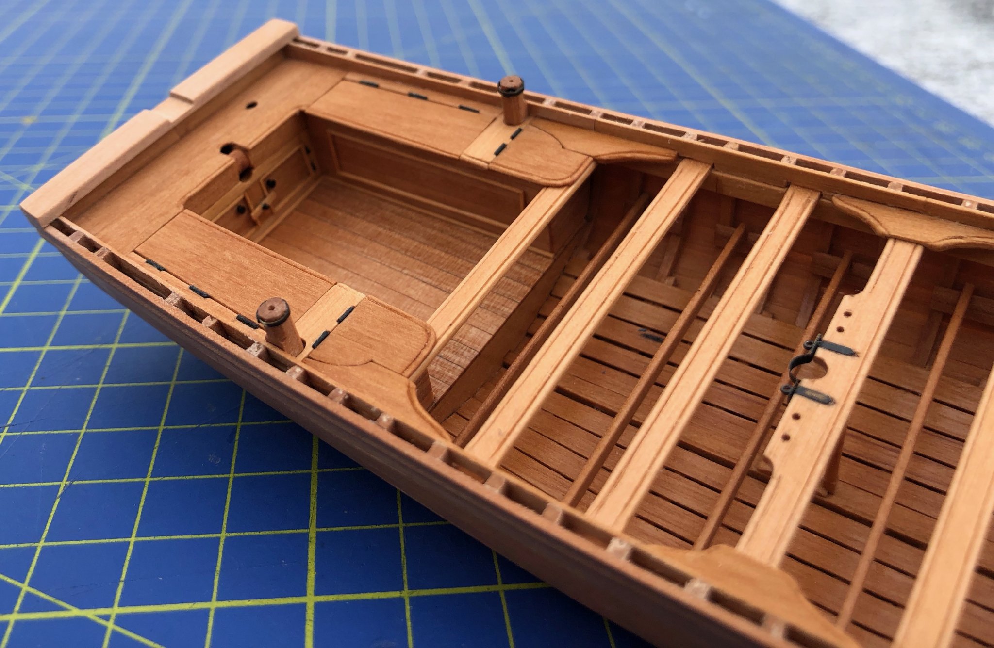
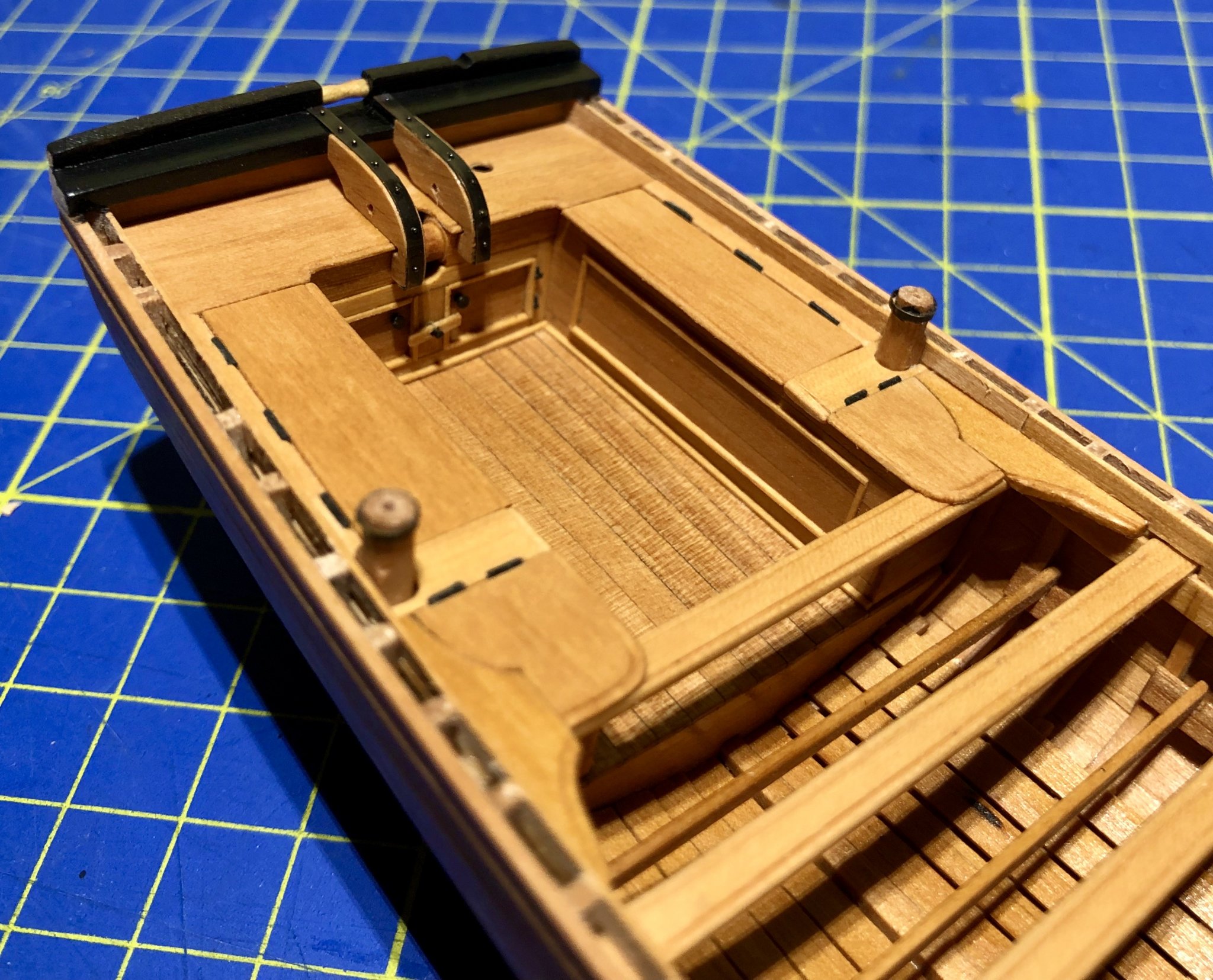
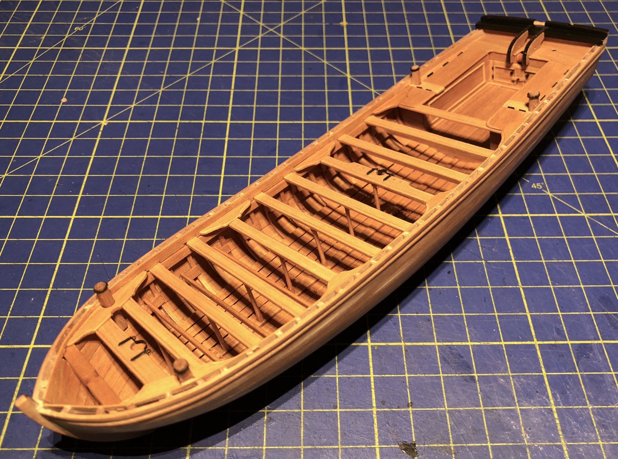
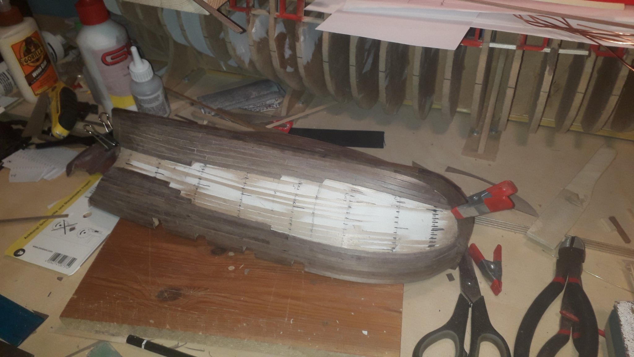
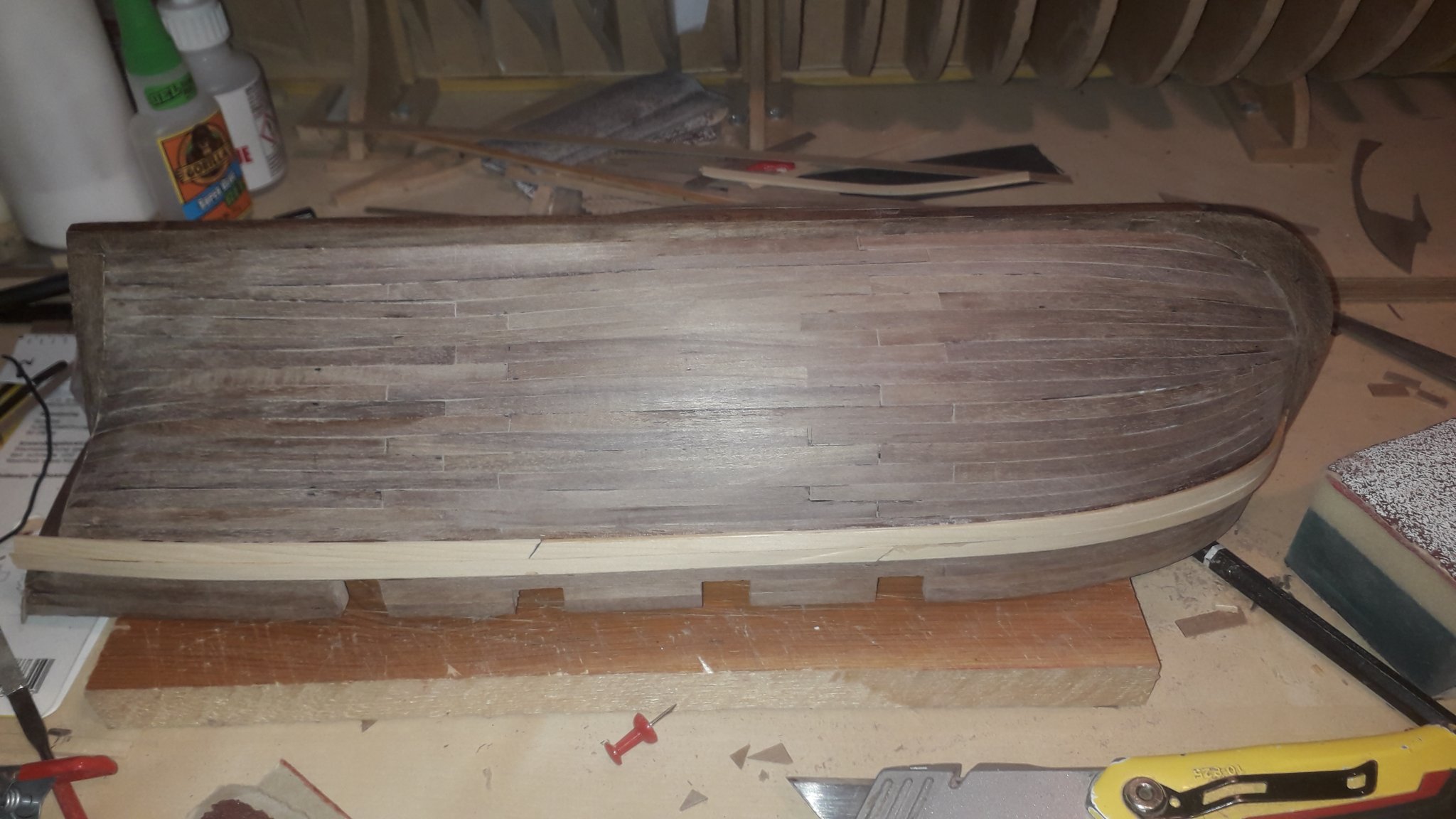
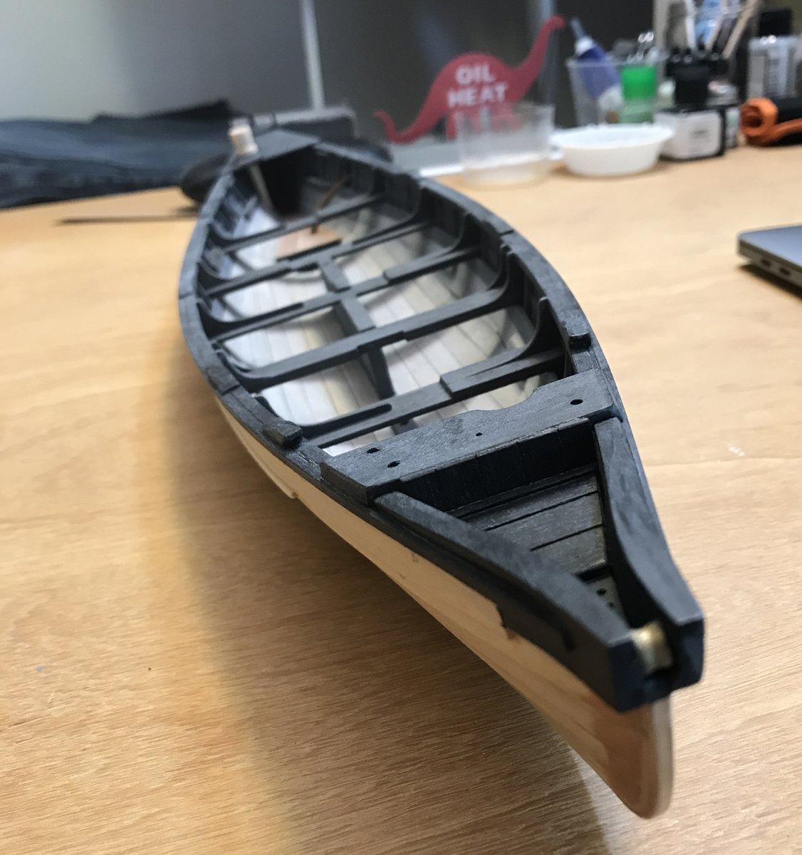
Dear all,
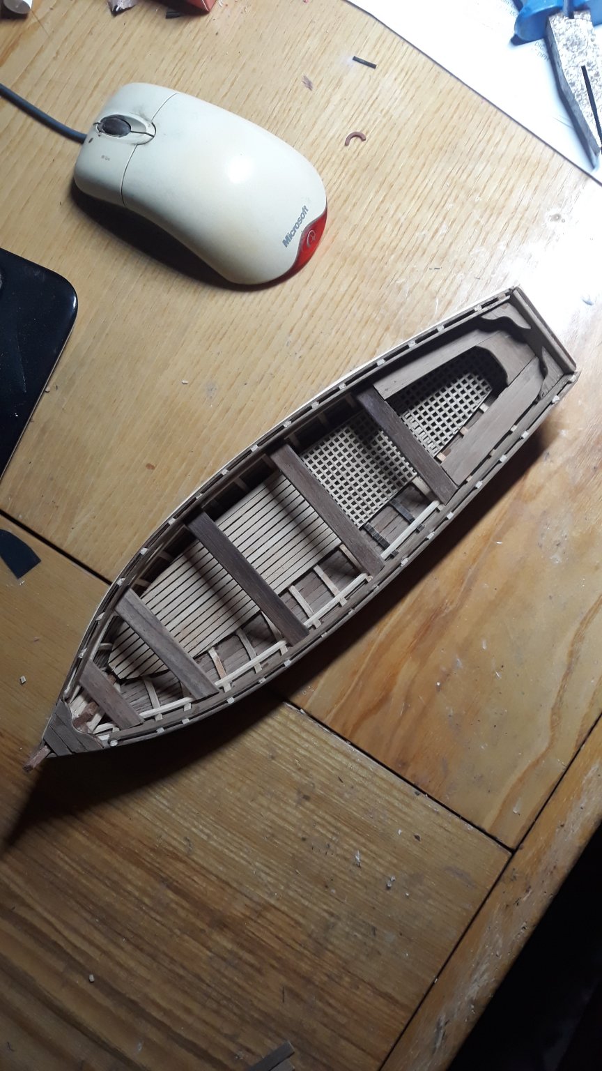
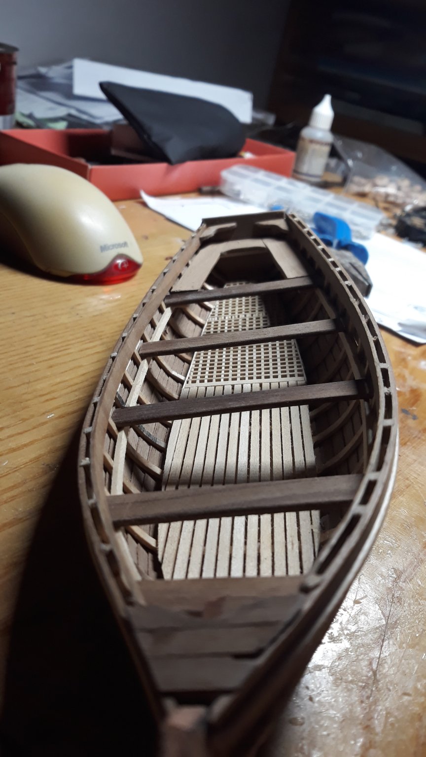
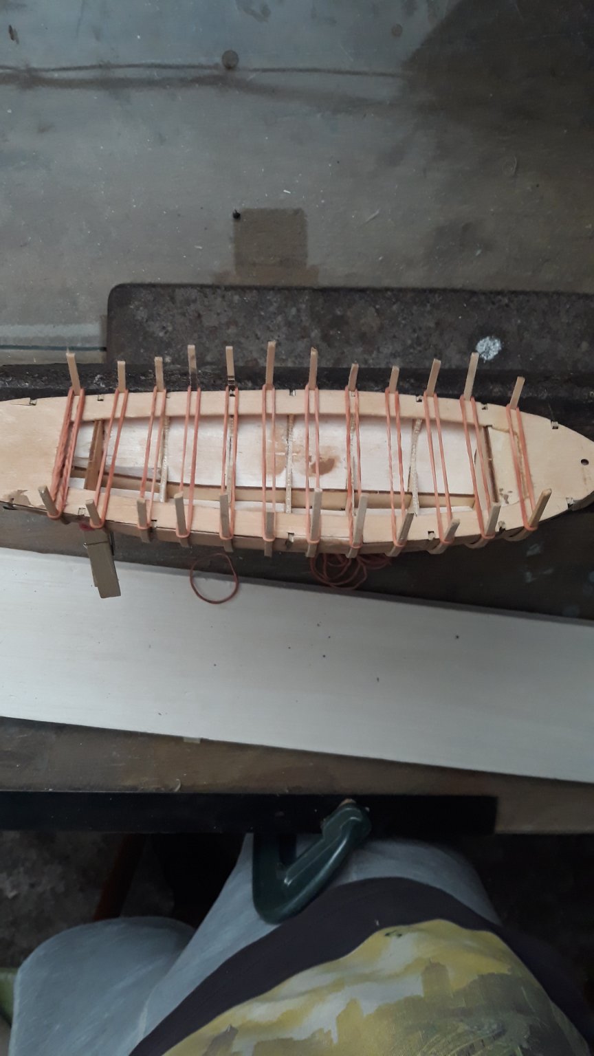
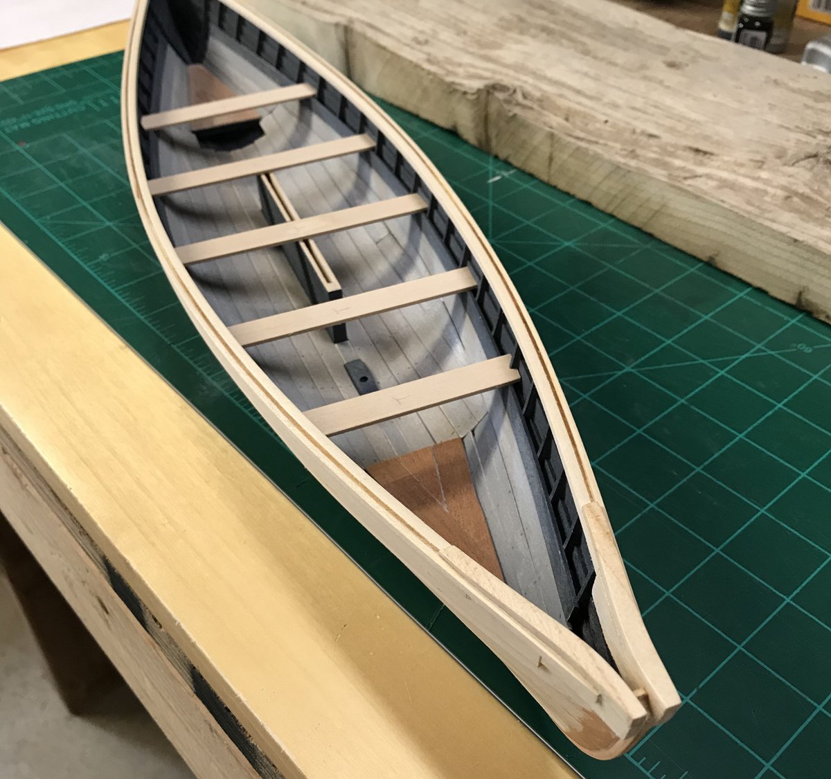
Last chapter, Captains gig.
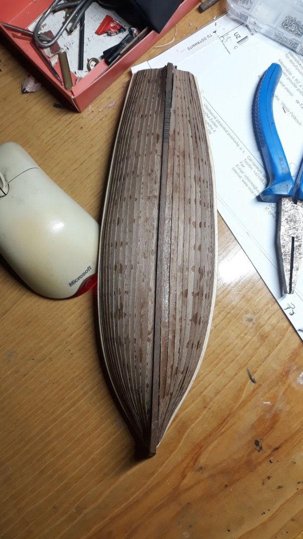
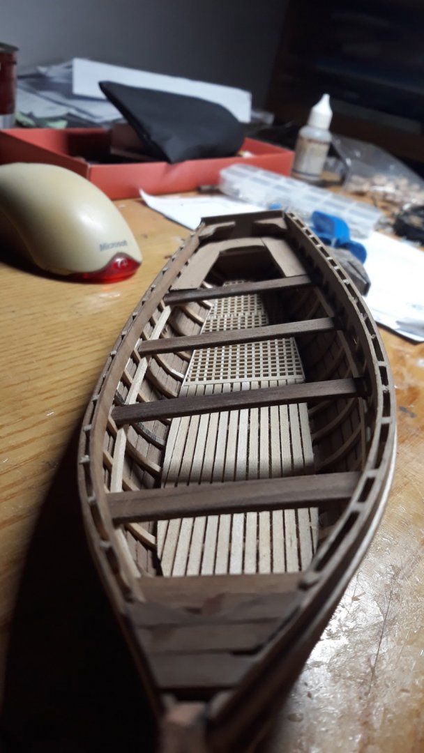
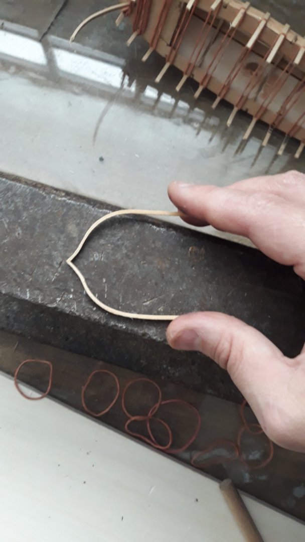
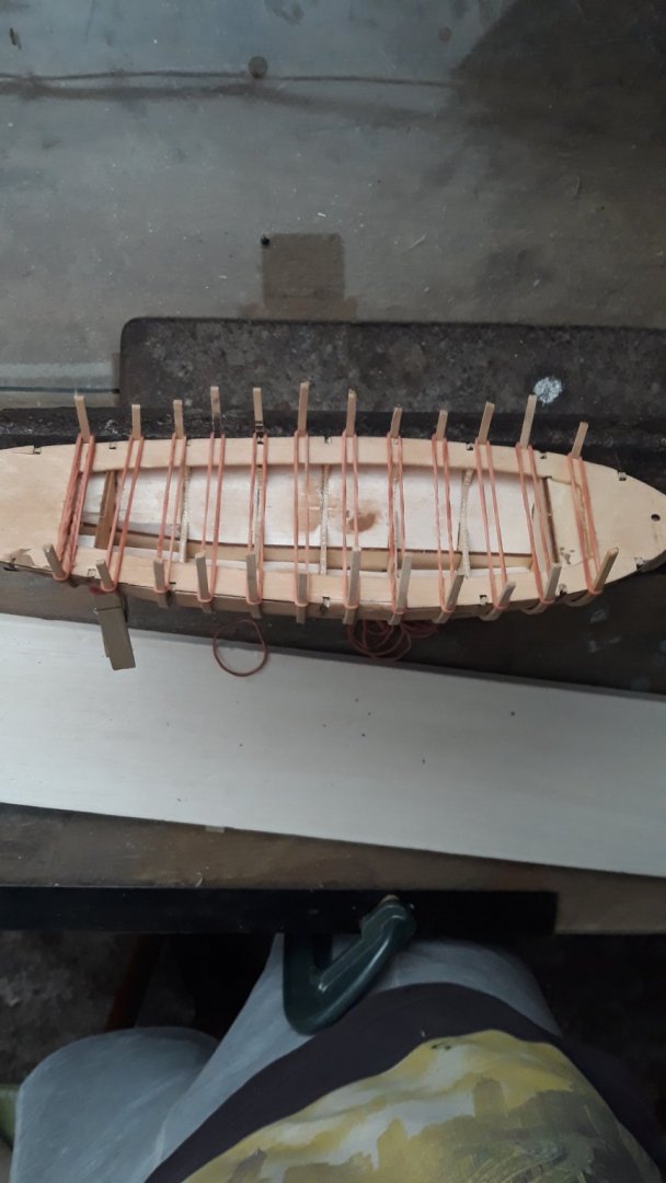
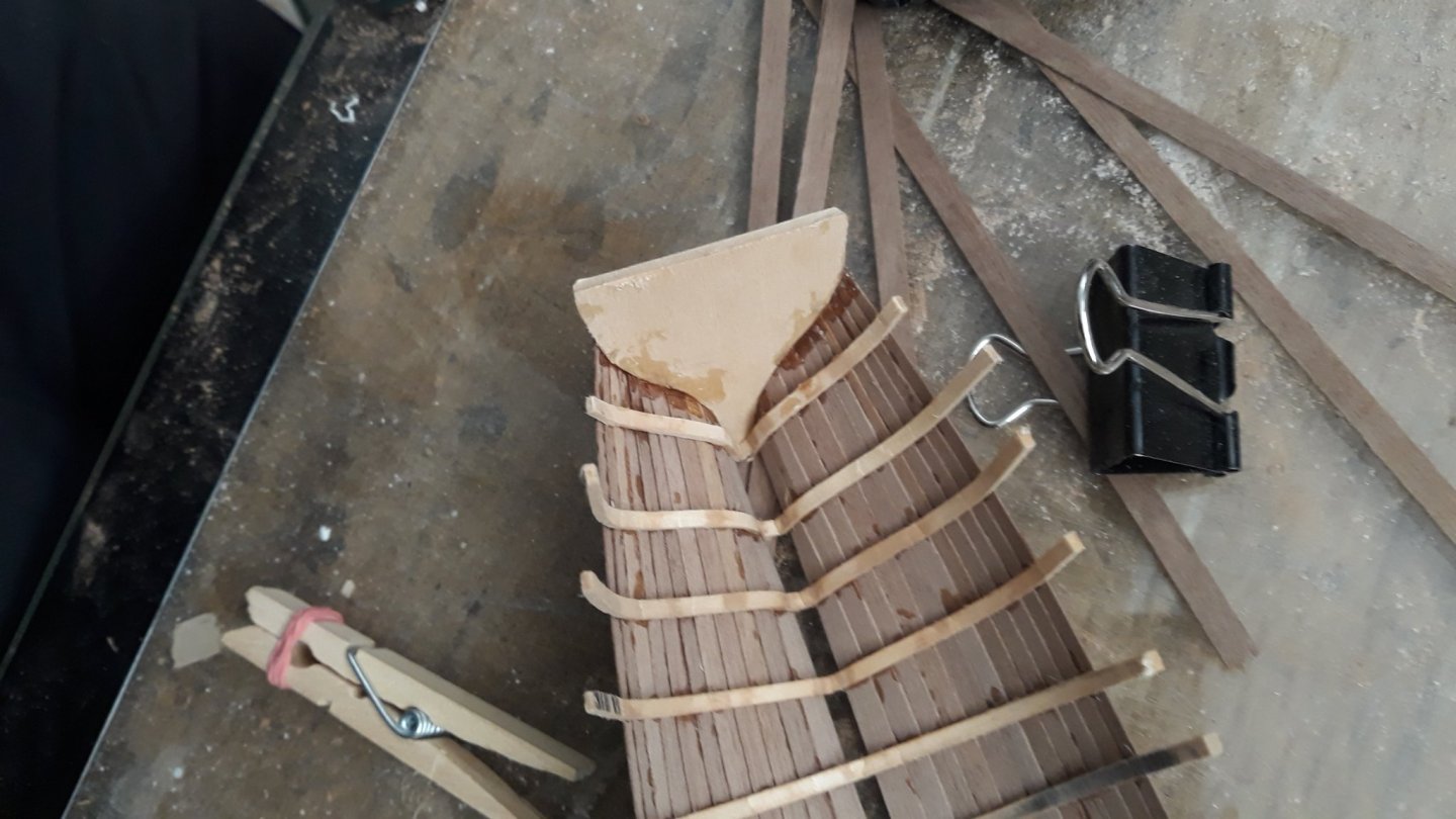
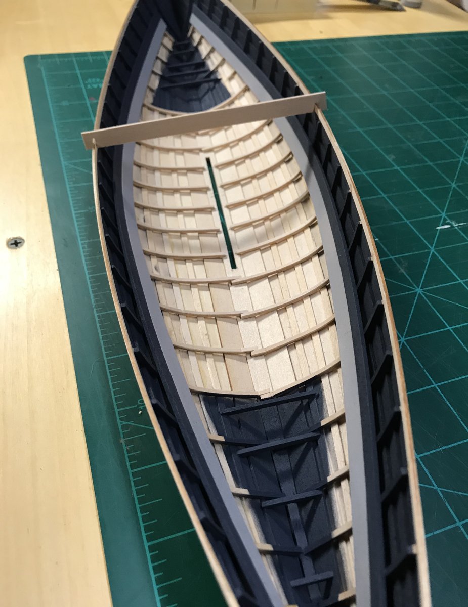
Irony of life do magics. Its strange that such small boat would bring me most joy of entire mammoth project on scale vessel. I have lits of small leftovers so i decided to make captains gig as a last point before wrap.
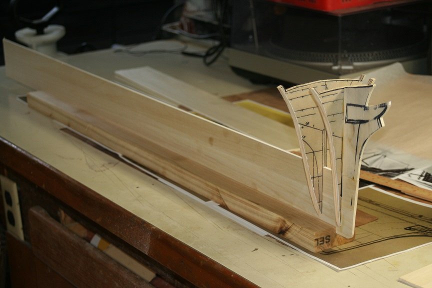
If someone is interested i can describe this method i tried. I observed mold works - so i bought small boat model for few euro. Completed bulkheads Filled up with balsa wood and voila - mold ready. - than i bended ribs/ to be oversized / and just simply clamped them with some rubber ring fasteners. / girls clamp their hairs with those/ ...
.....rest is usual as any clinker....
Even she is not symetrical gave me fun.

-
5 hours ago, rwiederrich said:
Vladimir...she sure is looking swell. Your planking work is exceptional. I applaud you for taking on such a large redo. I can only hope my planking of Glory of the Seas comes out nearly as well.
OH....I've never seen anywhere in your log about what, where, you plan on displaying this large model....what are your plans for her?
Rob
Thank you Rob for the liking and gratifying comment. Im sure you can do better i saw your striking sails and wonderful cabins..... its always place for getting better, i was not particularly picky. One thing i ensure was i didnt want oil varnish to change color to amber..so i obtained one that doesnt color wood. Im pleased for almost white floors though...
.
as this project taught me to be humble observing others work, well well, good question of placing her.wanna truth? I dont want to keep her for some reasons rather let her go.... I wish more people could see her so i will try that route first not sure what route that would be..and if not succeed, i will try to offer her if there was sign of interest somehow .
") and if not i will keep her. will see.. and now last chapter so i can catch up with glory of the seas fanclub. V.
and if not i will keep her. will see.. and now last chapter so i can catch up with glory of the seas fanclub. V.
-
3 hours ago, Bruma said:
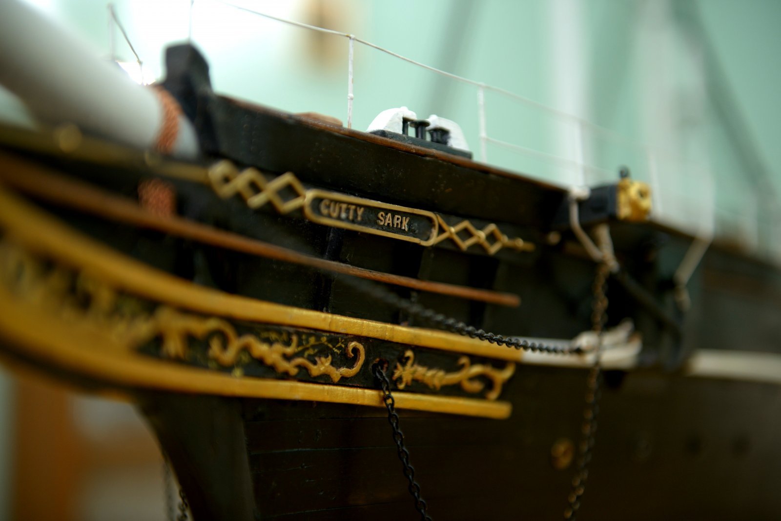
Vladimir, your Cutty Sark is growing wonderfully!
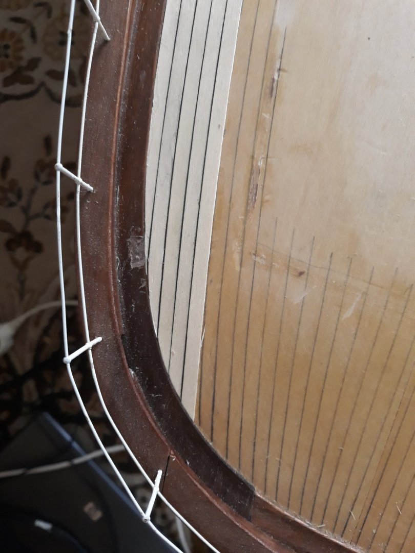
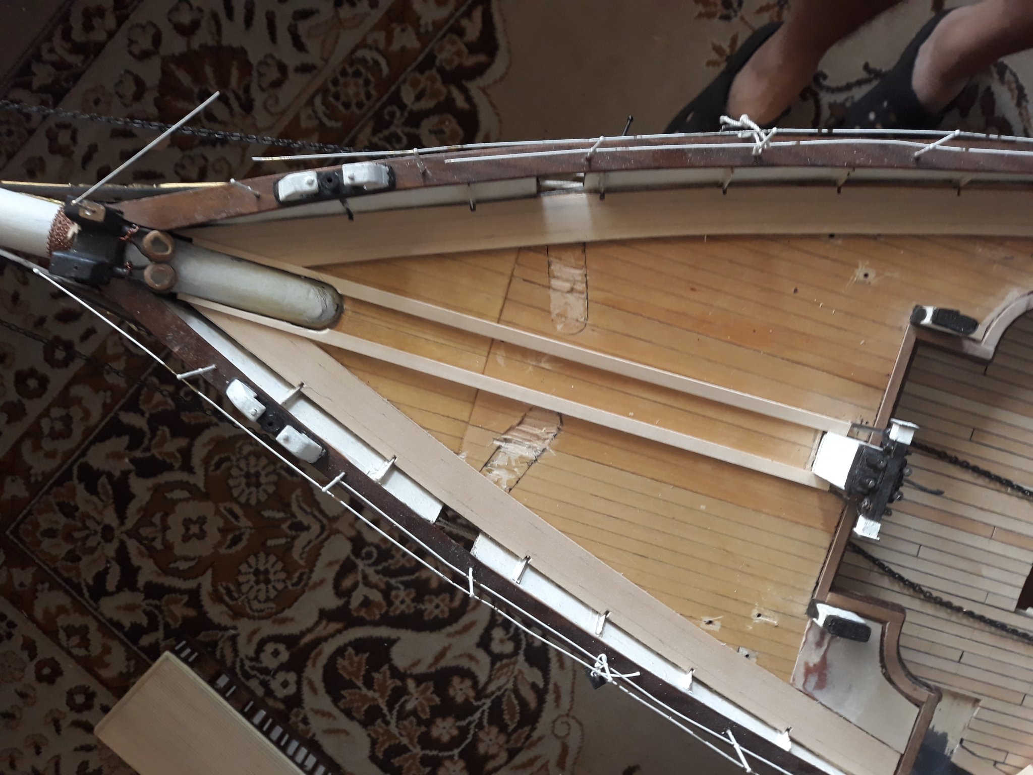
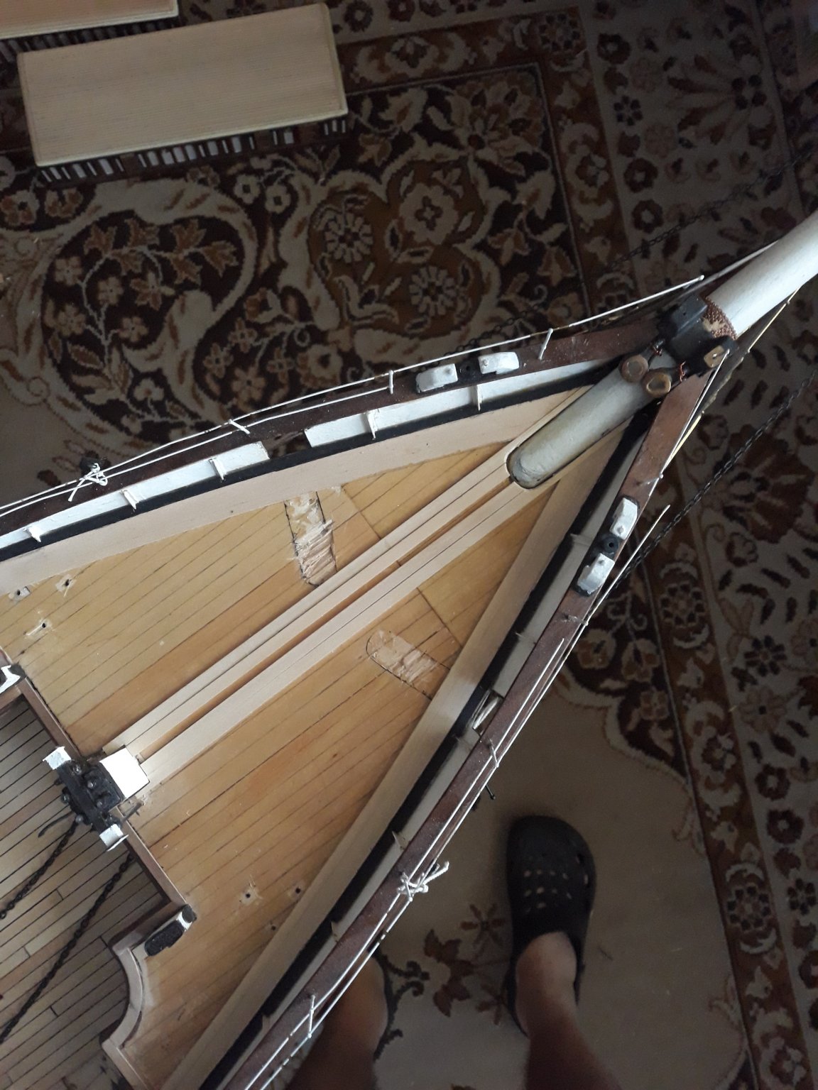
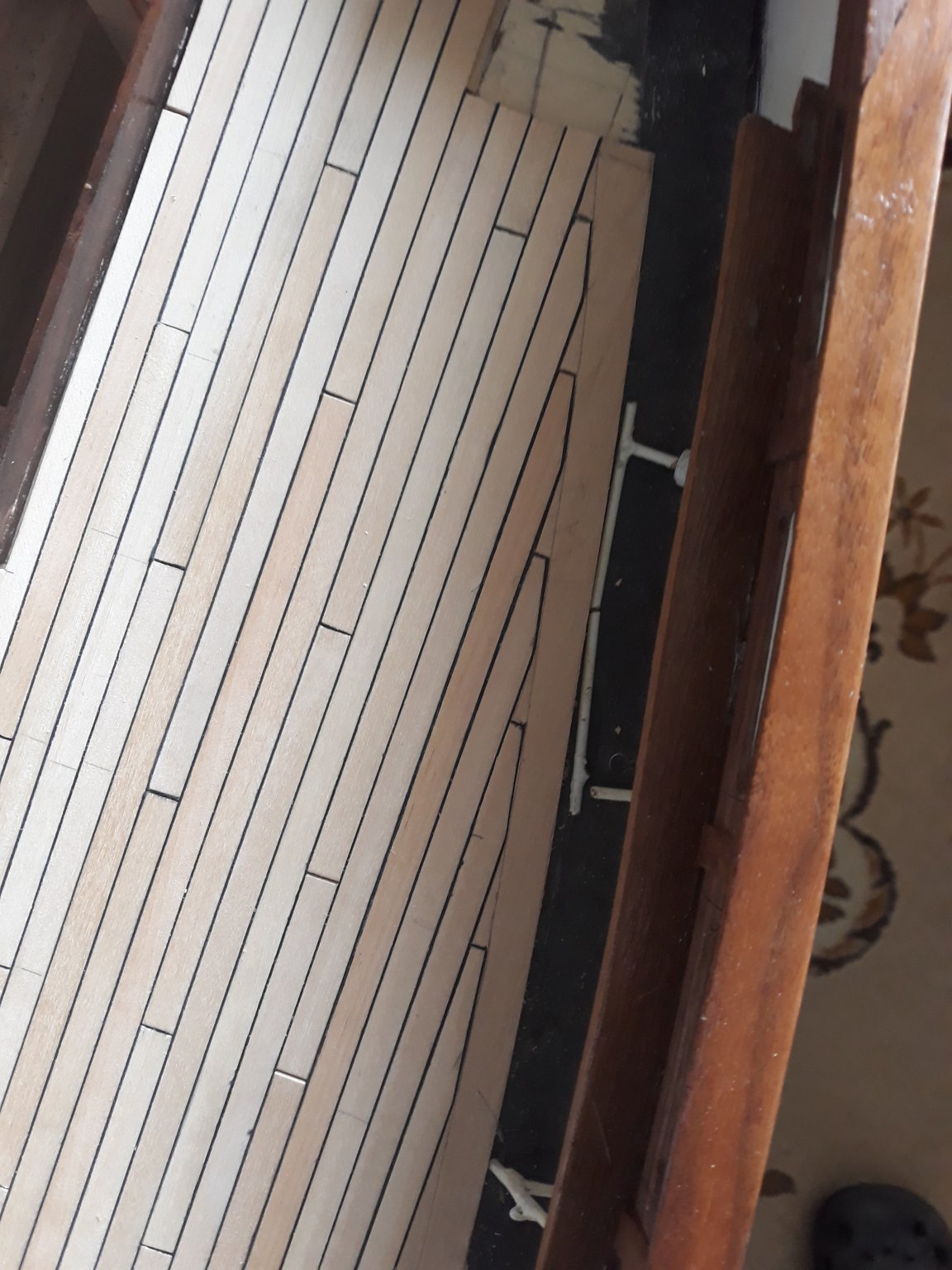
Looking at your last pictures, there is a detail that catch my attention: the stern deck planking pattern.
You mentioned, "Poop deck floor is properly curved along the gangway...and met in center/ probably not like prototype but...well..."
Why did you choose to use this specific pattern?
In Campbell's plans they are straight and parallel.
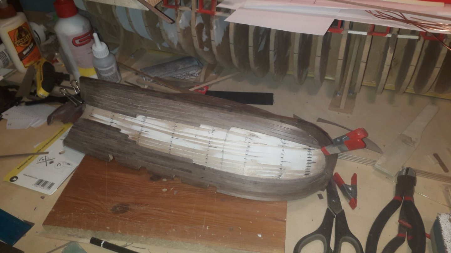
Just to clarify, mine is not a criticism, your planking is really nice and well done, especially in this difficult area. I'm now a Cutty Sark addicted and I would like to know it better, any source of information is welcome. ☺️Hi Bruma, thank you for great comment and good observation. first off, if you look ver carefully sou can see that curved planks should follow not only line of gunwales but also poop deck itself. therefore there is slight curvature discrepancy of stern towards end i am aware of and sharp eye sees it...even though i was correcting it. that pattern is something you may call laziness prbobably. as it was easiest how to finish it quickly. not really something to be followed, campbell panks are being straightened towards center and possibl cut narrow , buI just have basically enough after more than 3000 hours of building i consider it feature not design flaw :))) . there is wheelbox laying ot center anyway ao it is not visible at all anyway. i just have enough. i am finishing captains gig and that would be all.
need to move on as i do not have more energy . i will not even finish rudder at this stage as I dont have capacity to weld such big hinges...so i decided that will be done maybe next year . thanks for liking I believe there is always room for upgrading, but i learnt a lot on their mammoth
-
-
very nice work on deadeyes
Bruma . lovely .
- shipman and FrankWouts
-
2
-
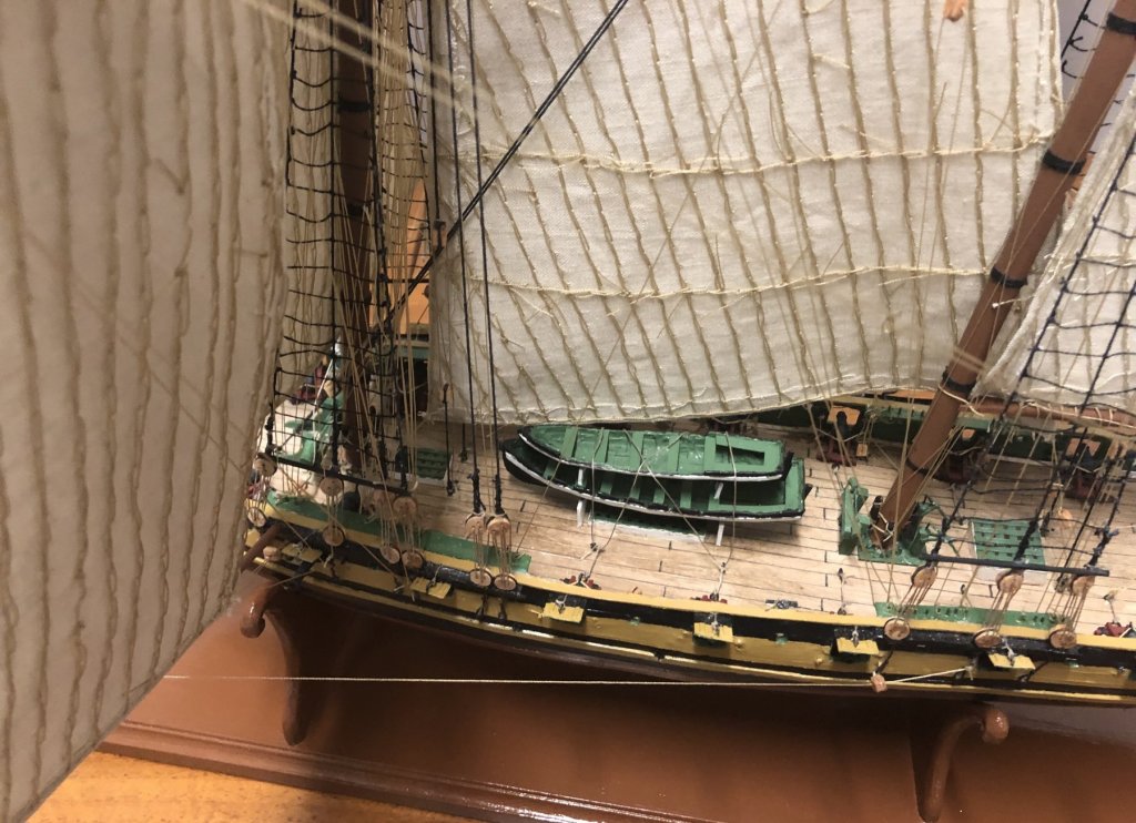
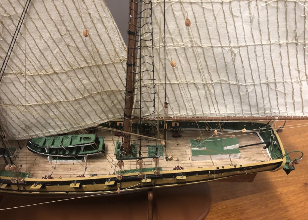
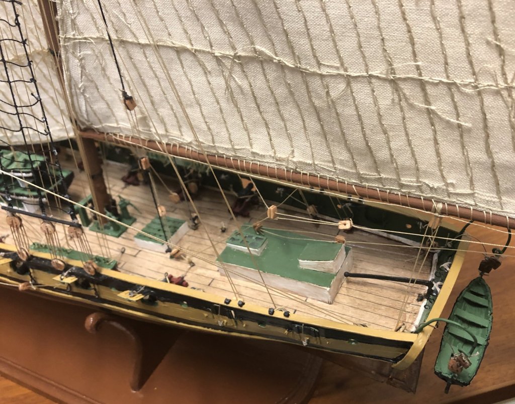
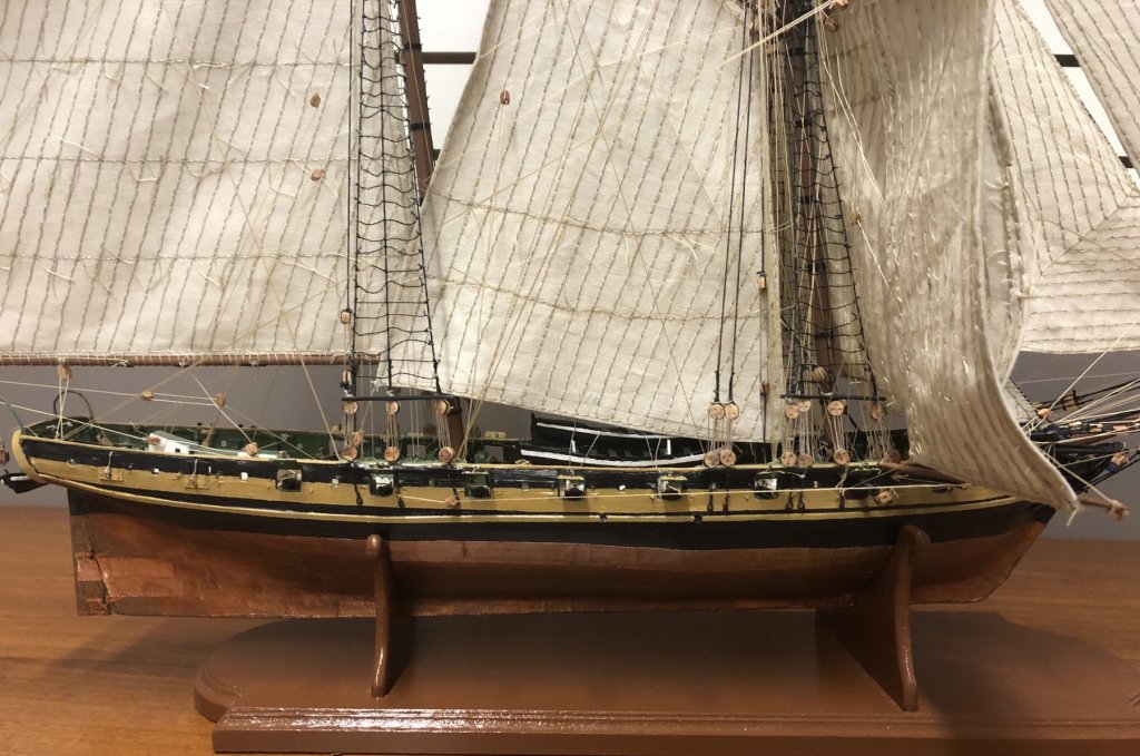
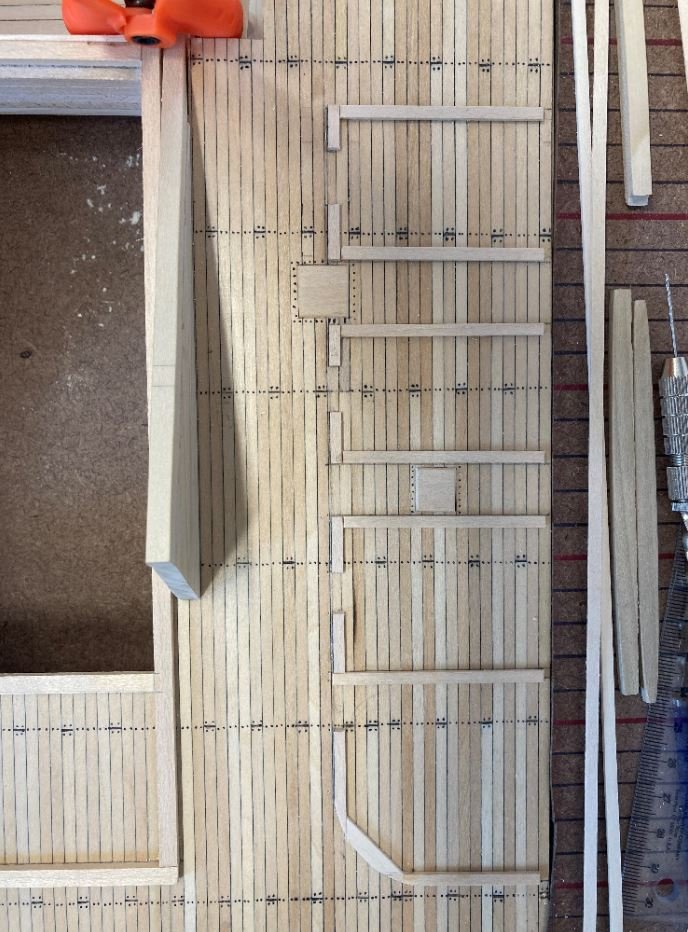
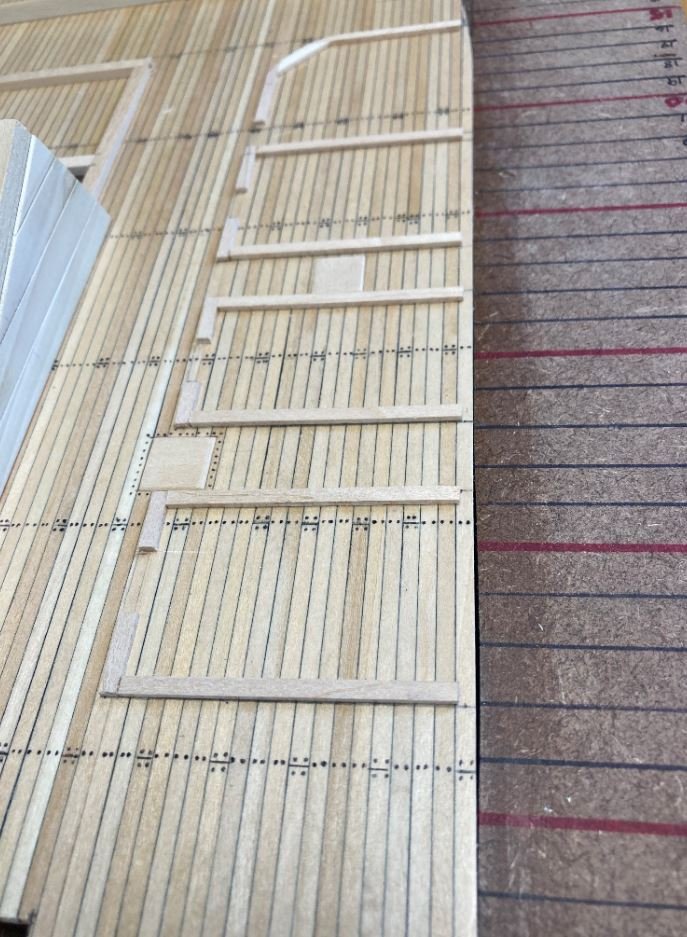
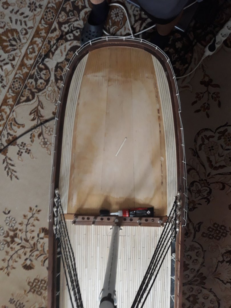
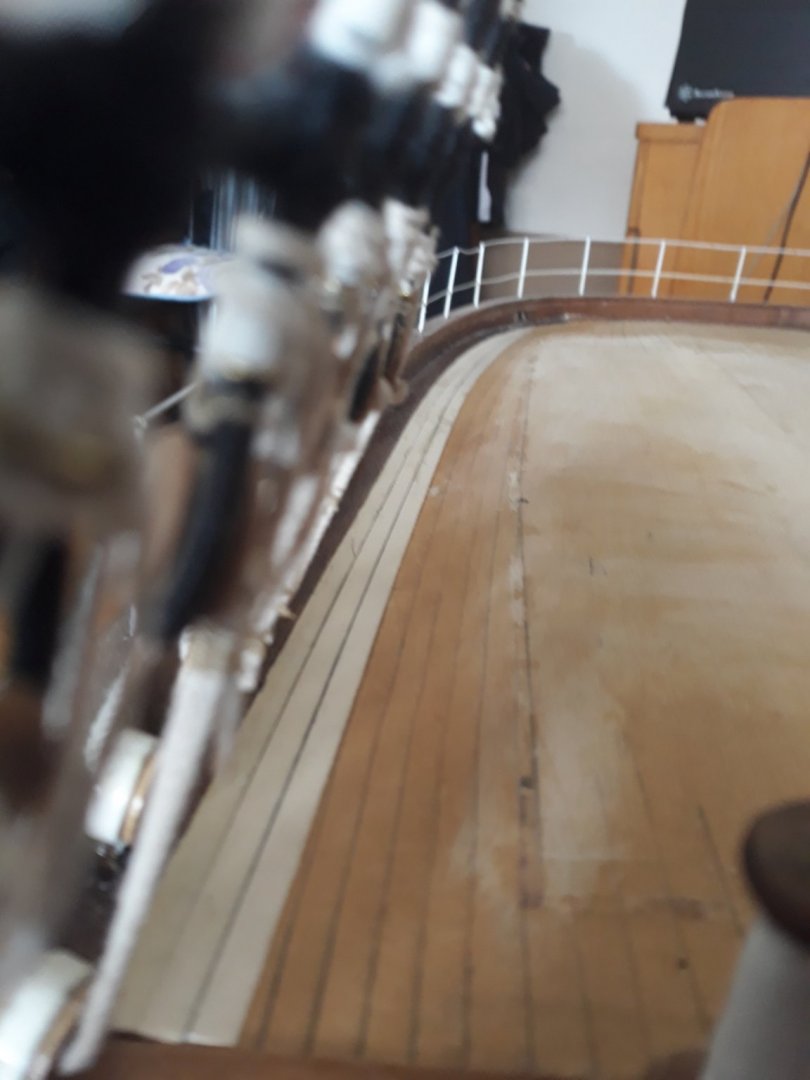
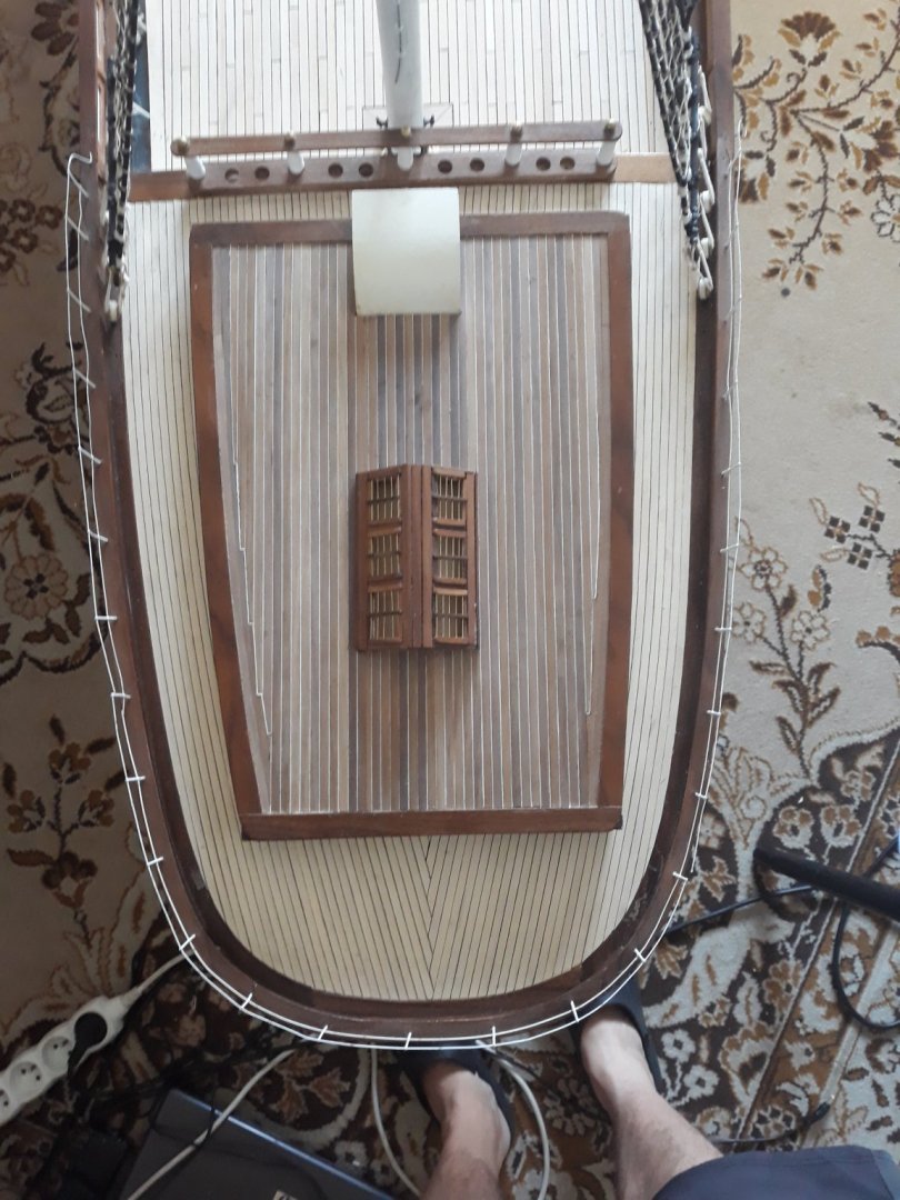
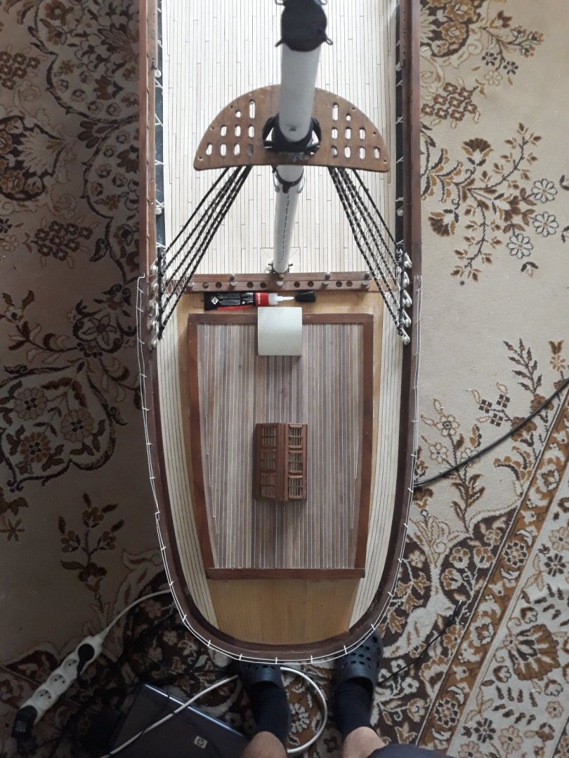
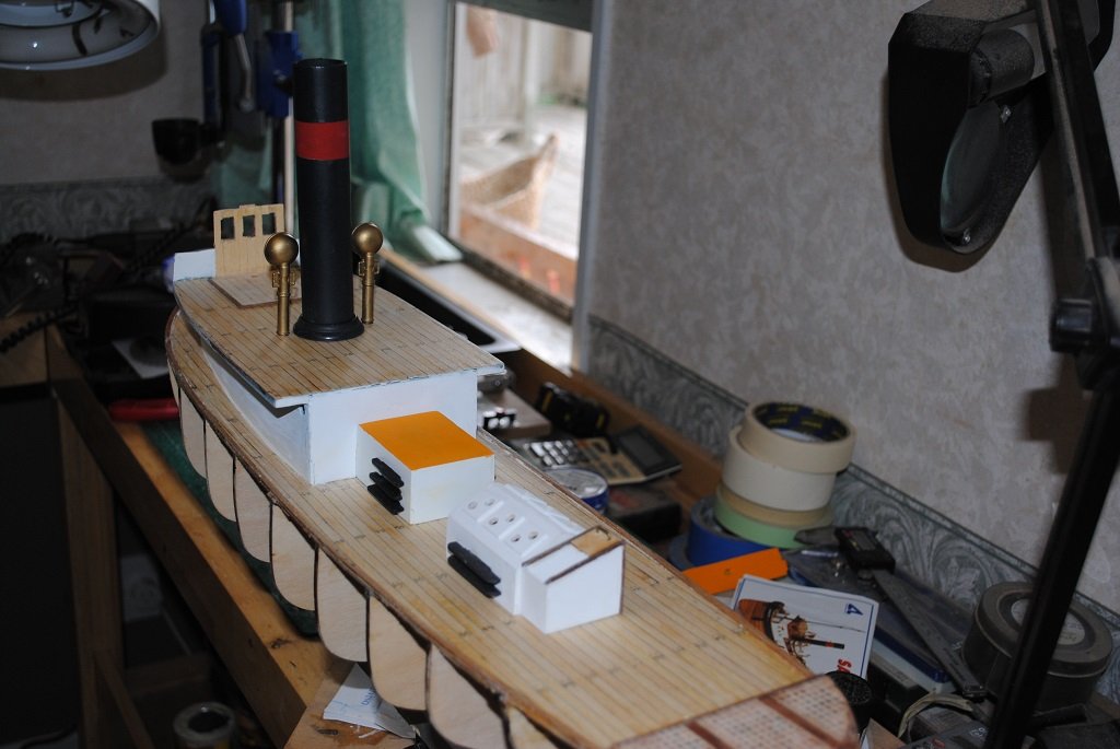
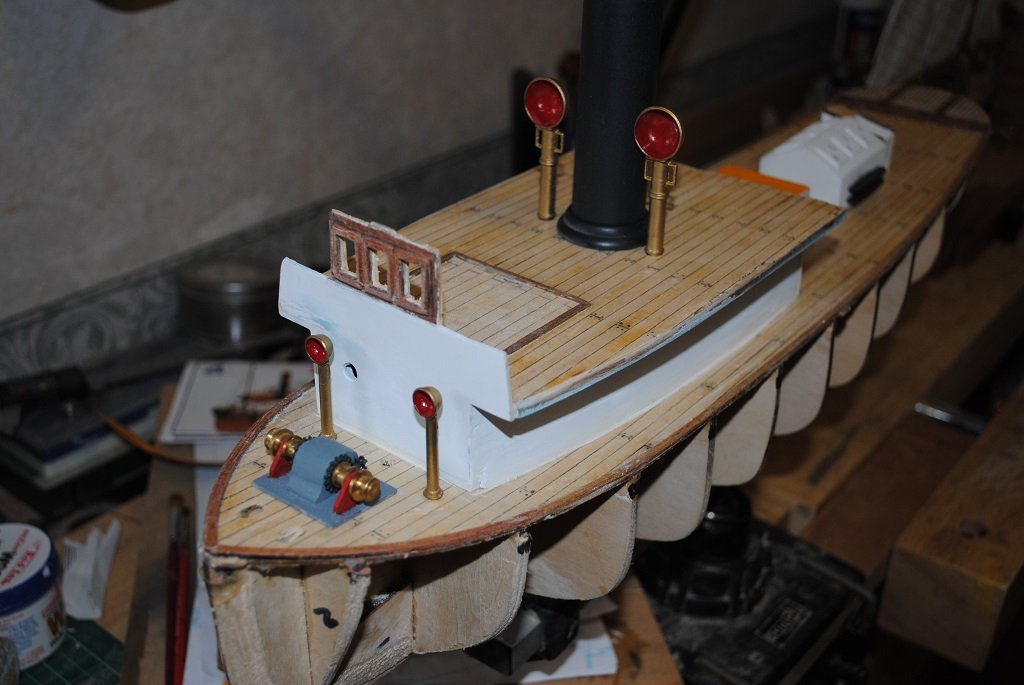
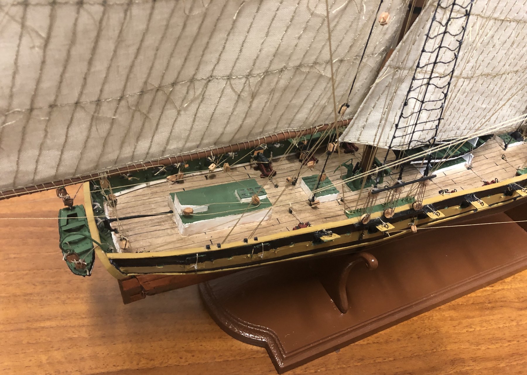
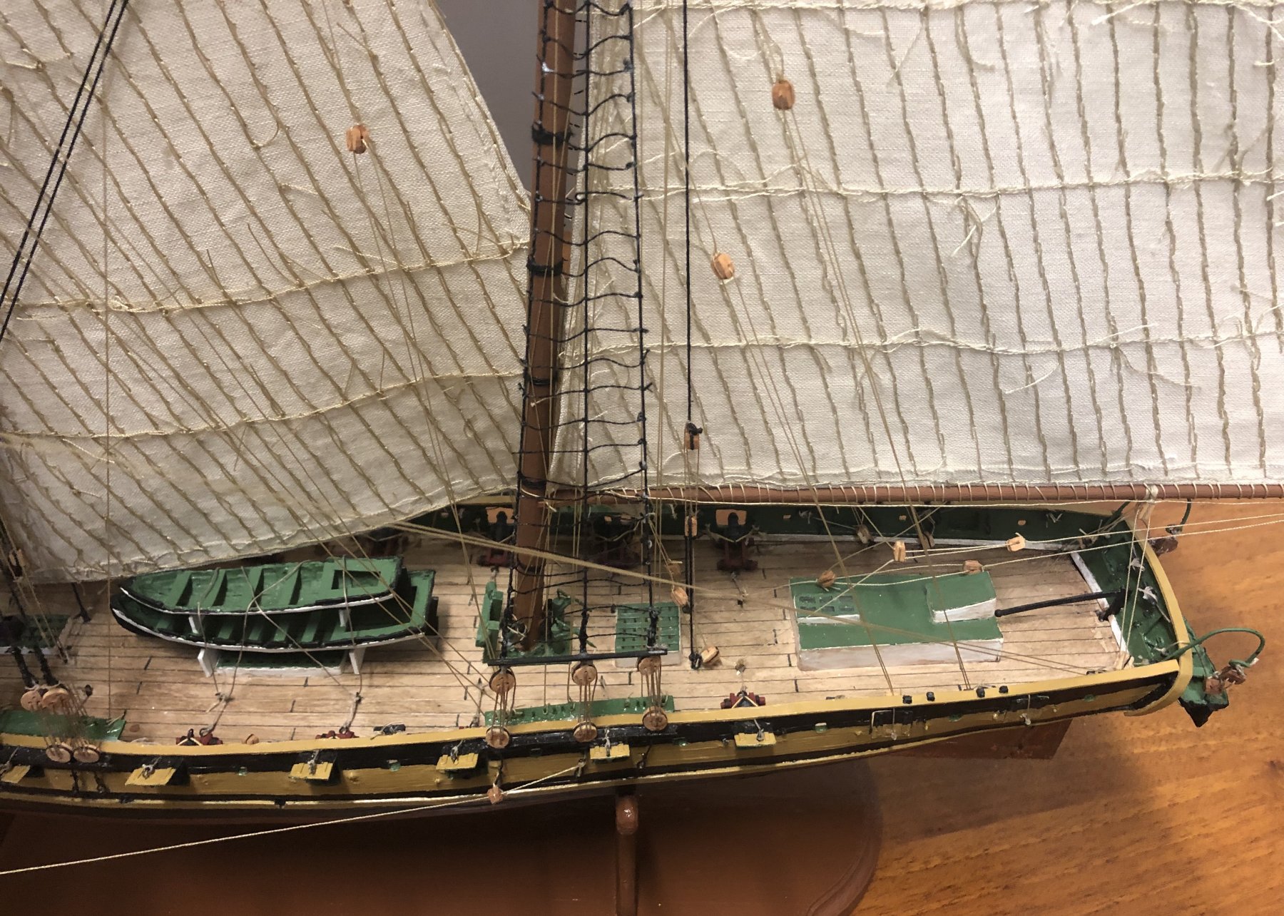
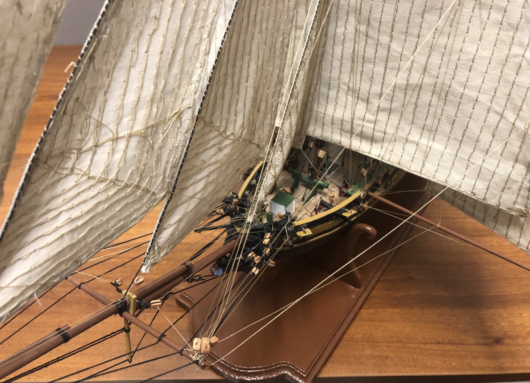
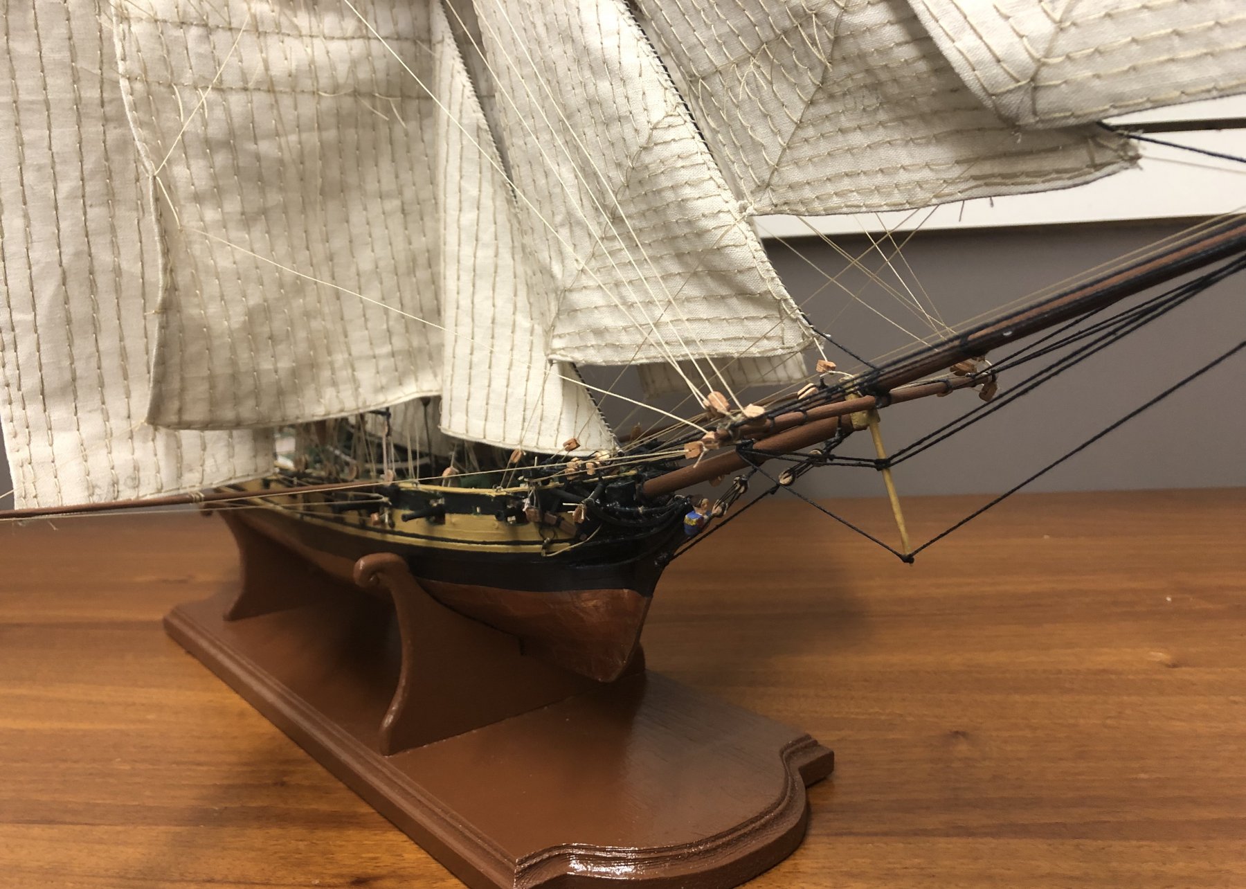
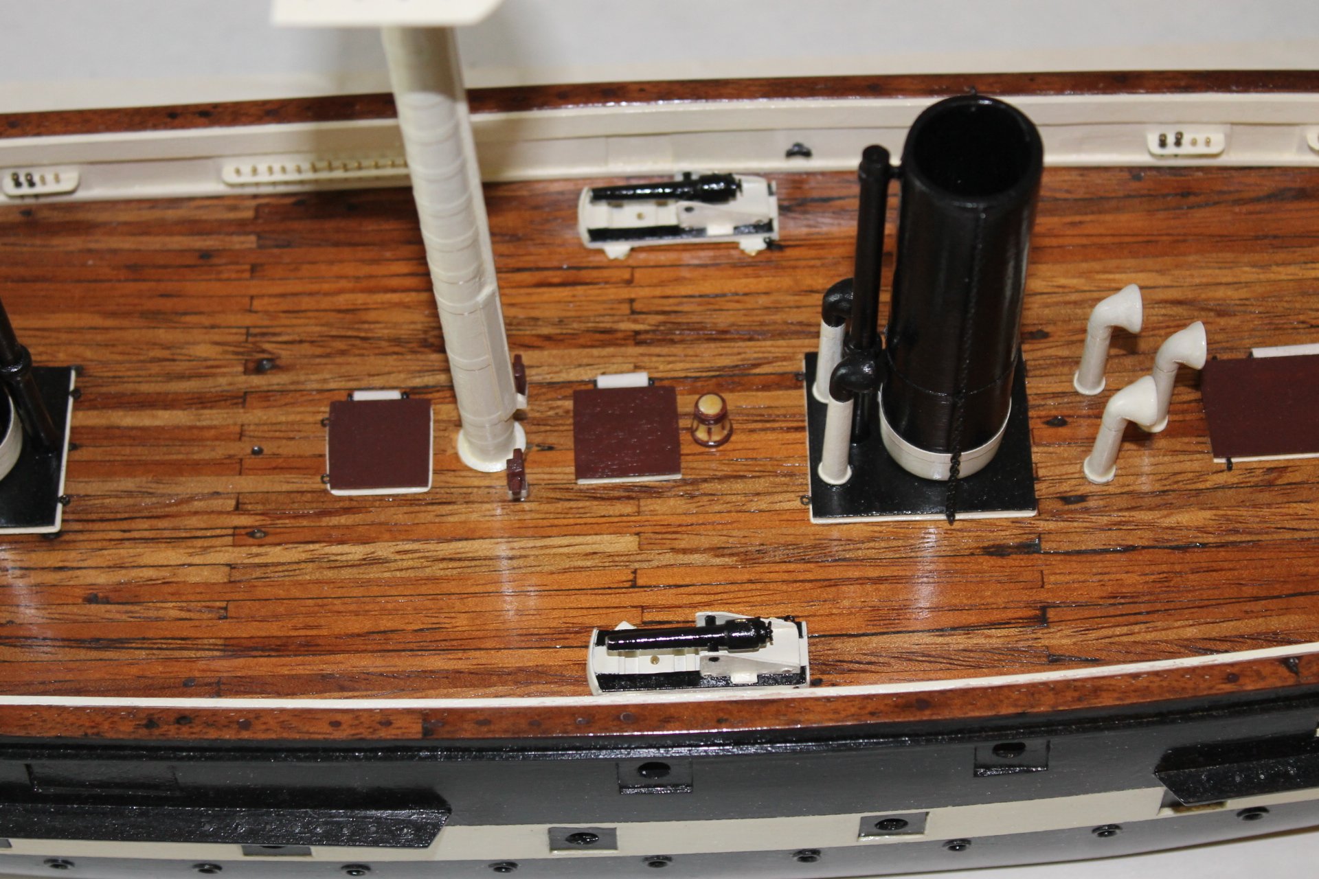
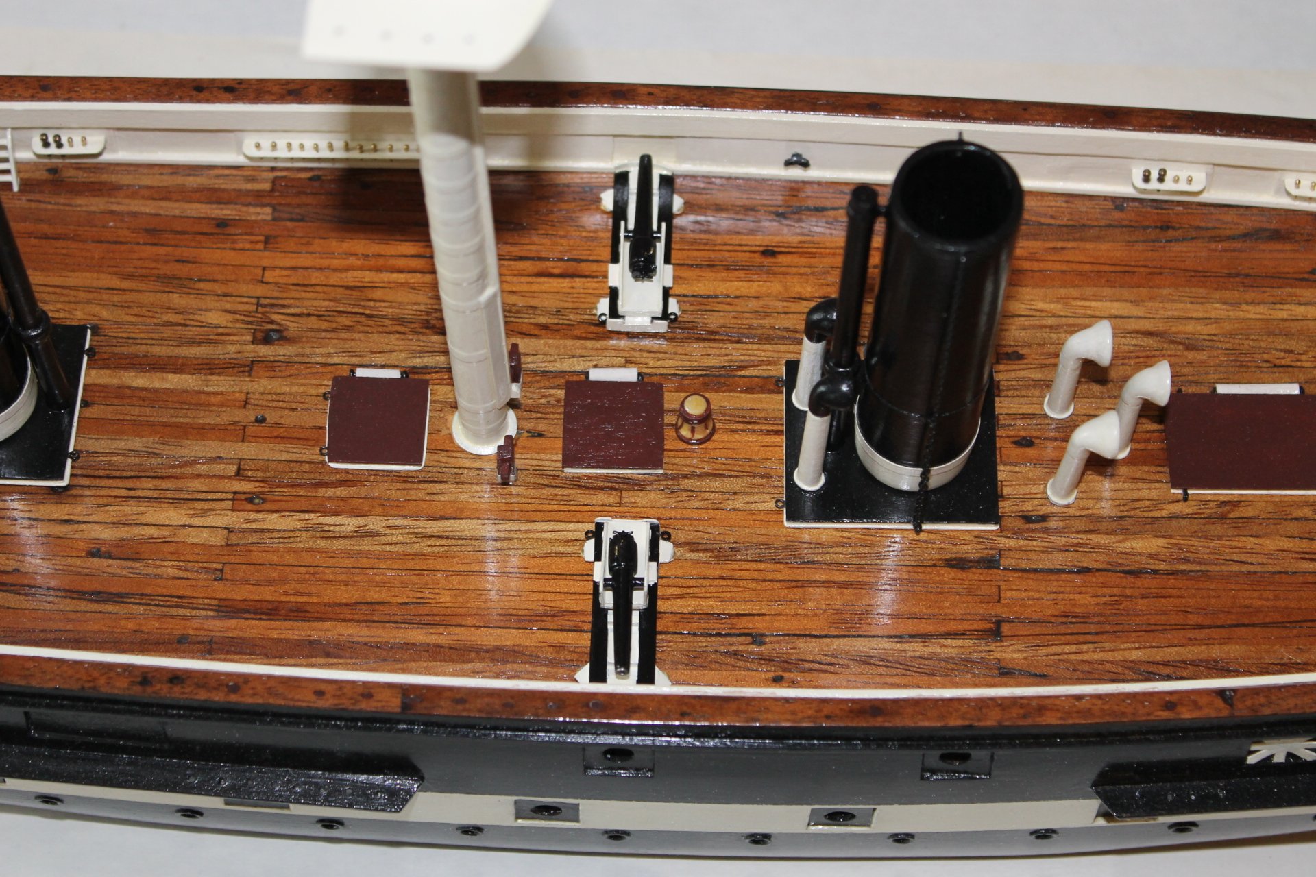
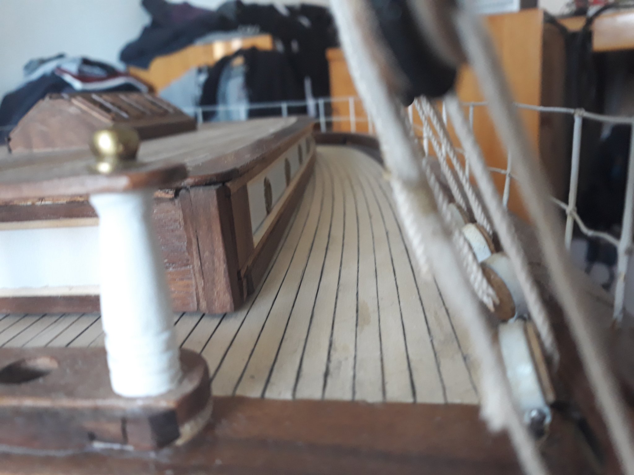
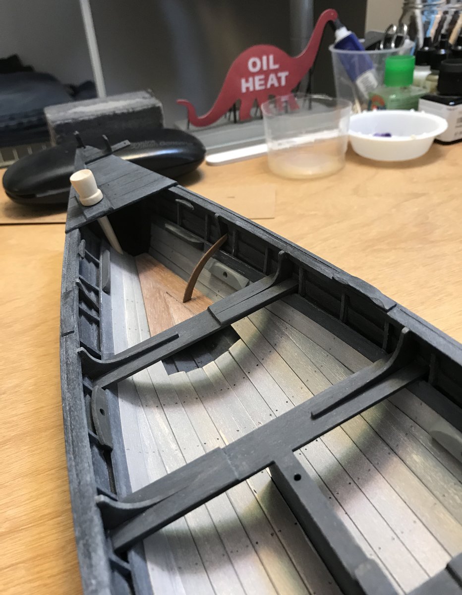
Good day everyone,
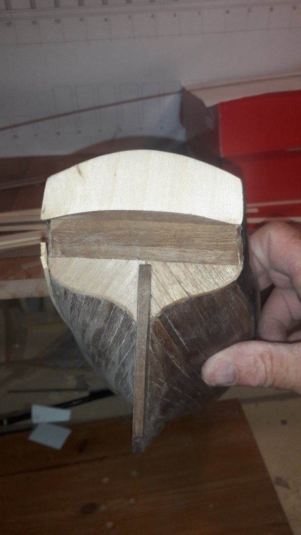
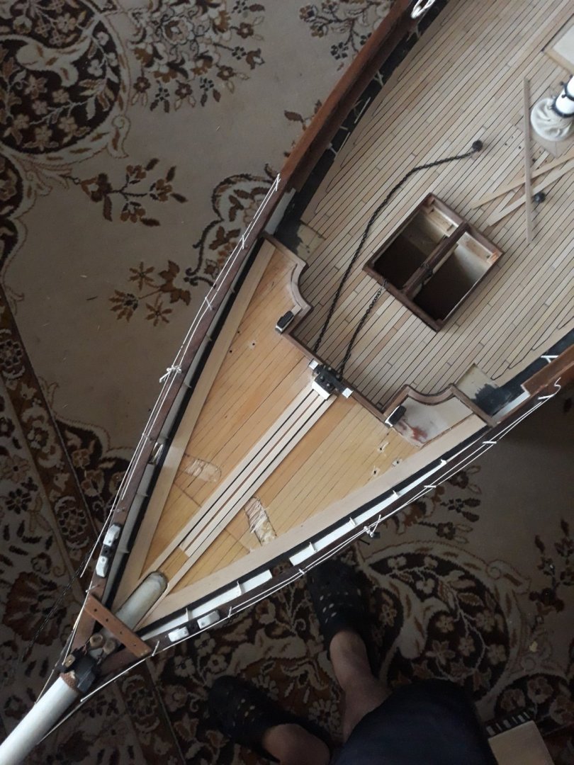
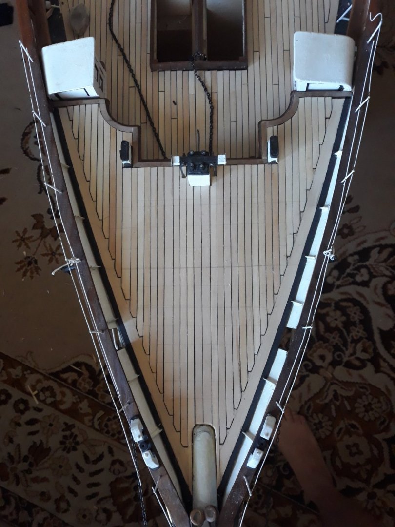
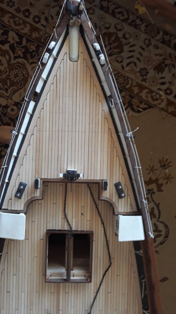
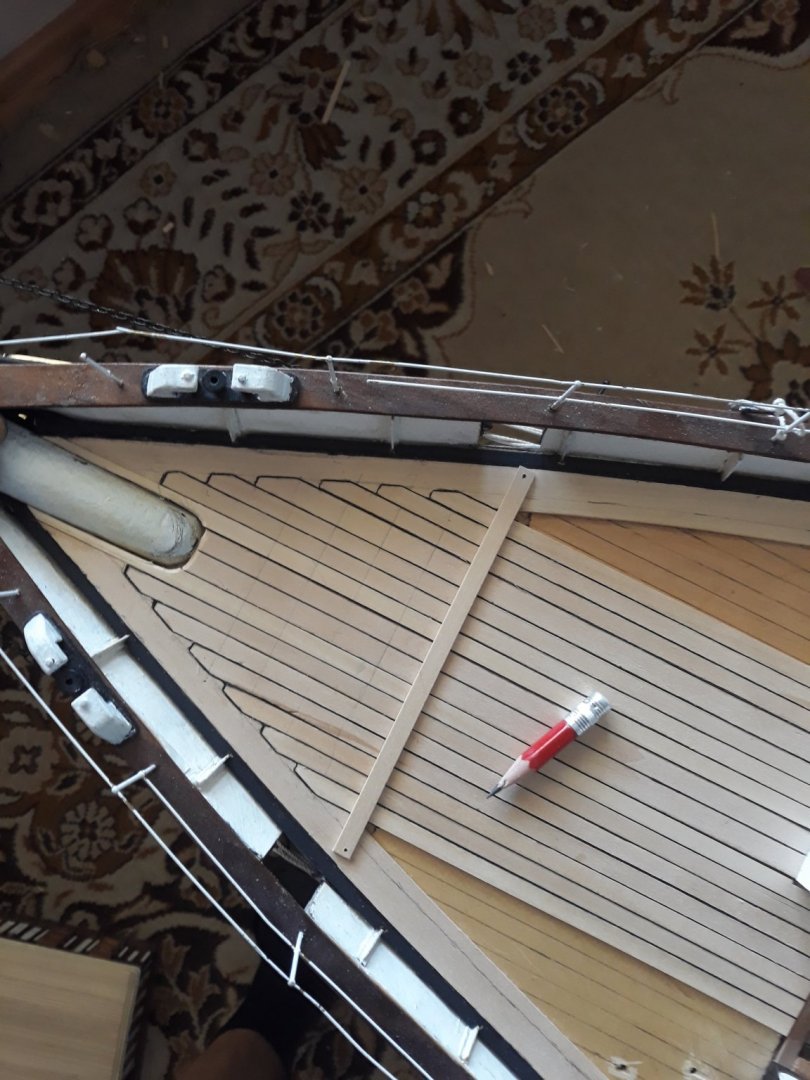
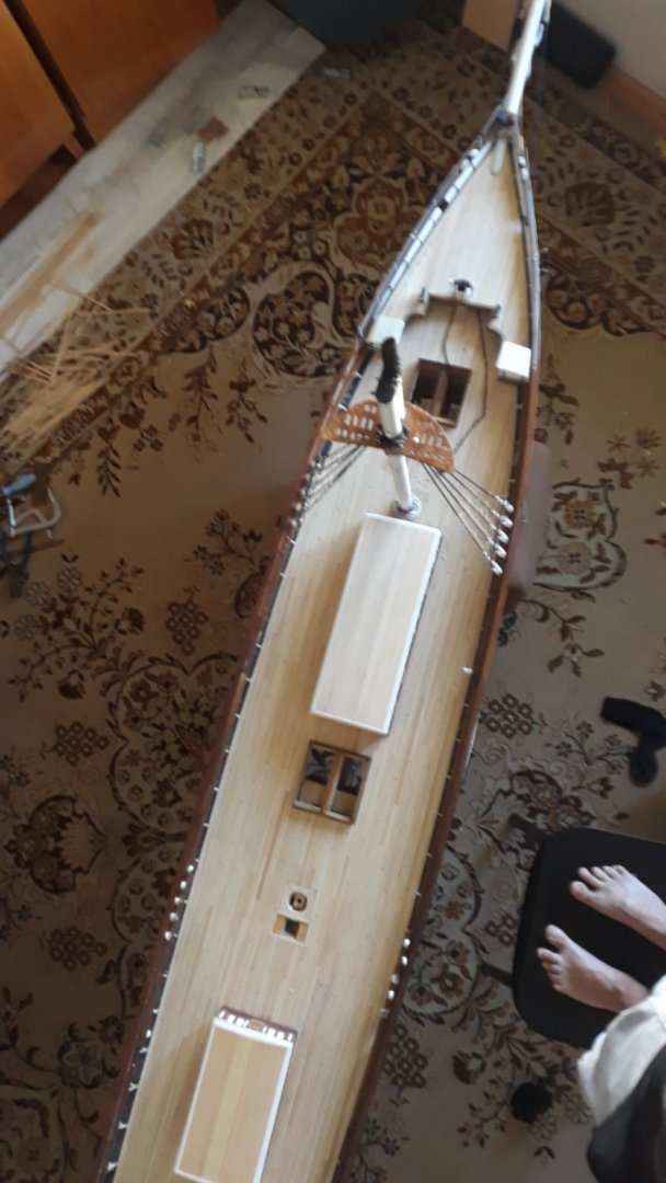
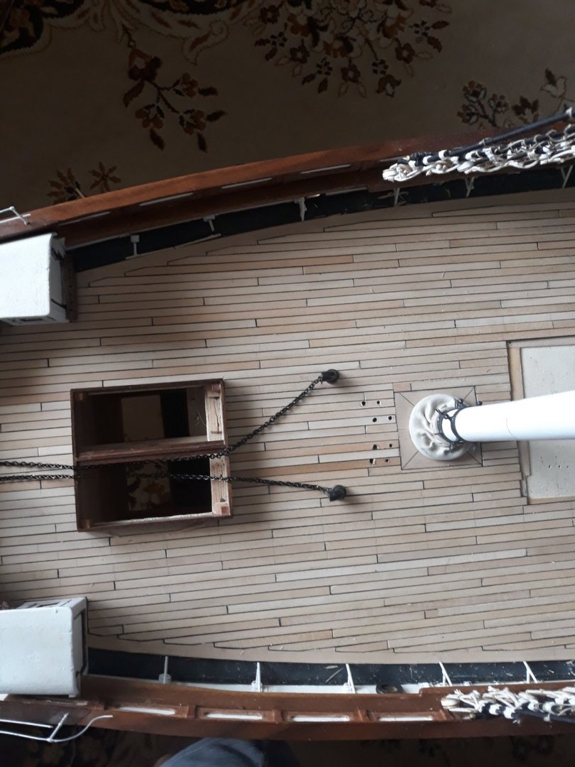
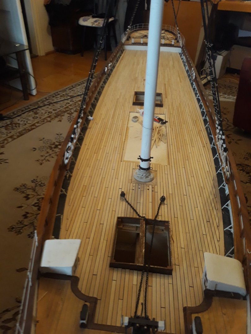
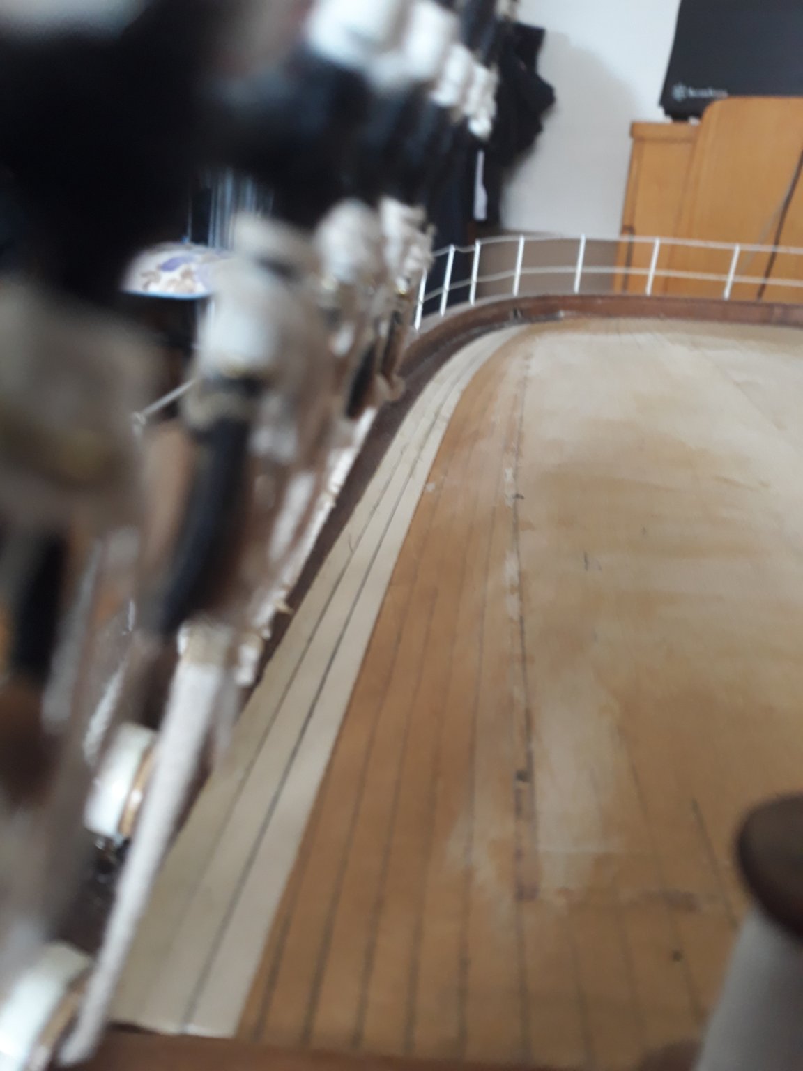
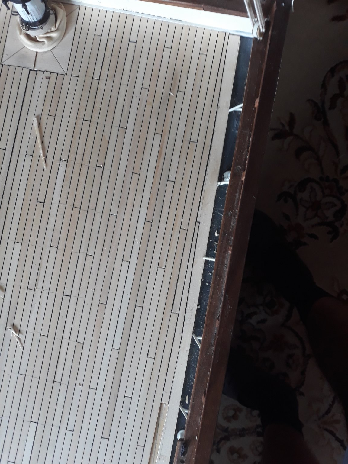
Im posting some updates from last twoo weeks. There is proper flooring completed on all decks at this point, I aimed for symetry of bibbing on forecastle deck. I installed new sheer and painted proper "cemented dark grey strake stands are moored into, i quite like what it looks like after i twisted metal sheet to prpoper topraip curvature facing outwards. ...i need to fill bowsprit / floor gap though... also showing how did i worked on forecastle from start to finish. Poop deck floor is properly curved along the gangway...and met in center/ probably not like prototype but...well...Toilets have dark paneling as seen on famous picture of cutty moored at melbourne wharf.
I see now that proper decking is probably one of most essential parts of boats designing / structural and functional object covering vast amount of space in ship. It looks majestic now..
From now on I will install functional machinery, etc....i have still work on remaining 2 rowboats ongoing, capitain gig and dinghy.
so that will come further. This time i will try to put on the floor osmo top finish that should not color the floor. Willl see the outcome. Many thanks for watch etc... V.

.thumb.jpg.0e4a0df6432327fa9c20bf323e34d7c8.jpg)


-
4 hours ago, rwiederrich said:
Man she is looking great...your corrections are doing the trick.
I worked on cutting out the first two bulkheads..1 and 2 anf
d fared them out. 1 is glued in place on the keel/stem but the rest will be left mobile so I can make adjustments and corrections. I wanted to get everything going so I could see 3D and actually make corrections or additions now as she is being built. Everything is baseline and can be modified if need be. The *beak* of hood is deliberately short so the actual member can fit over.
Moving along.
Rob
woohoo . fantastic. did you incorporate more angled less straight bow angle Rob? I will start my own somewere around winter. i need break after cutty. meanwhile i take first row seat. happy continuation.V.
-
12 minutes ago, rwiederrich said:
Yeah...her entry is still very sharp so I will be making mods to the bulkheads as I lay them up on the keel. Currently, I have to clean up the wood shop a bit(been working on telescope stuff) before I glue the bulkhead sheets to the plywood...prior to cutting. I'm gonna do this exactly like I did the Great Republic. Once laid out and glued...I'll section off the bulkheads and then cut them out. During this time I will have to plain down the maple I will be using for the keel and stem and the bow sections. I will NOT be building this like the boys over in the Young America logs....They are building their fine models in exact manner as the prototypes.
Not me...I'm a *Hack* modeler...all I'm concerned with is the end results.
So what will the scale be if I make her 40" long?
Rob
it is 1:75 Rob.
nice scale.
-
cant wait to see the keel laid out Rob ; all of a sudden Glory woudl be most build vessel
-
-
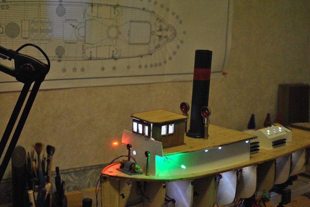
On 11/4/2017 at 9:51 AM, hof00 said:
Hi All,
A Mock-Up....
Progress? I think the "Tear Down" has been worthwhile thus far.
Looks like a bit like a Christmas Tree....

I guess this is soon the time of year.
LED installed in Deck House/Engine Room (High Intensity LED's Not Cheap!!)
Installed also in the Wheelhouse and "Navigation" lights
Mast Lights will come eventually, wiring installed.
I'll drill out the Nav' and Masthead Lights to accept the LED's
Cheers....HOF.
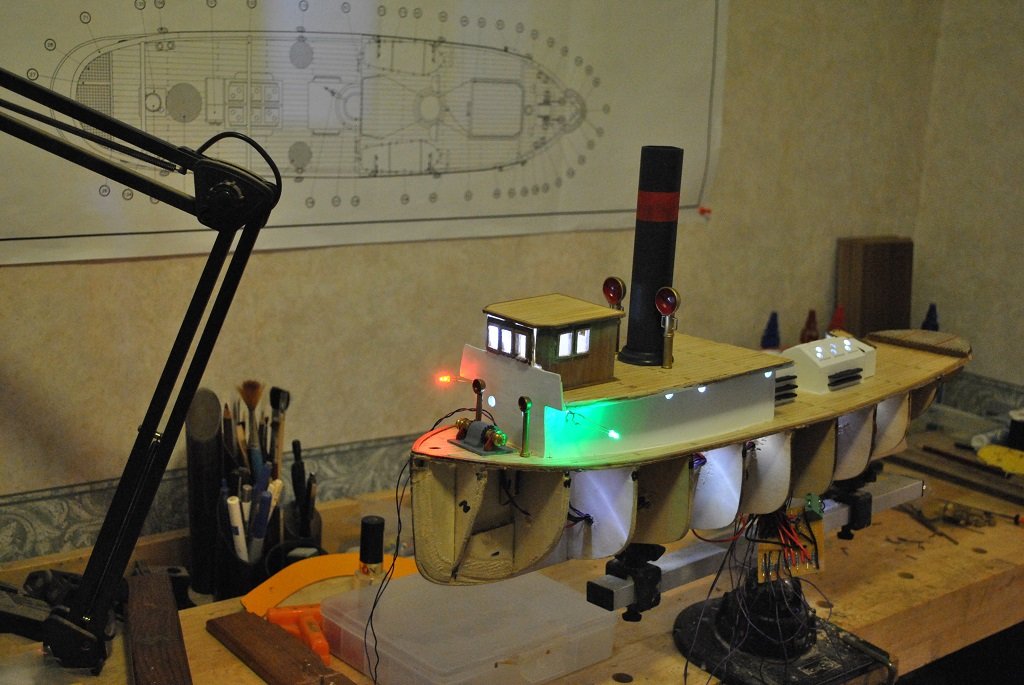
this is lovely
-
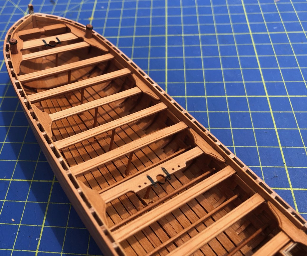
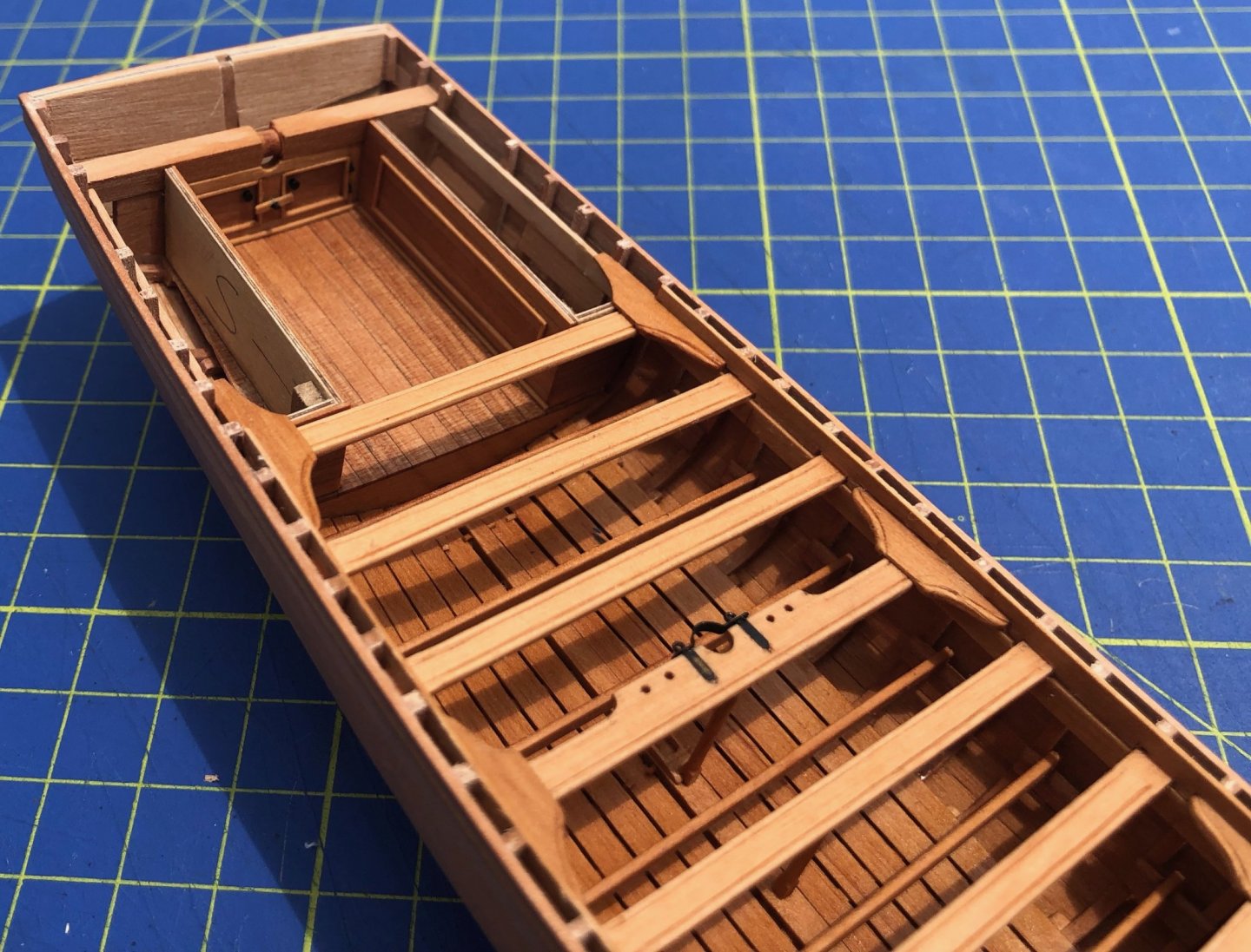
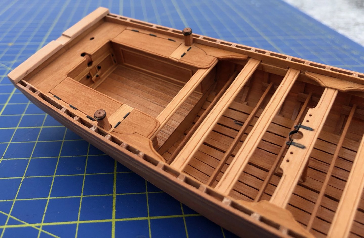
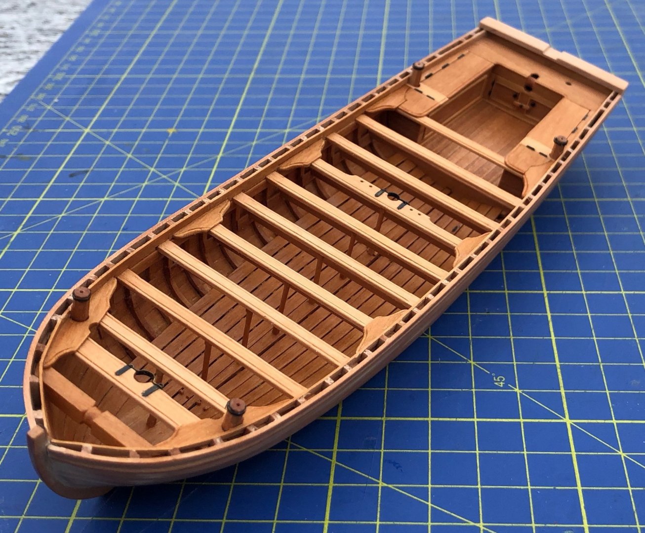
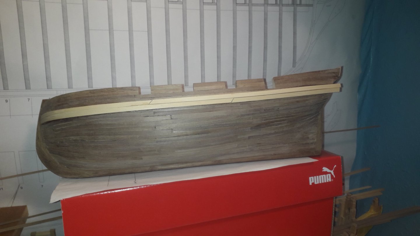
On 6/28/2020 at 11:50 PM, PJG said:
Thwart risers, some interior painting and ceiling planks:
I made one easily avoidable mistake here that careful reading of the plans and instruction book could have prevented. The thwart risers are intended to be slightly thicker than the ceiling planks that start under them but I failed to take note of this and used the same thickness of material. I’ve noticed this in several other builds so I can see that it’s an easy detail to miss. If I had realized this before installing the thwarts themselves I would have added a thin strip to fake the extra thickness. Oh well, another lesson learned. The ceiling planks went on mostly without a hitch other than having to improvise some hidden support here and there where a plank ended and the frame it was supposed to terminate on happened to be somewhere else. The great frame disaster strikes again! I added the first coat of paint before installing the ceiling planks but added some weathering later when I had a better feel for the overall color scheme.
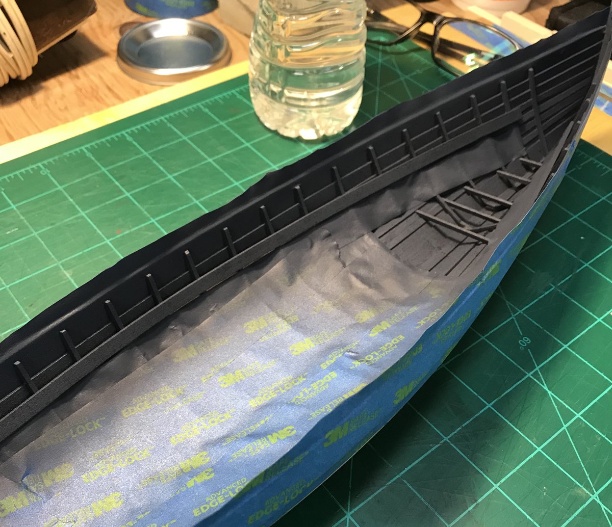
I decided to go with a dark blue/grey for the interior of the hull, thwarts and risers. These areas will be weathered to a lighter, sun-faded color eventually but my overall color scheme will be dark blue, black, various shades of grays, and white. Nobody seems to be able to pinpoint any particular combination of colors beyond the primer coats new boats were delivered with so I did my own thing. Given the jobs these boats were designed to do and the relatively short lives they were expected to do it in, I concluded that utility was probably much higher on the list than adventures on the color wheel. Distinguishing your boat from that of another ship seems to be a reasonable criteria when considering how colors were chosen.

I installed the first ceiling plank with the light gray paint I intended to use on those to get some sense of how the scheme would work. I knew everything would be toned down considerably with a little weathering so I settled on my choices.
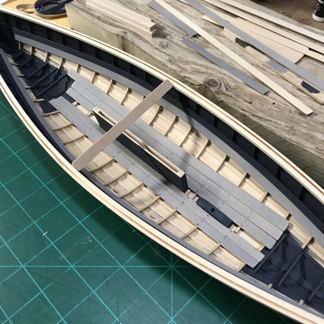
Before the ceiling planks could be installed in the bottom of the boat the centerboard case and mast step needed to be added. Painting these the dark blue rather than gray was probably something that would have been considered a waste of time in a real boat but I liked the contrast and the fact that they were installed before the ceiling on the real thing made it somewhat plausible. I didn't use fasteners on this build so I made a test of simulating nails with paint early on. I didn't think these looked overly convincing so I ended up scraping them away with a sharp blade and using a simple number 2 pencil instead. With a little weathering I thought the results were much better.
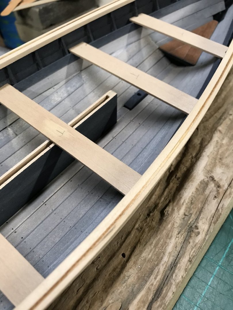
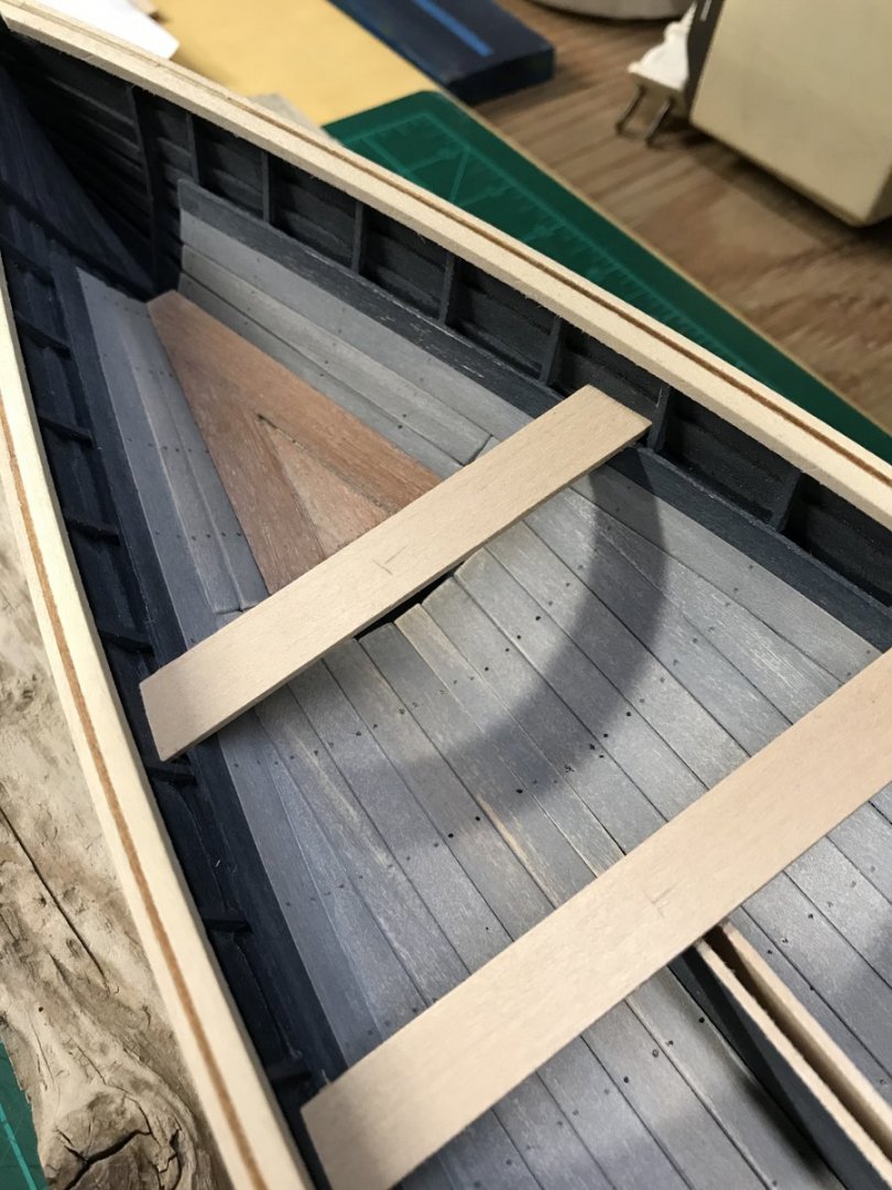
With the ceiling complete and some subtle weathering applied (in my opinion) I was satisfied to move on to test-fitting the thwarts.

With the interior mostly complete and painted, all 5 thwarts were fitted in position as per the plans. According to Ronnberg's book, the bow and stern sheets weren't painted so I resisted making them light gray. As you can see, the forward-most thwart ended up with a misplaced frame right in the middle. It should have rested between two frames. I could have moved the thwart forward and maybe gotten away with it but I decided to stick to plans from this point forward no matter what. The great frame disaster strikes again!

Fast-forward and a whole bunch of other interior details get done! All of this work took several months to complete. Carving the cheek pieces, bow chocks, loggerhead, oar locks, peak cleats and various other parts was time-consuming and educational. I thought carving was going to be my achilles heel but turned out to be something I rather enjoyed. If a particular step/activity seems intimidating, just give it a shot. You may discover you had nothing to be afraid of.
sooo fantastic build im thrilled wonderful explanation etc. i love model shipways but i onow myself how difficult is to build clinker and so on. so very detailed so realistic and nice. thanks fro sharing fantastic. i think i will try her once. oh treat for eyes .
- Tigersteve, JpR62 and BobG
-
3
-
Welcome to the cutty fanatics crowd here
happy continuation. Vlad
-
Duanelaker, im enjoying this build will follow. Vlad.
- Elijah and Duanelaker
-
2
-
-
Fingers crossed Devildog. its fine you will fugure it. definitely better to steam planks so you can bend them at critical points around stern. and there is wood filler after all so nothing to be worry about
well done. filler might be definite advantage if you want perfect hull. but nothing necessary. without it you may dill it up with file
r after done and sand to perfect shape and after paint or if you want another( thinner) layer of planks its up to you
- what helped me was always putting one plank over bulkheads to check if they lay perfectly on so they can be glued - i also sand bulkheafs dame way. with longer srick of wood with sanding paper on. so make sure sanding paper goes always thru at least 2 bulkheads and it will sand off exact amount ...:) well done. Vlad.


.jpg.fd12e2b3ace9db928ee95385309f9e63.jpg)


Providence by KenW - FINISHED - 1:48 - Colonial Sloop
in - Build logs for subjects built 1751 - 1800
Posted
Went theu log Ken, very nice work exceptional planking, inspired. following V.