BANYAN
-
Posts
5,965 -
Joined
-
Last visited
Content Type
Profiles
Forums
Gallery
Events
Everything posted by BANYAN
-
 Looks good Dave. The short tails aren't a problem. Simply tie off at the belaying point, make up some coils off the ship, then attach over the belaying point - only a close inspection with a magnifying glass or microscope would pick up the difference? cheers Pat
 -
"What a 'boring' (sorry 'drilling' ) activity you guys are caught up in . Greg, if you think your drills are having trouble with the plastic try the 3D printed Frosted High detail stuff grrrr! Looks like you are making some great progress and I am interested in seeing how this project turns out. I was just reading a little bit about her in a book that I have just completed (about Jutland) cheers Pat
-
That looks really good JCT. cheers Pat
-
Hi Rob, might be slow by your standards but you are making very good progress. cheers Pat
- 1,208 replies
-
- 2
-

-
- great republic
- clipper
- (and 1 more)
-
HMCSS Victoria 1855 by BANYAN - 1:72
BANYAN replied to BANYAN's topic in - Build logs for subjects built 1851 - 1900
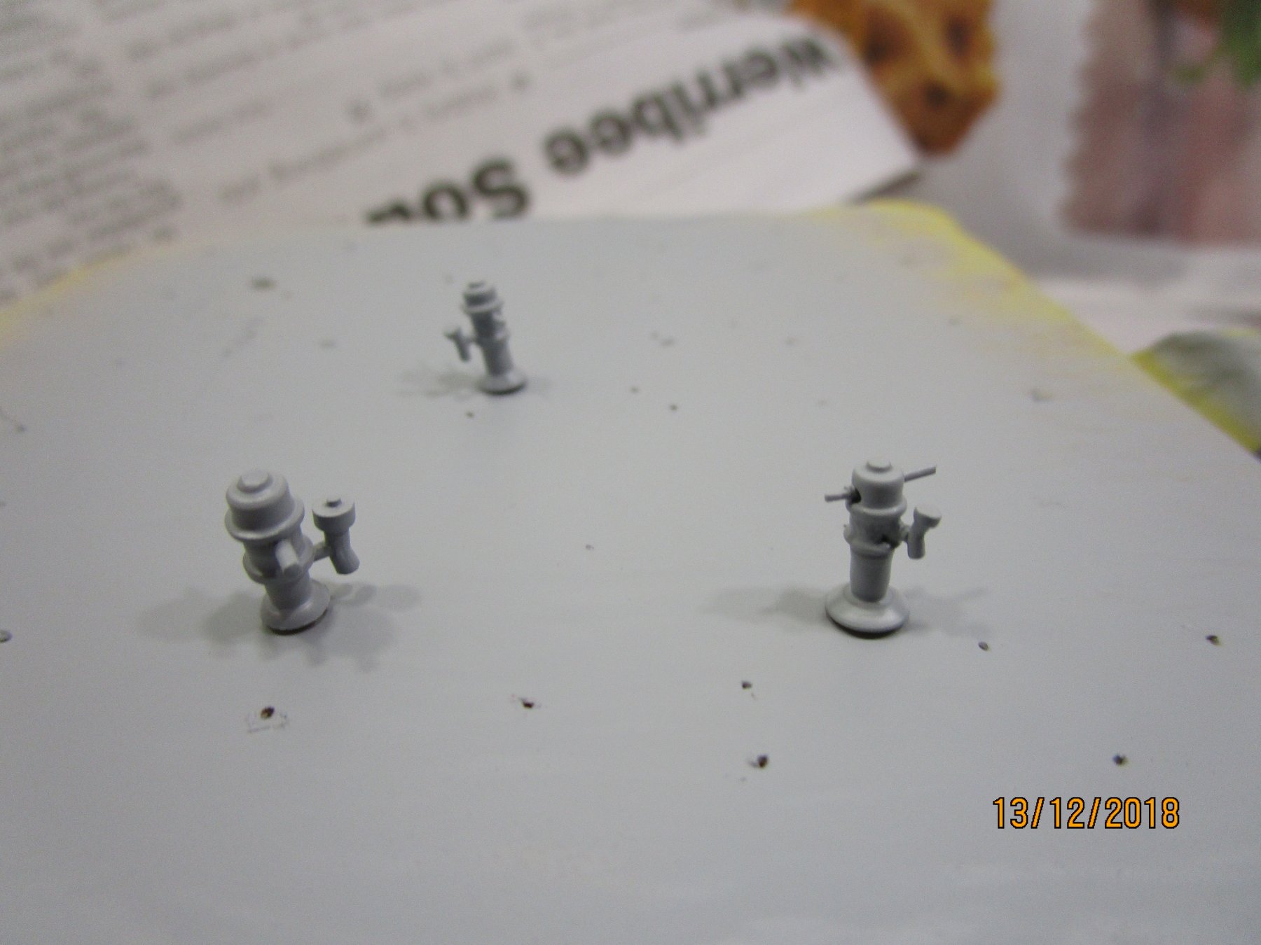
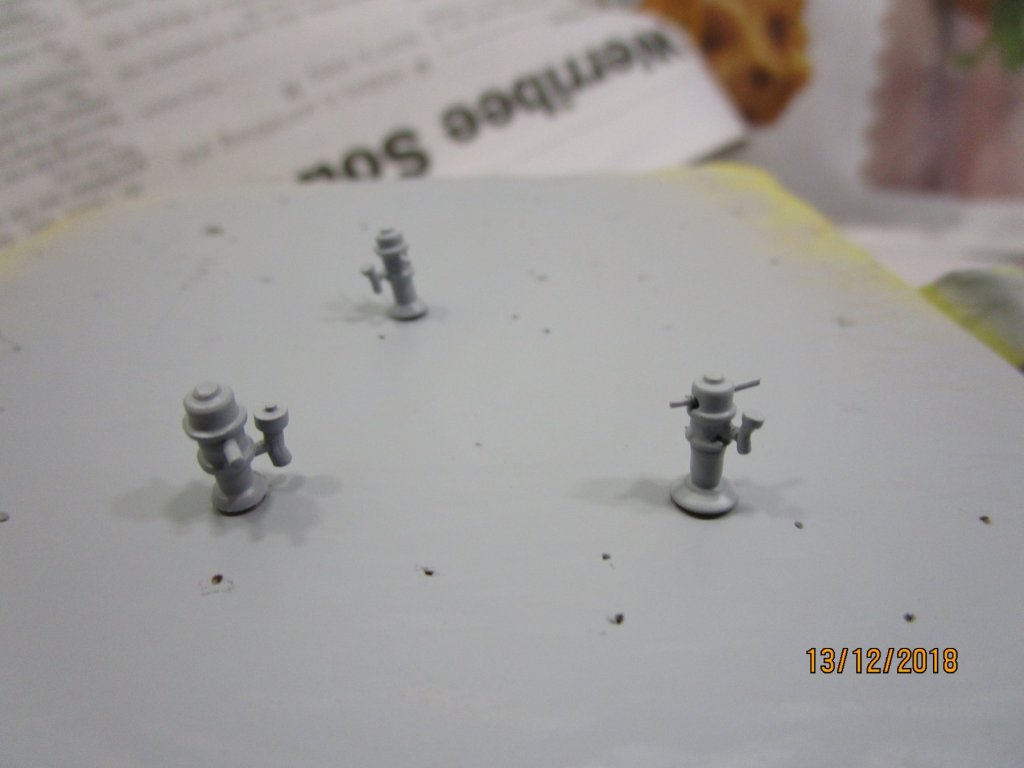
Hi again folks, Checking in with another small (and I mean small) update While it may appear not much is being done, you are right - as far as the model goes not much has been done. however, in the background a lot has been done. Most of my time has been doing the drawings for the Photo Etch parts (which should be completed this week). These include the chain plates, rigmaiden lanyards, deck winches, some fine gratings for skylights etc. I have also been busy with research getting ready to draw the plans for the spars, rigging and sails. Ed Tosti has been a great assistance in that YA has many common features and he has been most helpful. I have also been into our Public Records Office and made a great find - the actual 'Rigging Warrant' for the ship which lets me know what where wire rope, chain or natural (hemp) rope was used (sizes and lengths), where shackles and thimbles were used, the number and sizes of blocks, where rigging screws were used and also what lines etc were used with which spar etc. For example I now know the gammoning was chain and not rope etc. The research also uncovered that there were several drawings/plans (Profile, deck arrangement, midship section, sail plan, engines, boilers, 27ft gig etc) sent back, but unfortunately these may not have been kept - the search goes on however . I have also made some updates to the Downton pumps, managing to make the pump spigot smaller; this is where the 'gutta-purchase' (indian rubber) hoses would have connected. The updated ones are shown compared with the larger spigot version I had made - old one to the left obviously . The newer versions reflect the pump body shape better and shown with temporary handle axle/spindle; but I had to replace the spigot on one as the close up showed I had filed at a very oblique angle. One small detail loss in making the spigots smaller was that I could not add the squared lug on top of the upper spigot cap. The second photo shows the pumps primed ready for their white topcoat. This has been done, along with the wood base, but no photos yet. cheers Pat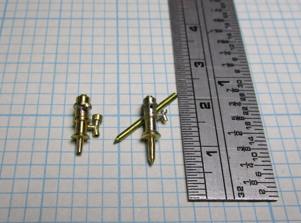
- 1,021 replies
-
- 13
-
-
- gun dispatch vessel
- victoria
- (and 2 more)
-
Nice neat work and should look great - the lads have been out and about 'swabbing' - those decks look well and truly 'holystoned' cheers Pat
- 714 replies
-
- 3
-
-
- lady nelson
- victory models
- (and 1 more)
-
Coming along very nicely Dashi, your research will pay big dividends. cheers Pat
-
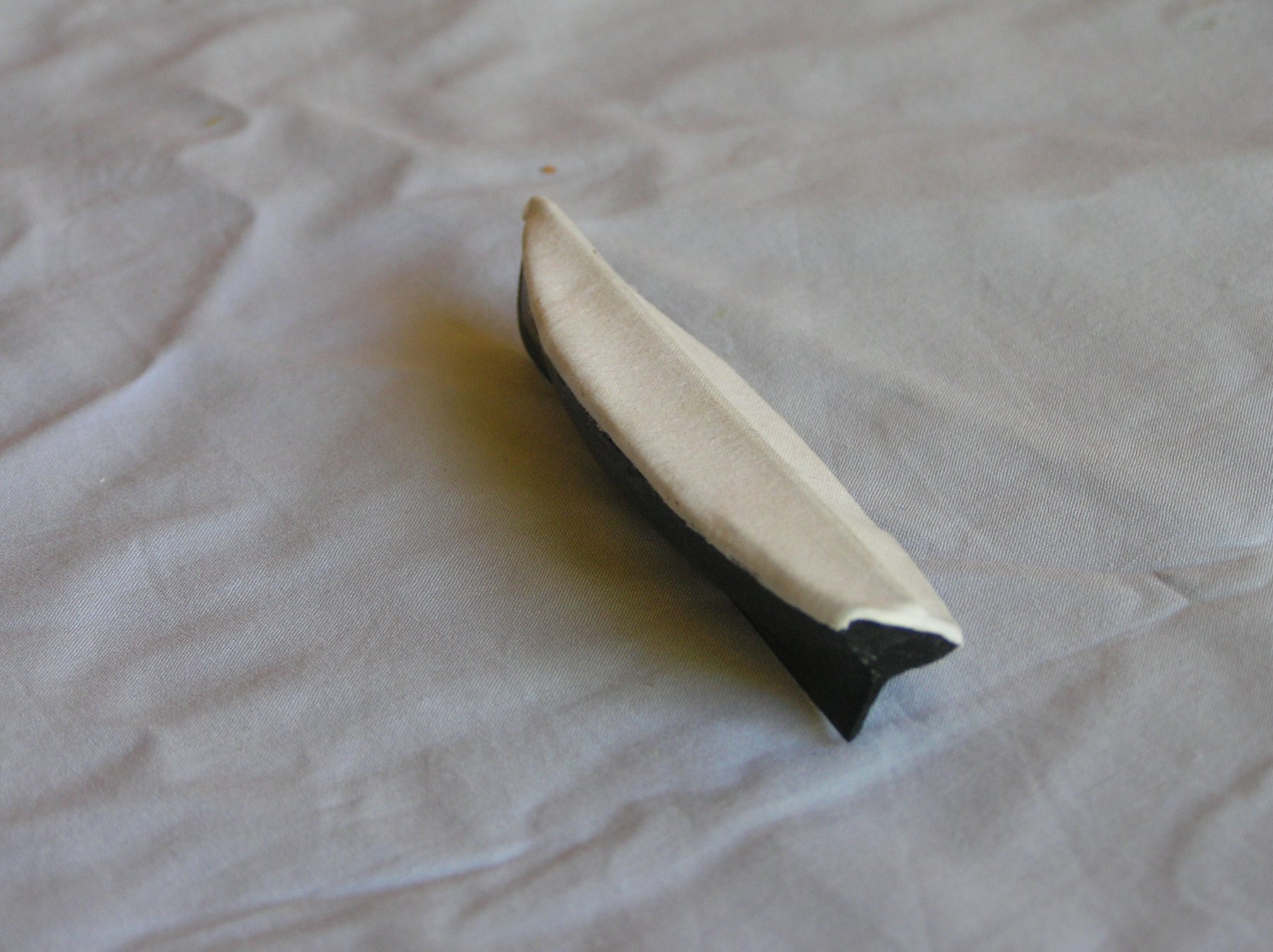
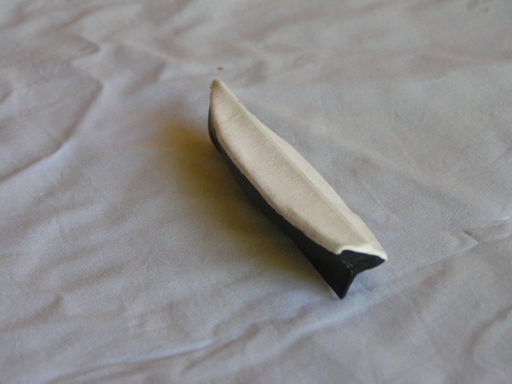
Hi Cole, I cannot speak for the merchant marine but it was general naval custom to cover all boats (sea covers) except if you were designated the 'duty safety ship' or for some evolution requiring a seaboat to be ready for immediate use, at which time the sea covers and sea lashings were removed, and 'temporary' lashings used, the boat prepped and crews on immediate call. In my time we used PVC (vinyl) rather than canvas covers, but each would have been generally formed/shaped to suit the boat. they would also, where possible have been kept as taut as possible to shed water. This latter was not always possible and we would have to go around emptying the water in the depressions etc. Attached is a photo one of the boats for HMCSS Victoria (a club build @ 1:72) showing a canvas cover. TNot a great photo but gives the general impression. Sea Lashings / gripes will be placed over these once hung from the davits. 'Victoria' was built 1855 for reference. cheers Pat
-
Thanks Vossie, I may have to adapt a mandrel to fit my 90 degree fitting as, with mine (NSK) I have the lever lock on that and the straight piece has a twist lock. Thanks for the info and links. cheers Pat
- 714 replies
-
- 1
-
-
- lady nelson
- victory models
- (and 1 more)
-
I think you chose the best option incorrecting the channels UV, looking good and the shrouds will still look 'right' cheers Pat
- 786 replies
-
- 2
-
-
- Royal Louis
- Finished
- (and 1 more)
-
Nice work Vossie; looks good. I have a micro-motor with a 90 degree attachment but it has one of those swivel clamping levers at the top; does yours have that too? If so, then I am assuming you need the specialised accessories (sanding discs etc) to suit? Again, if so, where did you get your from, my searches are restricted to a few drill/cutters and the like. cheers Pat
- 714 replies
-
- 2
-
-
- lady nelson
- victory models
- (and 1 more)
-
Hi Eberhard and Michael, as with most of us, the aging eyes do struggle at times. I have just invested (still waiting for it to arrive) in a digital microscope (battery powered and no external connections required) that has a viewing screen incorporated (and not that expensive). I am hoping to use this with a swing arm etc., and also hopeful that not having to have my eye glued to an eyepiece or distracted looking at a separate PC monitor, but rather adjacent to the work I am doing, that it will allow me to work more comfortably and with a little more precision. This is to be a Christmas pressie, so I will let you all know how it goes once I have set it up and trialled it (and after the Admiral lets me open it ). cheers Pat
-
Hi Rob, if you are adding the other stays and preventers to the other masts as you work aft, you may need to have at least one forward stay (even if not the final (position etc) to provide some resistance as you tension the others aft? I also did not do a final securing knot/bend on these until all was well settled so that I could adjust them if needed. cheers Pat
- 1,208 replies
-
- 2
-
-
- great republic
- clipper
- (and 1 more)
-
Hi Eberhard, great mini-project and the level of detail at such micro-scale will look great. Do you do your own etching? That fine mest will be something else, it will be interesting to see how that turns out. cheers Pat
-
Looking mighty fine there Rob, very realistic results with your lines. I wouldn't tidy the coils too much as, especially for often-used running rigging, these would not have been overly orderly/ship-shape anyway cheers Pat
- 1,208 replies
-
- 2
-
-
- great republic
- clipper
- (and 1 more)
-
Another fine exemplar Ed; you are really 'ploughing the road for me - much appreciated. AS stated many times by many modellers - exceptional metal smithing! cheers Pat
- 3,618 replies
-
- 2
-
-
- young america
- clipper
- (and 1 more)
-
At least you are still making progress Denis; and she is looking grand. WRT the rubber bands, it may also be that fumes, or contact with, the glue accelerated the deterioration of the bands - I replace them quite often because of this. cheers Pat
-
Hi Dashi, sorry I don't have sufficient knowledge in these things to provide a definitive response for you. However, your research results appear to be fairly categorical in the absence of the supporting evidence used by Marquardt for the AOTS. There may, or may not, have been a good reason for his choices. I would recommend an email to the Replica guys to see what they did and why also;that may assist in resolving your dilemma? I must admit, I simply followed the AOTS. I agree with your assumptions though that these smaller spars were relatively easy to replace with onboard spares with minimal shaping to adapt them for a specific purpose. When used, a suitable blank spar timber replacement could have been sourced in many of the places he visited including NZ. cheers Pat
-
Great work UV, that looks really well done. A complex task broken into smaller projects will get the job done cheers Pat
- 786 replies
-
- 2
-
-
- Royal Louis
- Finished
- (and 1 more)
-
Man that is some lovely work Rob; a joy to see. cheers Pat
- 1,208 replies
-
- 3
-
-
- great republic
- clipper
- (and 1 more)
-
Don't worry, I am sure I would earn the bosun's wrath if he were to look at my belaying (wrong pins, leads etc) There is a booklet that is provided to volunteers on the Endeavour (when sailing) that provides the rigging plan/belaying they use so that they can learn 'the ropes' - that is also very handy if you can get your hands on it. Unfortunately I have passed my copy to another builder. that said though, there are some differences with the replica as may have been the actual belay plan, as is Marquardt's interpretation - but it can't be too far wrong cheers Pat
- 108 replies
-
- 2
-
-
- endeavour
- caldercraft
- (and 1 more)
-
TLAs, FLAs etc (Three Letter Acronyms, Four Letter Acronyms ...) When we went to a particular deployment back in the early 90s, one of the first things handed over by the USN was a book of Acronyms (A4 paper, double sided and over 2 inches thick!) cheers Pat
-
Hi Rod, WRT the AOTS, the info is in the book, you just have to hunt around a bit. The main plans you need are the the Belaying Positions for Running Rigging (page 120) and Running Rigging drawing on page 102. By looking at individual lines etc on the detail drawings (pages in between) and these two you can determine where each of the running rigging lines lead and belay. For example if we take line 19 in detail drawing I1/2 (page 103), the legend informs us it is the Spritsail yard brace (the title of the legend tells us it is for the lower yard). Then if you go to the belaying plan on page 120, and find that line in the tabular listing to get the position number (item 11 in this case) then find that position on the plan and you see that it belays to a belaying pin in the foremast fiferail/crosspiece (third in from the port outer side). Not the best schema but it works, just need to find the appropriate drawings. The main purpose I use page 102 is to help identify the main running lines leads and positions. I photocopied copied the two main drawings and enlarged them considerably to make life easier. The same generally applies for standing rigging (pages 95-100) but here there is no horizant (plan) view but is fairly evident where the lines secured. I hope this helps; just holler if you need further clarification cheers Pat
- 108 replies
-
- 2
-
-
- endeavour
- caldercraft
- (and 1 more)