BANYAN
-
Posts
5,937 -
Joined
-
Last visited
Content Type
Profiles
Forums
Gallery
Events
Everything posted by BANYAN
-
 Ditto on the quality of your workmanship Alex; always a joy to see your work. cheers Pat
 -
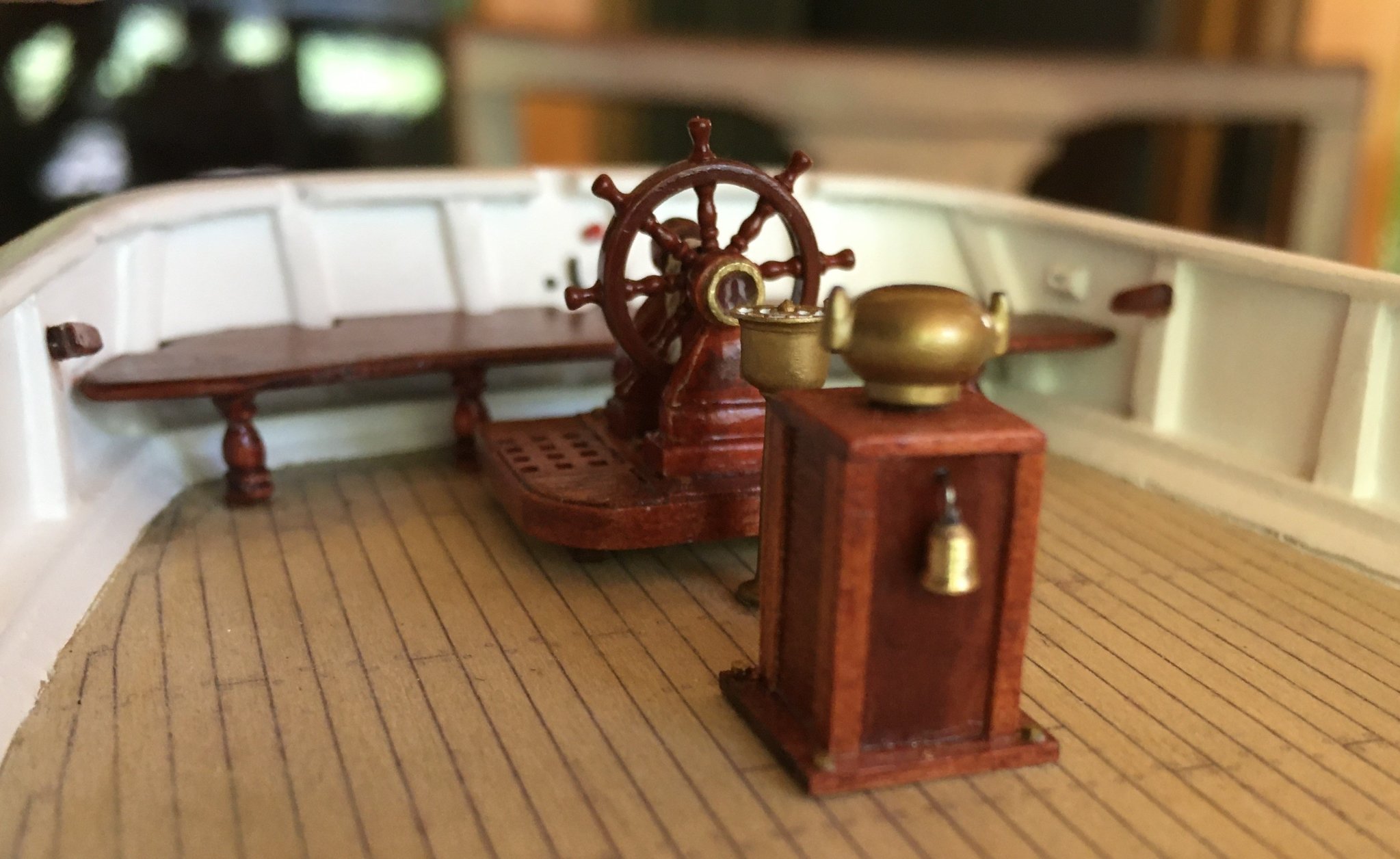
Greg, those are the 'naval pipes' (one each side) fitted with a bonnet (bent part) and a hand wheel operated guillotine (cable stopper/brake) . On deck will have been a blake slip for letting go the cable and a screw slip for use as a 'preventer' (I think I can see the screw slip on deck). The blake slip would have been fitted to engage with the cable on it forward sweep on the fore side of the capstan with the bottle screw slip further out near the hawse pipe/hole. cheers Pat
-
HMCSS Victoria 1855 by BANYAN - 1:72
BANYAN replied to BANYAN's topic in - Build logs for subjects built 1851 - 1900
Thanks for looking in and comments Keith and Rob; much appreciated. cheers Pat- 1,006 replies
-
- 2
-

-
- gun dispatch vessel
- victoria
- (and 2 more)
-
HMCSS Victoria 1855 by BANYAN - 1:72
BANYAN replied to BANYAN's topic in - Build logs for subjects built 1851 - 1900
Thanks John. In the modern day that would be the Quartermaster - I think back then also; so it is in a convenient place without getting in the way. I placed the door of the binnacle to the rear as a form of spray protection; but if flipped around, the bell would be in an even better place cheers Pat- 1,006 replies
-
- 3
-
-
- gun dispatch vessel
- victoria
- (and 2 more)
-
HMCSS Victoria 1855 by BANYAN - 1:72
BANYAN replied to BANYAN's topic in - Build logs for subjects built 1851 - 1900
Another small update; the watch bell has been added to the binnacle. This was turned by another club member; it is only a few millimetres in size (5 x 3 if I recall). This bell was called for in the Specification/Contract, in addition to the ship's bell, but only stated that it was to be in the vicinity of the helmsman. We thought this to be an appropriate place? The compass cover has not been glued down yet as we are think of making one from copper/brass. This is a white metal one that has been adapted and painted brass. cheers Pat
- 1,006 replies
-
- 11
-
-

-
- gun dispatch vessel
- victoria
- (and 2 more)
-
HMCSS Victoria 1855 by BANYAN - 1:72
BANYAN replied to BANYAN's topic in - Build logs for subjects built 1851 - 1900
Thanks all for looking in and very encouraging comments, much appreciated. Tony, yep, CNC cutting is far better than laser cutting, particularly at this scale. Laser cutting risks potential damage to the parts when cleaning the char (even if cut at low power levels). I did try laser cut parts but I was no overly enamoured with them. Eberhard, I understand your suggestions, and did try to use brass sheaves. My attempts to turn them were very unsatisfactory, but it did not even dawn on me to use PE (well, at least it is a good idea to remember if I ever need to redo them). cheers Pat- 1,006 replies
-
- 2
-
-
- gun dispatch vessel
- victoria
- (and 2 more)
-
The results speak for themselves; well worth the effort to force yourself to the workbench - nice work Keith. cheers Pat
-
There are only a handful of modellers whom produce such clean crisp work so consistently; and your work is well up there. Thanks for sharing. cheers Pat
-
Looking great Steven; if the séance work you can ask Henry directly about the rigging etc cheers Pat
- 740 replies
-
- 4
-

-
-
- Tudor
- restoration
- (and 4 more)
-
A very nice job on the hull bottoms Greg; you have this technique nailed now. cheers Pat
-
Resistance Soldering Unit
BANYAN replied to Roger Pellett's topic in Metal Work, Soldering and Metal Fittings
Hi Roger, not sure if you are aware of this info sheet from American Beauty. On seeking their advice I was forwarded this information which may help. The particular point I am tryng t emphasise is the heat point is around the point of resistance, which they reinforce using special probes. May be worth considering when making yours? I have no financial or other affiliation with the company; simply they have been very helpful and accommodating in creating a product I needed, and in how to use it properly. " The first thing is to better understand "Resistance Soldering: How it Works and What are the Benefits" as provided in this linked document. The type of thermal energy provided is based on both resistance and conduction of the converted (high amperage, low voltage) current from the power unit. The current provided is A/C so there is no + or - when attaching the handpiece or accessories to the output terminals. The resistance to current flow causes the heat and is why we incorporate the materials used in our electrodes and elements. The conduction path is intended to have as little resistance as possible and is the reason for the materials used for the handpiece and accessory components. The copper plating on the electrodes is to improve current conduction to the tip so that the heat developed is localized to the point of contact as much as possible. If you are experiencing excessive heat where the clip of the current return harness is in contact with the component or work piece the cause is resistance or poor conduction. This issue may be caused by oxidation,dirt or other contamination affecting the required current flow. Another cause might be the location of the clip or the materials it is clipped onto. As long as the materials are conductive (copper, brass etc.) the clip does not need to be as close to the intended solder joint, but if the materials are less conductive (stainless steel) the clip should be in closer proximity to the joint." Hope this helps. cheers Pat -
HMCSS Victoria 1855 by BANYAN - 1:72
BANYAN replied to BANYAN's topic in - Build logs for subjects built 1851 - 1900
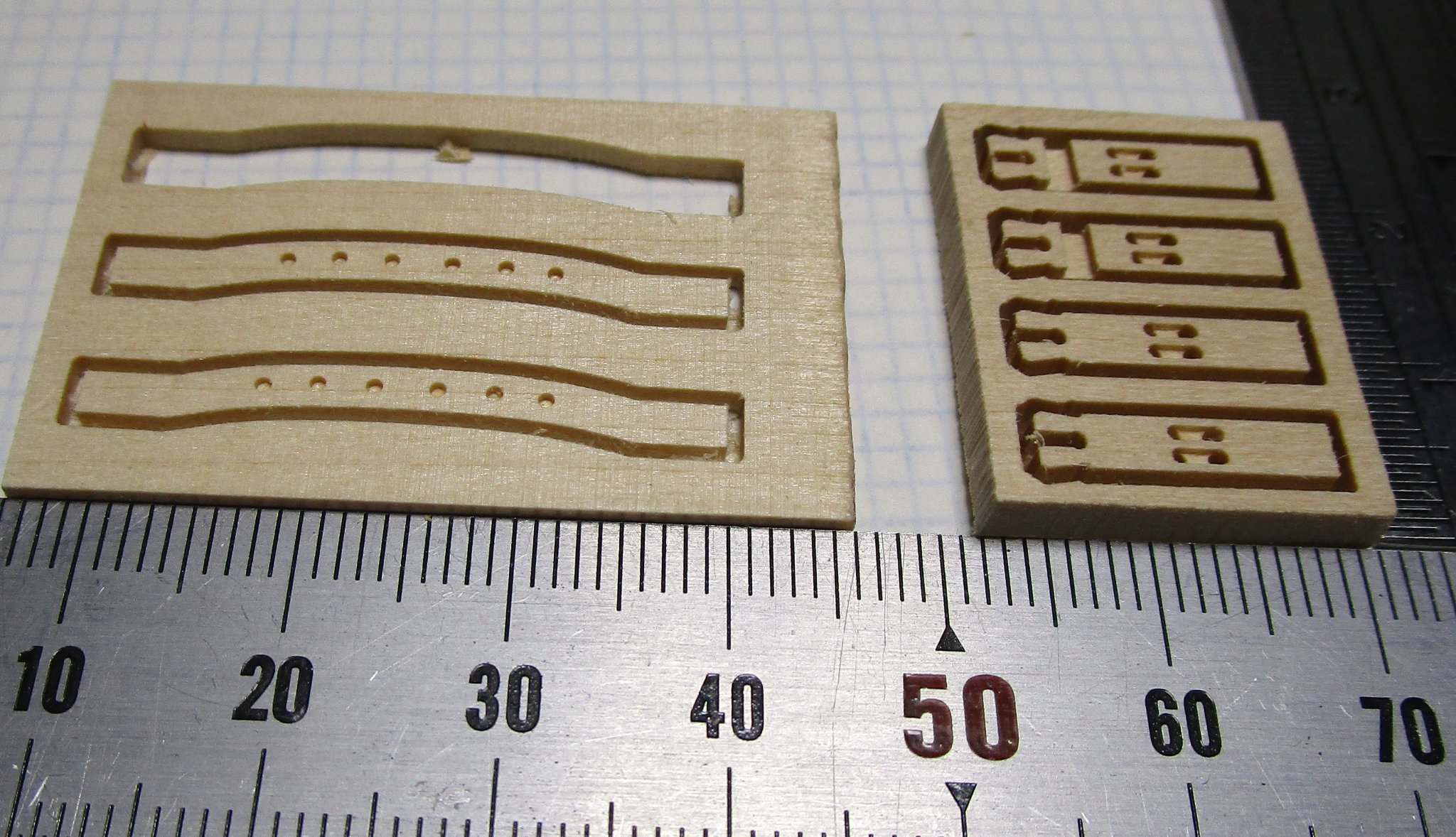
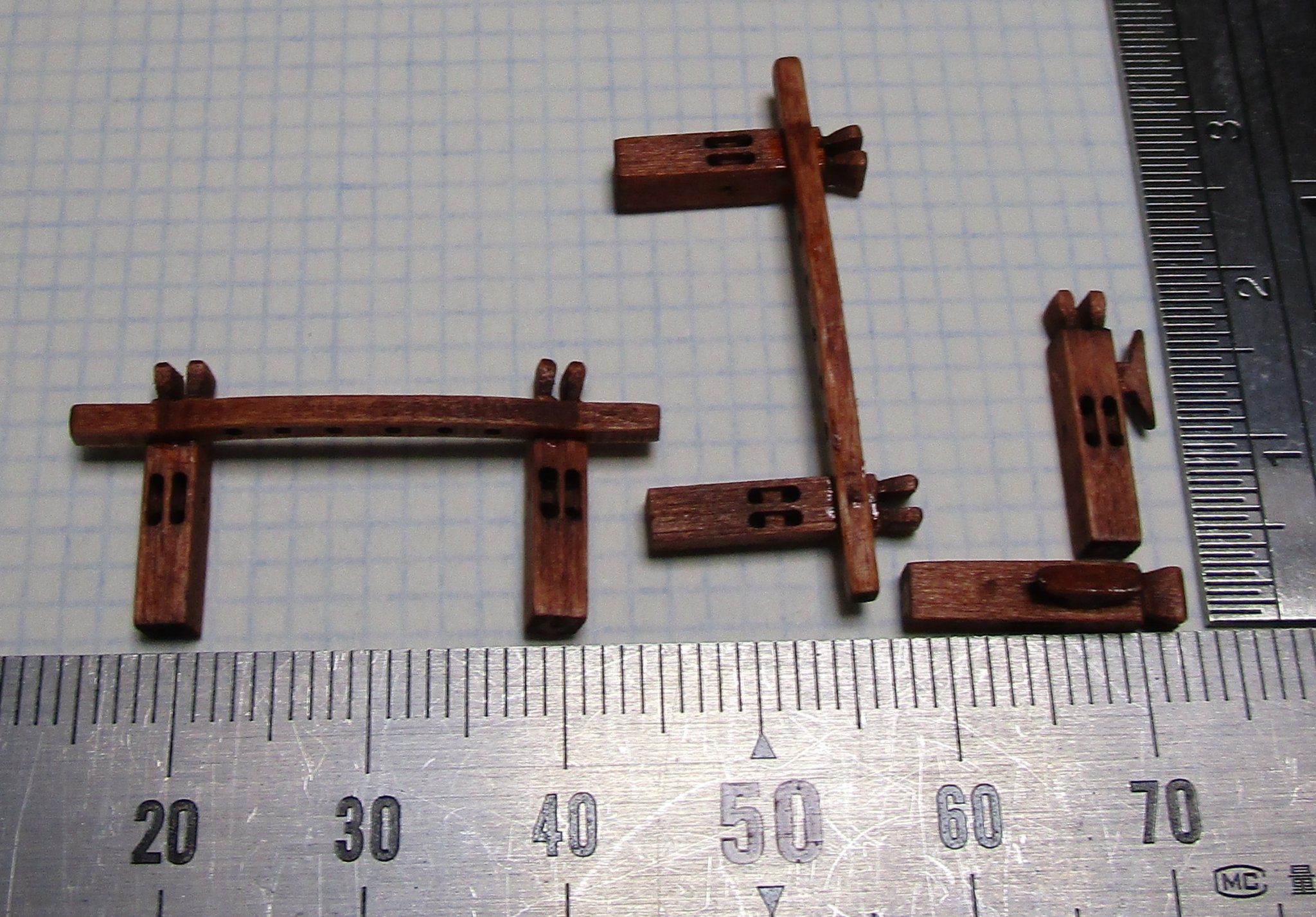
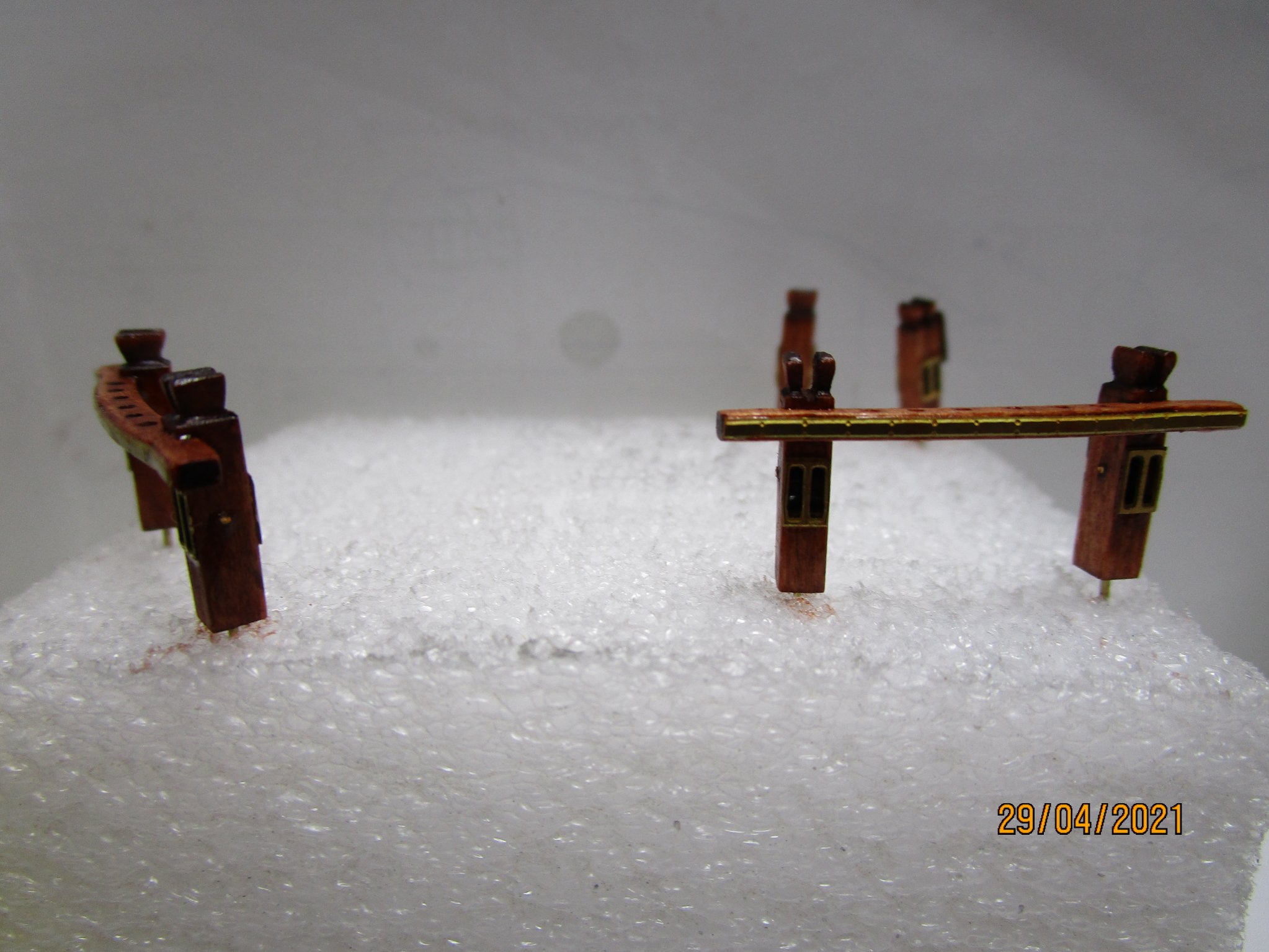
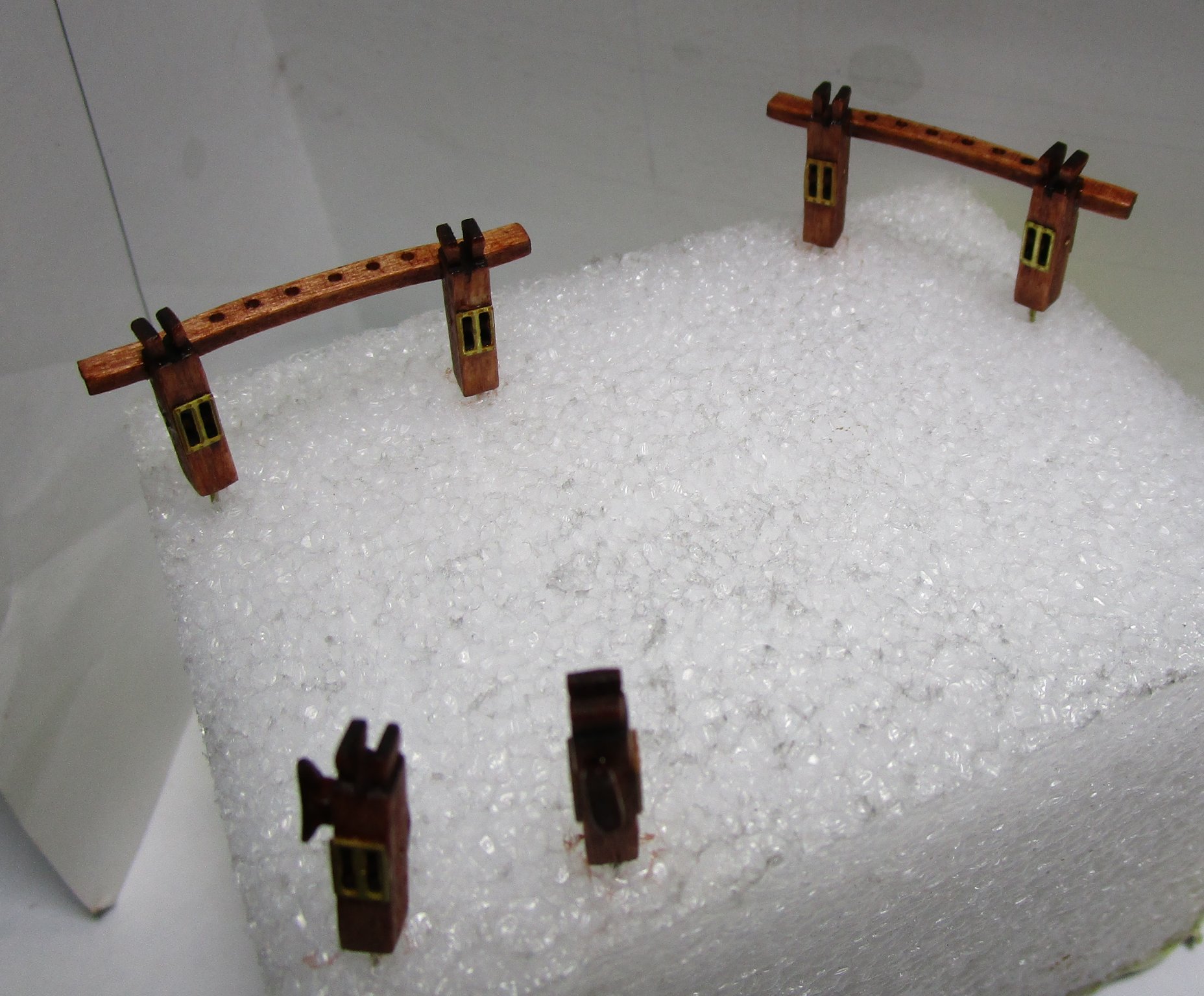
Sorry for the long delays and spasmodic posting of updates, but I have been somewhat distracted from the build by research. I am at the point I cannot progress until I finalise the rigging and belaying plans, and noting the unique rigging arrangements, this is taking a lot longer than I anticipated. Progress is good and I and in the final stages of that which has allowed me to make some small progress on the build. I have completed the lower spars and adding the fittings now. I will post some photos of them soon. In the meantime I have progressed the sheet bitts as shown below. I must thank Mike Shanks for his assistance in CNC cutting these for me. I drew up the plans for these and for the PE. Even at 0.2mm the PE looks slightly oversized, but the best I could get done locally. For reference, the brass strips along the cross-piece is only 1mm wide and I tried to simulate the screwheads (not that successful though). The single bitts are placed , one each side abaft the mizen, while the two sets with cross-pieces are placed before the fore and main masts. cheers Pat


- 1,006 replies
-
- 15
-
-
-
- gun dispatch vessel
- victoria
- (and 2 more)
-
YOUNG AMERICA 1853 by Bitao - FINISHED - 1:72
BANYAN replied to Bitao's topic in - Build logs for subjects built 1851 - 1900
A very fine example of your modelling craftsmanship, your workmanship is exemplary. cheers Pat- 257 replies
-
- 3
-
-
-
- young america
- Finished
- (and 1 more)
-
Great to see you back in the workshop Keith; I have missed your updates. Another fine example of your techniques, machining skills and execution mate, they look great. cheers Pat
-
YOUNG AMERICA 1853 by Bitao - FINISHED - 1:72
BANYAN replied to Bitao's topic in - Build logs for subjects built 1851 - 1900
Thanks Eberhard, makes more sense now. I buy a lot of their burrs and drills, so I will have a poke around their site again. cheers Pat- 257 replies
-
- 2
-
-
- young america
- Finished
- (and 1 more)
-
YOUNG AMERICA 1853 by Bitao - FINISHED - 1:72
BANYAN replied to Bitao's topic in - Build logs for subjects built 1851 - 1900
Your skills and build quality continue to amaze bitao; very much enjoy following this log. Eberhard, any chance of a photo of one of those rivet tools; I am having a hard time visualising what you describe I hope you don't mind bitao? cheers Pat- 257 replies
-
- 2
-
-
- young america
- Finished
- (and 1 more)
-
Those spars look good Keith, all starting to come together now. You just need to be a 'little' patient cheers Pat
-
I had wondered what had side tracked you Patrick; nice to see another well executed miniature for your collection. cheers Pat
-
Nice job Steven, the finish looks just like an iron casting. cheers Pat
- 740 replies
-
- 3
-
-
- Tudor
- restoration
- (and 4 more)
-
Looks good Denis, another for your collection of beauties. cheers Pat
- 1,090 replies
-
- 7
-
-
- showcase models
- vendetta
- (and 2 more)
-
I don't know how I missed this Druxey; I hope there is room for a late-comer to the party. Seeing what you achieved in other builds, this should be another beauty. I, and I am sure many others, appreciate the tutorial on how to develop a boat/building plug. cheers Pat
- 433 replies
-
- 4
-
-
- open boat
- small boat
- (and 1 more)
-
Looking mighty fine Keith, some lovely detail emerging. It reminds me I have to get back to the workbench - too much time spent researching the rig (but almost complete now). cheers Pat
-
Hopefully all will be sorted for you quickly mate; know where you are at as I have the same issue. cheers Pat