

Thukydides
-
Posts
787 -
Joined
-
Last visited
Content Type
Profiles
Forums
Gallery
Events
Posts posted by Thukydides
-
-
-
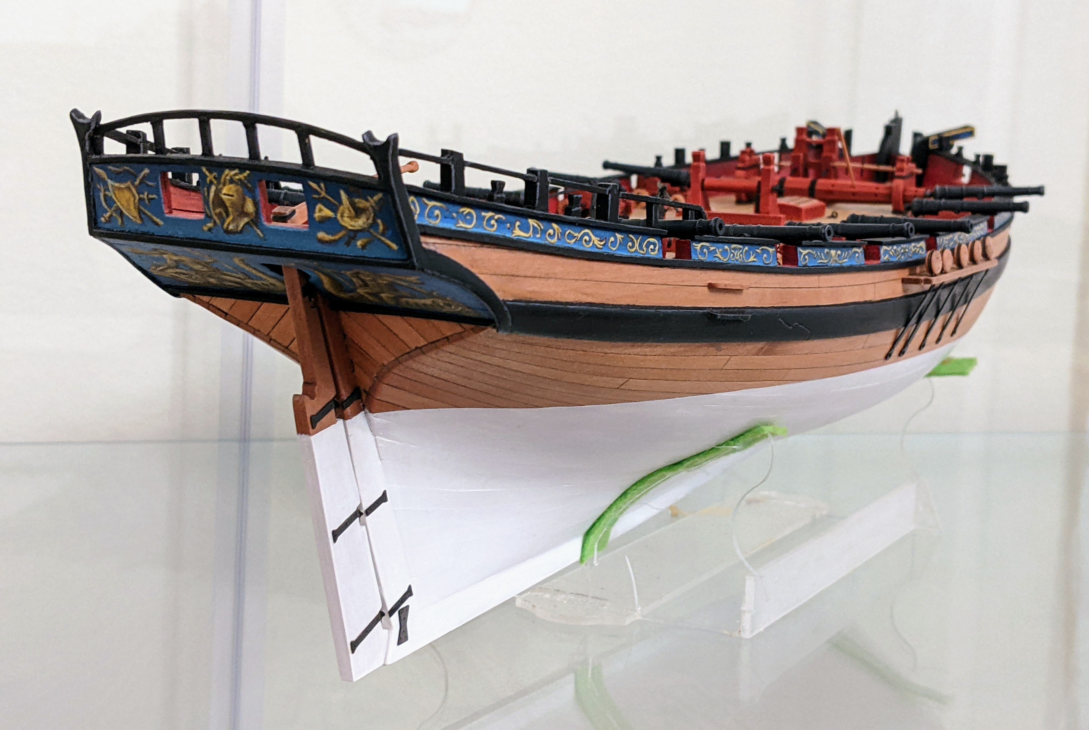
Log #19: Cutting the Gun Ports
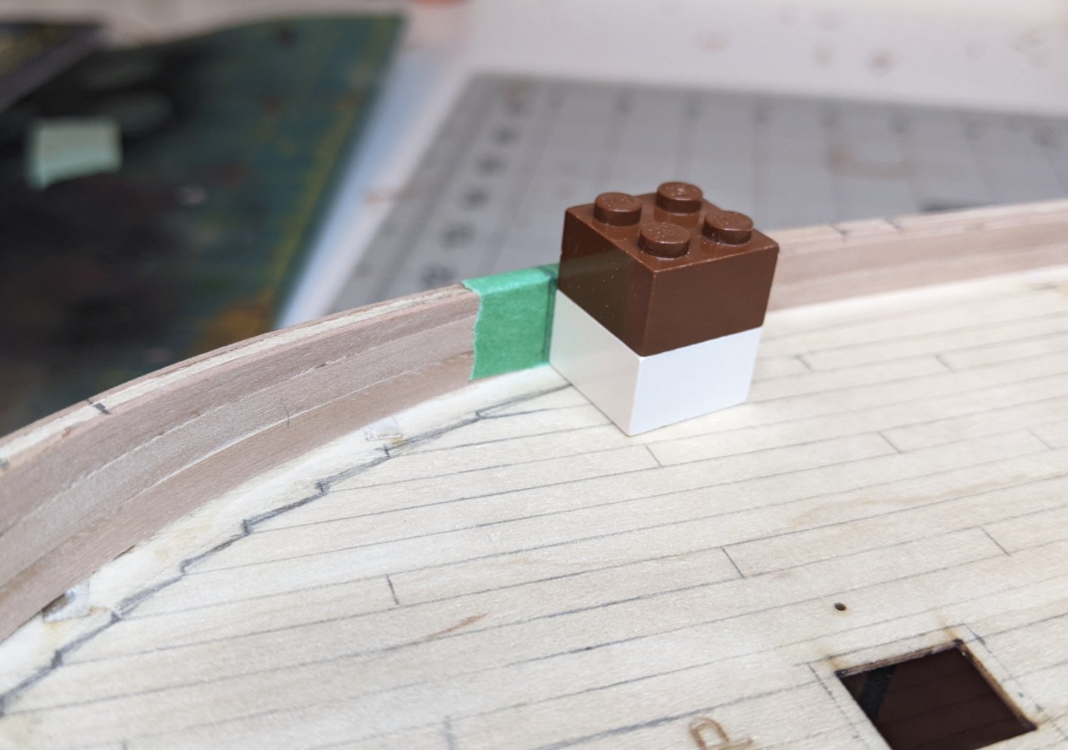
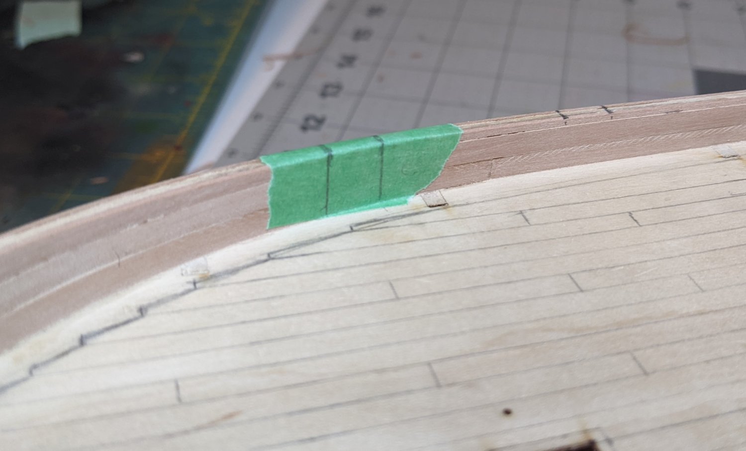
Things have continued to progress slowly. With the inner bulwarks done, it was time to cut the gun ports. Like most things I have embarked on over the course of this project, it was much harder in practice than I expected. To avoid splintering I taped the bulwark with masking tape before marking the gun ports. To ensure that the ports were cut perpendicular to the deck and in a consistent manner I used lego blocks.
After marking out the location using the railing as indicated in the instructions, I used the lego to draw the two parallel cuts.
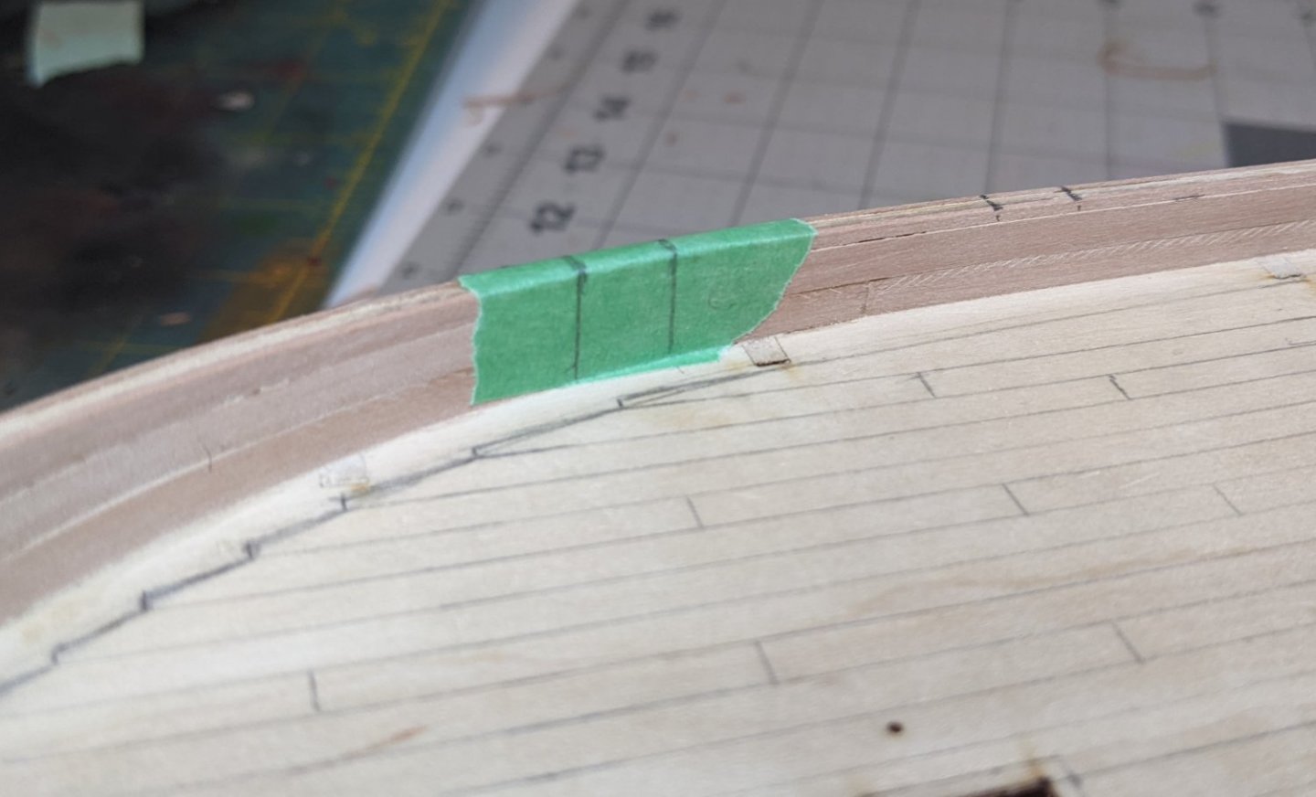
Then using a razor saw and the lego clamped against the bulwark as a guide I made the cuts down to the required height. I found that making the cuts was easy to get wrong. On a few of the ports I made the cuts at a slight wrong angle or slightly two far apart. On two of these the additional width was noticeable and I had to add back some additional material.
I then filed the edges to conform to the bulwark. In the end where this will be painted it shouldn’t be too visible. Finally I filled in any gaps with some wood filler.

-
-
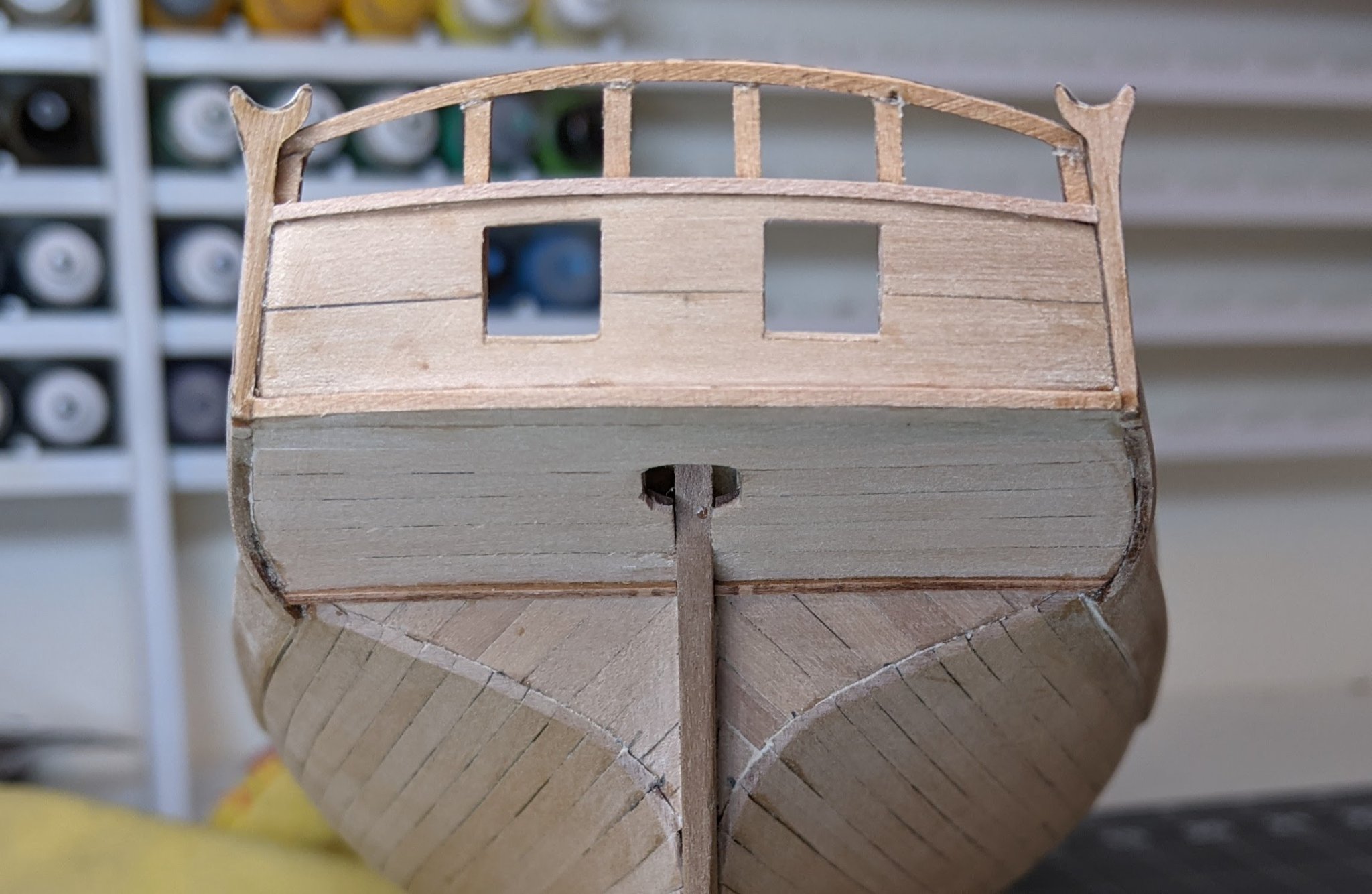
Log #18: The Inner Bulwarks and Fixing the Boom Crutches
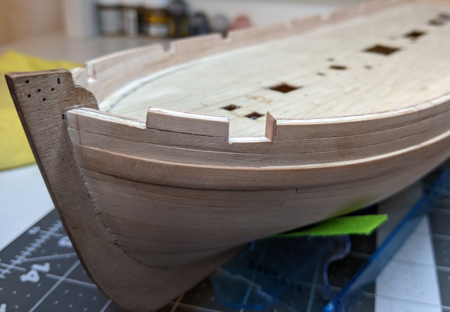
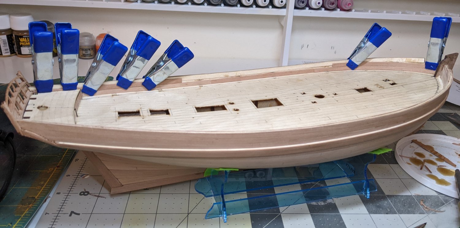
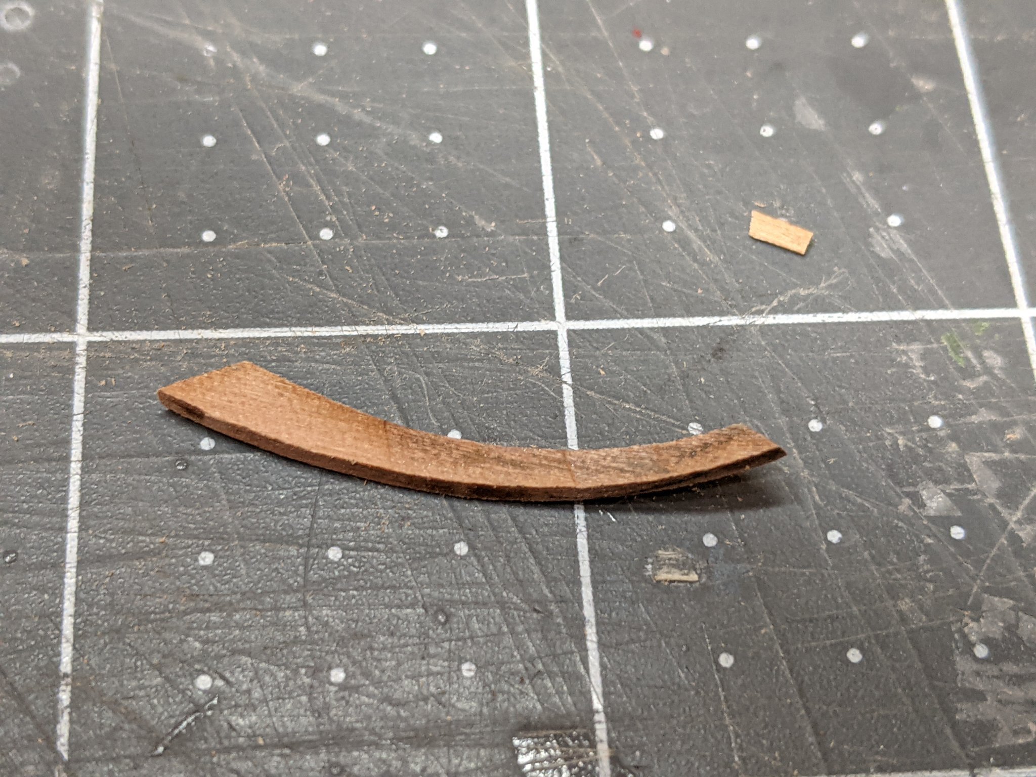
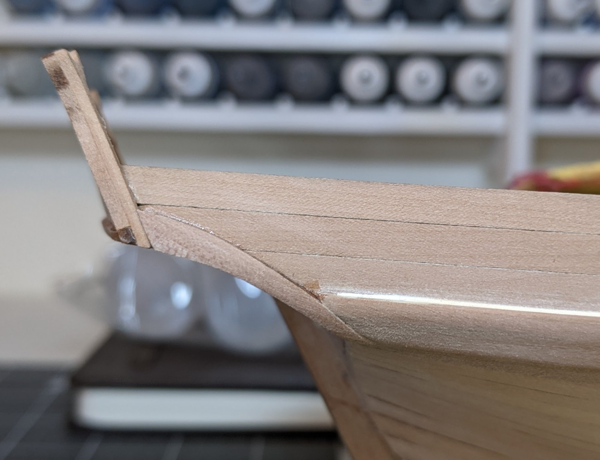
As @Blue Ensign managed to catch, the boom crutches were turned a little outward following the run of the hull instead of inward. This is a great example to me of what a valuable resource this forum is. I had always just assumed these were purely ornamental, but now that it has been pointed out to me, the use for the crutches seems obvious.
Fortunately I had made them pretty thick and so with some careful filing I was able to remove some material to make them turn slightly inwards. You can see how much I had to adjust the angle in the picture below. Since I made them by gluing two pieces of pear together, the original line between the two pieces is still visible. They are still not perfect, but much closer to what they should be.
Next I turned my attention to the inner bulwarks. After much consideration I decided to adopt the approach of @jpalmer1970 and do the bulwarks before attaching the margin planks. That way I can much more easily get in there with my airbrush to paint and avoid the need for a bunch of precise masking.
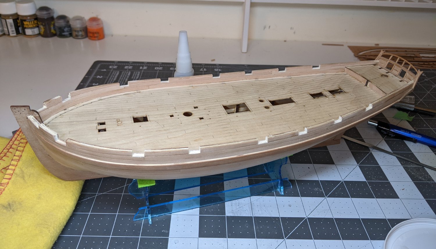
The process of planking the inner bulwarks was much the same as the outside. I planked the two ends and then fitted the middle plank. The only complicated part was the shaping of the plank that ran up to the transom. Some precise cutting was required to make it fit on top of the beam I placed at the base of the transom.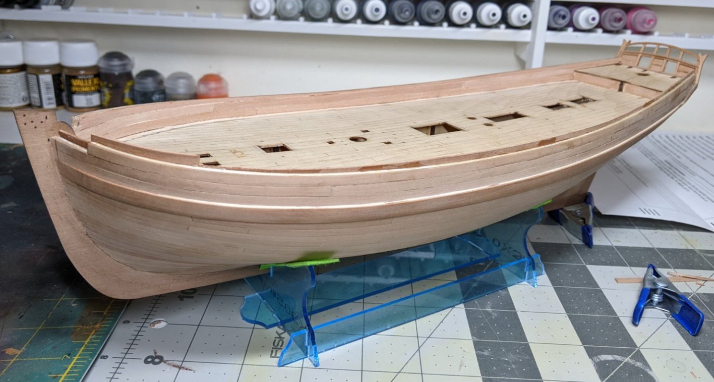
I planked without any tapering (though some slight edge ending was required). The uppermost planks then stuck up over the top of the Bulwarks (as seen in the near bulwark in the above picture). Since gun ports will be cut all the way through the upper plank, I just planked it as one big plank from bow to stern. Once the glue had fully dried I simply came back with my knife to cut off the excess material. You can see the final effect on the far bulwark.Next up, more sanding and cutting the gun ports.
- Peanut6, Ryland Craze, PhillH and 7 others
-
 10
10
-
5 hours ago, desalgu said:
I got the small dome painted and it took all of 2-3 seconds to spray. I'm sure I could have done that even when cold.
I find the biggest problem with my airbrush is the set up and cleanup time. I would use it more if I didn’t have to clean it after I was done.
-
On 1/7/2022 at 6:41 PM, desalgu said:
It's been cold here, like 10 deg-F or lower, which is too cold for me to airbrush in garage, so I tried brushing metallic paint. I've never had much luck doing that, and this was no exception. I've done 3-4 coats and brush marks still show. It's supposed to warm up tomorrow enough to try airbrushing, so hoping that will solve the problem.
If you are using a small hobby/makeup airbrush you can do it inside provided you have a big open space. When I airbrush I set up in the kitchen/dining room. I just do it at night after all the kids are in bed and cover the whole dinning tale with a cheap dollar store table cloth. It doesn't produce much paint so as long as you are wearing a respirator while painting, the room is large and you house has an air exchanger vent in the room you should be good.
-
53 minutes ago, Blue Ensign said:
Sorry to confuse,
The cut of the recess of the crutches should be angled slightly inboard so that the boom rests in them when moved across from the central line of the mast.
B.E
Ah now I understand. No I did not check this and when I went back to look, infact I have them angled slightly outwards due to the run of the hull.
I think I can somewhat correct this through some careful filing so that at the very least it is not noticable. Thanks for the tip. This is exactly the sort of thing that would never have occured to me, but now that you say it, it seems obvious 😃.
- Obormotov and jpalmer1970
-
2
-
It looks fantastic, great job!
- Saburo, JpR62 and FriedClams
-
3
-
1 hour ago, jpalmer1970 said:
Hi,
I planked the whole bulwarks and then butted the margin plank up against them. I was able to bend a couple of the boxwood strips to use as the margin planks.
That looks fantastic @jpalmer1970. Maybe my problem with the bending was I was using a wider stock because I was thinking I needed it to go under the inner bulworks.
-
24 minutes ago, Blue Ensign said:
Great start to the deck planking. 👍
I can't quite tell from the photos did you check the angles for the boom crutches atop the counter timbers?
B.E
Not sure what you mean exactly by check the angles.
-
It is up to you, but I don't think you will be able to get a good result with that as a base, the gaps and warping is too much to fix with filler and sanding. If it was me I would take off the planking and order some more limewood strips to start the first planking over.
If you are unwilling to do that you could try just removing those first two planks (which are the most problematic) and try to replace them. Not sure how well that would work...
-
On 1/1/2022 at 1:41 AM, Dave_E said:
Got 2 more planks on today… figured out I had to bend the wood the other way at the bow. If I better the 3rd plank yet some more, I’ll be happy. Every one is a challenge to get it as correct as possible.
That first plank doesn't look like it is sitting right. If I was you I would remove the planks, check your fairing again and then try again. Problems with the first few planks have a way of multiplying your issues the further down the hull you get.
I say this as someone who had to rip off the first planks and start over myself :).
Edit: what @allanyed said
")
- LyleK1, Keith Black and VTHokiEE
-
3
-
5 hours ago, jpalmer1970 said:
Hi Thukydides,
Great painting! I planked the inner bulwarks and painted them before installing my margin planks. The bulwarks may need a bit of a paint touch up when the deck is finally finished but that will hopefully be easier than painting the whole lot later. I am also considering adding a line of spirketting too if I can source some suitable wood.
So did you leave a gap at the bottom of your bulwarks to slide the margin plank into or did you just butt the margin plank up against the bulwarks?
Also how did you handle the planking of the inner bulwarks, are you able to share a picture of them?
-
Log #17: The Margin Planks
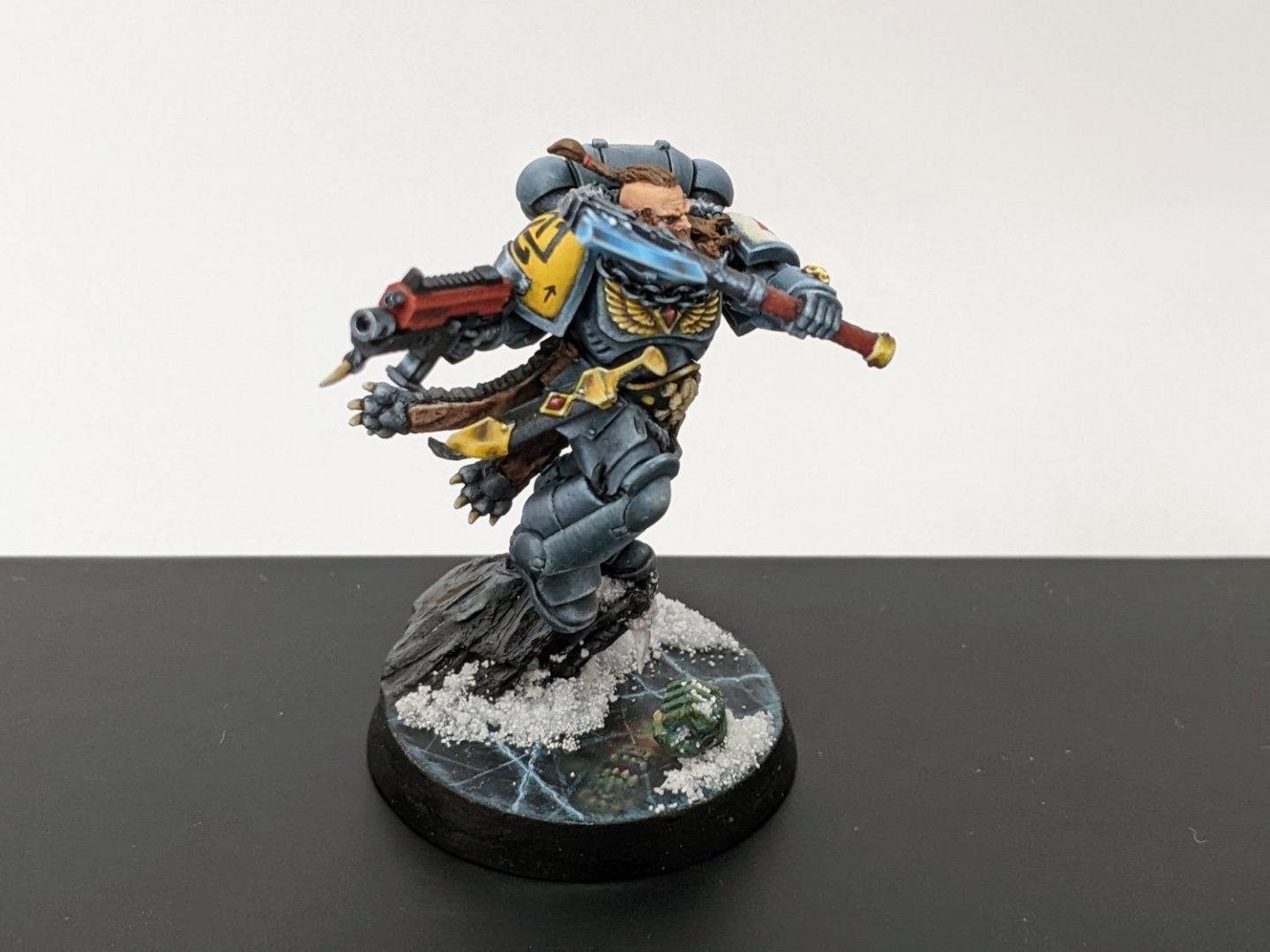
My break was a bit longer than planned due to the other projects taking longer than I expected (I ended up painting a figure for a competition so was at it for over a month), other responsibilities and then finally Christmas.
But now back to the Alert.
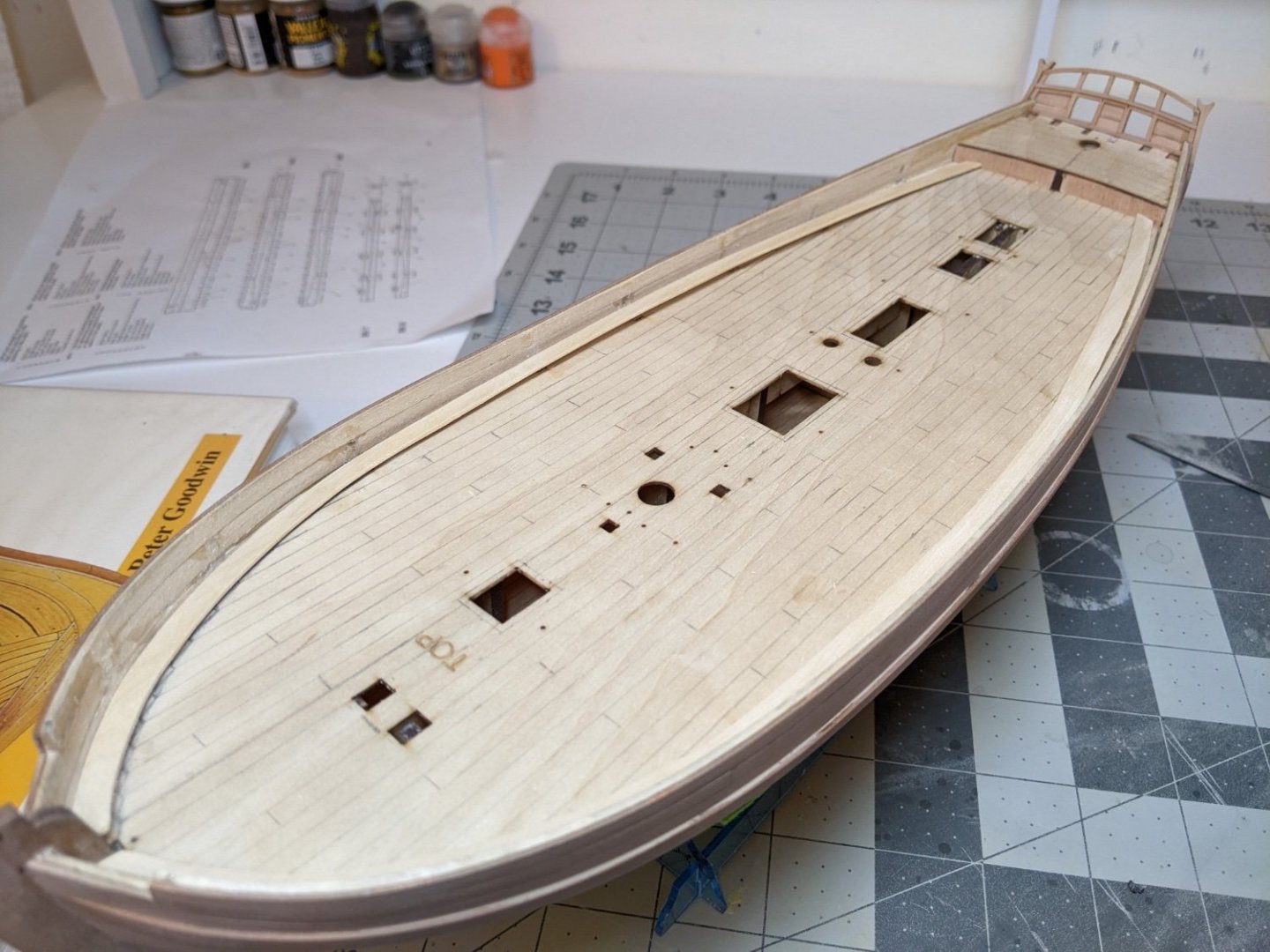
I have been struggling with how to plank the inner hull, as there are not many good angles of this in the build logs I have been reading or the instructions. I want to avoid any planks ending in a point so I guess I need to taper them. Any suggestions here would be appreciated.
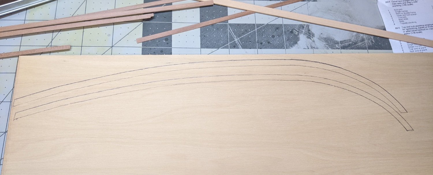
In the meantime I decided to defer the question while I worked on the margin planks. To make them I used a piece of boxwood sheet I had and used the template of the false deck to mark the outer edge of the curve. I then used a compass to mark an equal distance from that edge.

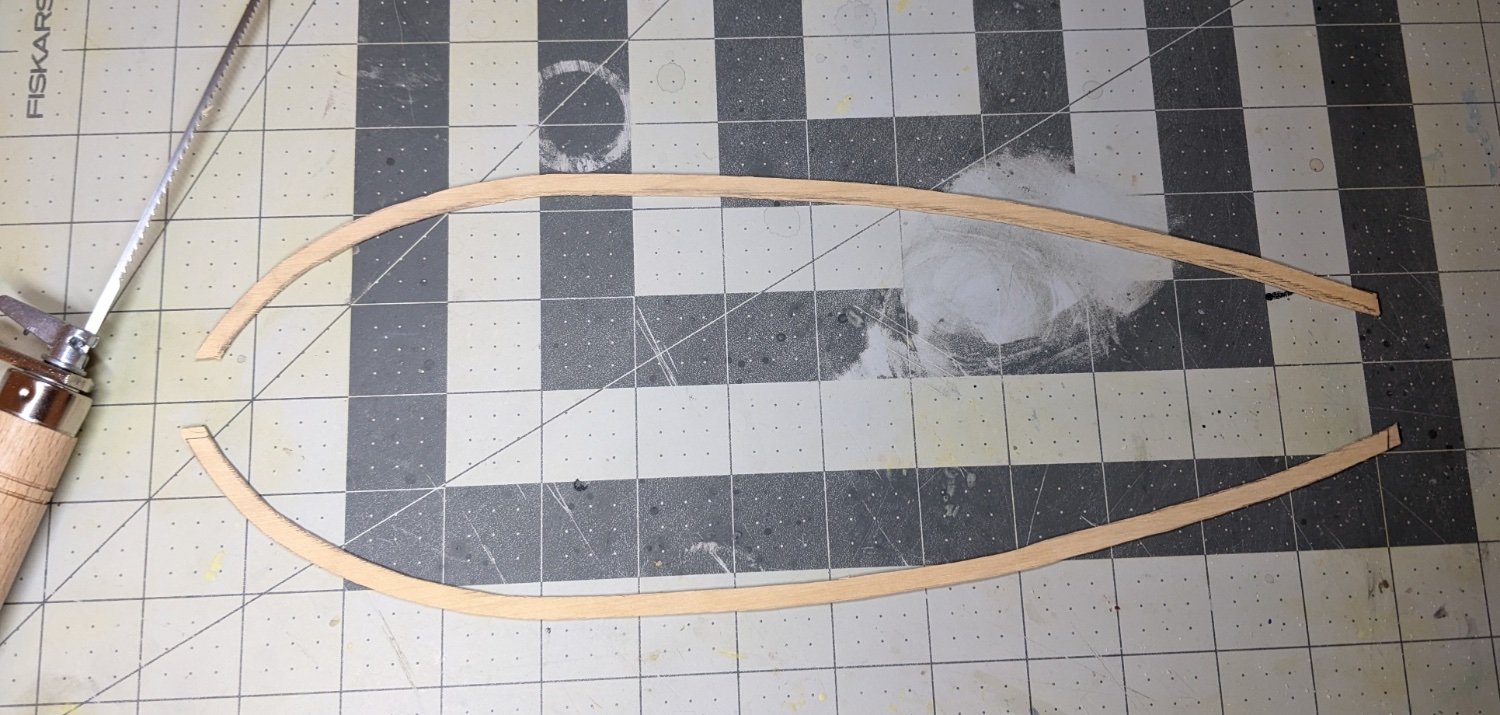
I then cut them out using a coping saw. This was much harder in practice than I had anticipated. Because of the significant bend needed at the bow, part of the margin planks end up with cross grain. I ended up breaking them by mistake twice, though fortunately I was able to get two useable ones.

I did also try bending a straight boxwood plank after I broke the first two, but the necessary bend at the bow was two extreme for me to manage even using my wife’s clothes steamer.
I am of two minds whether I should glue them in place before planking the inner hull. On the one hand being able to remove them would make the painting easier, but on the other hand the fit will probably be better if I glue them in place first. Any suggestions here would be welcome.
-
Fantastic work. I have enjoyed following along as you built this. Congratulations.
- Louie da fly, Keith Black and mtaylor
-
2
-
 1
1
-
That looks fantastic BE. Your hard work has really paid off.
-
-
Congrats on completing your build. It looks great!!!
-
5 hours ago, tomebe said:
Just finished and got up to date on your build log. Just a fantastic build of HMS alert, which I've started as well. Thukeydides thanks so much for sharing all this great info with us. So useful for a newbie like myself.
Tom
I am glad you are enjoying it. You should also start a build log :).
-
If you have an airbrush you could also paint them first black and then spray from above with a dark grey. This will simulate the light falling on them and will make the recesses stand out more. You can replicate this effect using a brush by painting black first and then dry brushing with the dark grey.
- mtaylor, CaptnBirdseye and Blue Ensign
-
3
-
-
I really like this one. It looks like it will be a great introductory kit.
-
-
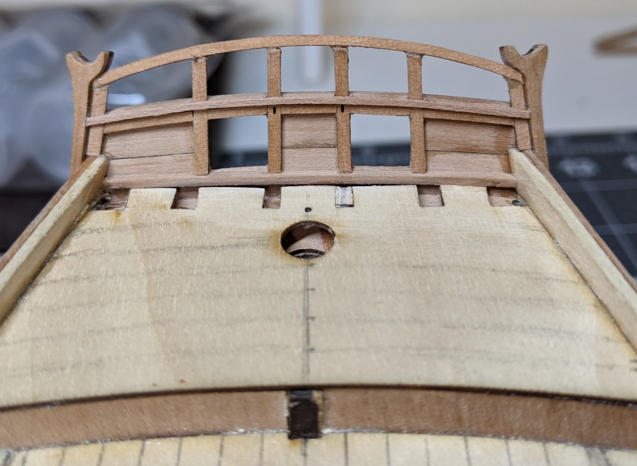
Log #16: Building the Transom Part III
In this final log on the construction of the transom I worked on the side counter timbers and the tafferal.
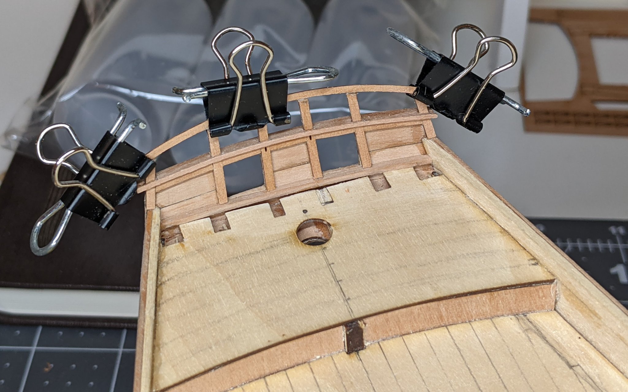
The tafferal was one of those things that in theory seemed simple, but in practice gave me tonnes of trouble. After carefully filing the vertical transom beams to the correct height and angle, I glued part 53 on top of them. However, I could not get this to stay in place properly and I spent a whole evening trying to attach it properly. In the end I managed to use clips and wood glue to get it in place. It remained pretty fragile at first, but once I got the side counter timbers in place it became much more stable.

For the side counter timbers I used the ones (part 75) provided by the kit as a template. I needed to make them thicker to ensure that they covered the sides of my now thicker transom. To do this I started by placing them on a thicker piece of pearwood planking I had (same stuff I used for the wales) and marked out the shape. I then roughly cut out the shape and clamped and glued the pieces together.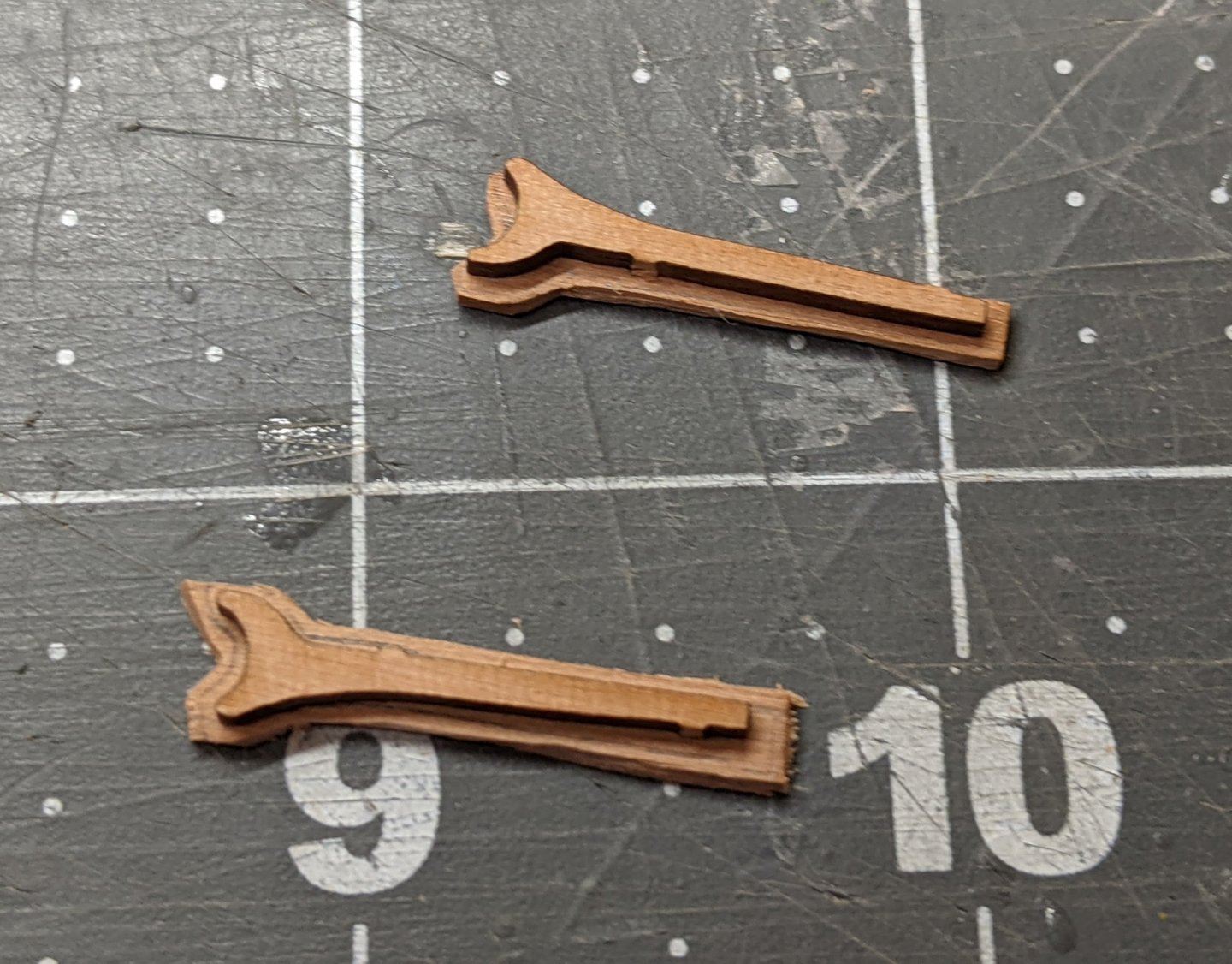
After they had dried I carefully trimmed them down using a combination of craft knife, file and sandpaper until all the excess from the added piece was removed. This left me with what will look like one solid piece once I paint them. You may notice that I left the added bits a little longer than the original piece. The reason for this will become clearer in later pictures, but it was to ensure that I had enough material to properly cover up the entire side of the transom.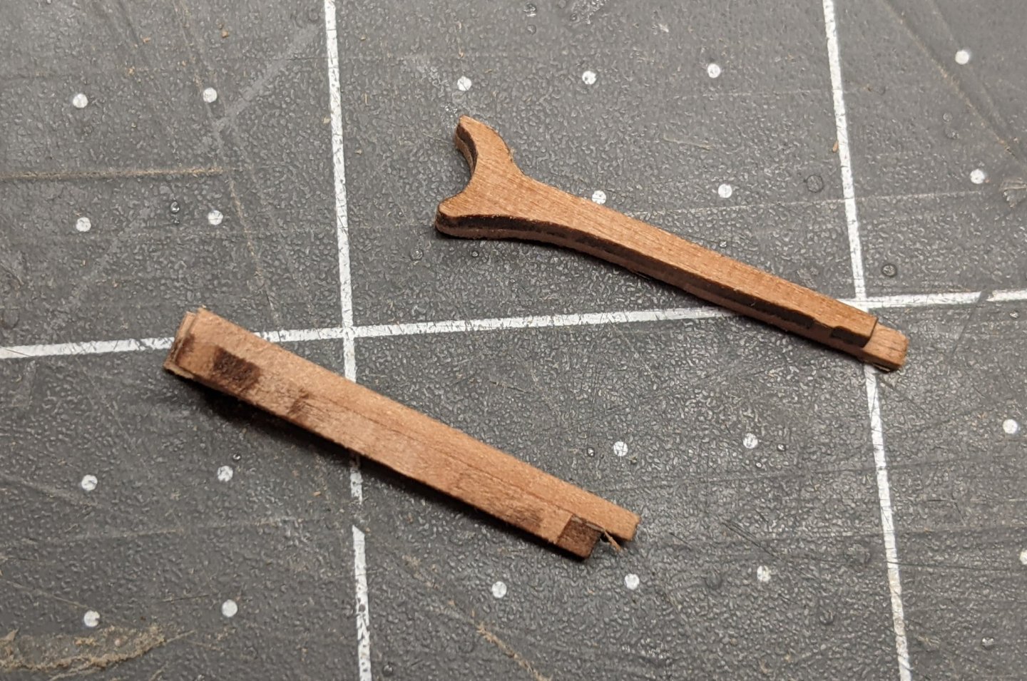
They were then glued to the sides of the transom and further minor adjustments using files and sandpaper were done to ensure the fit.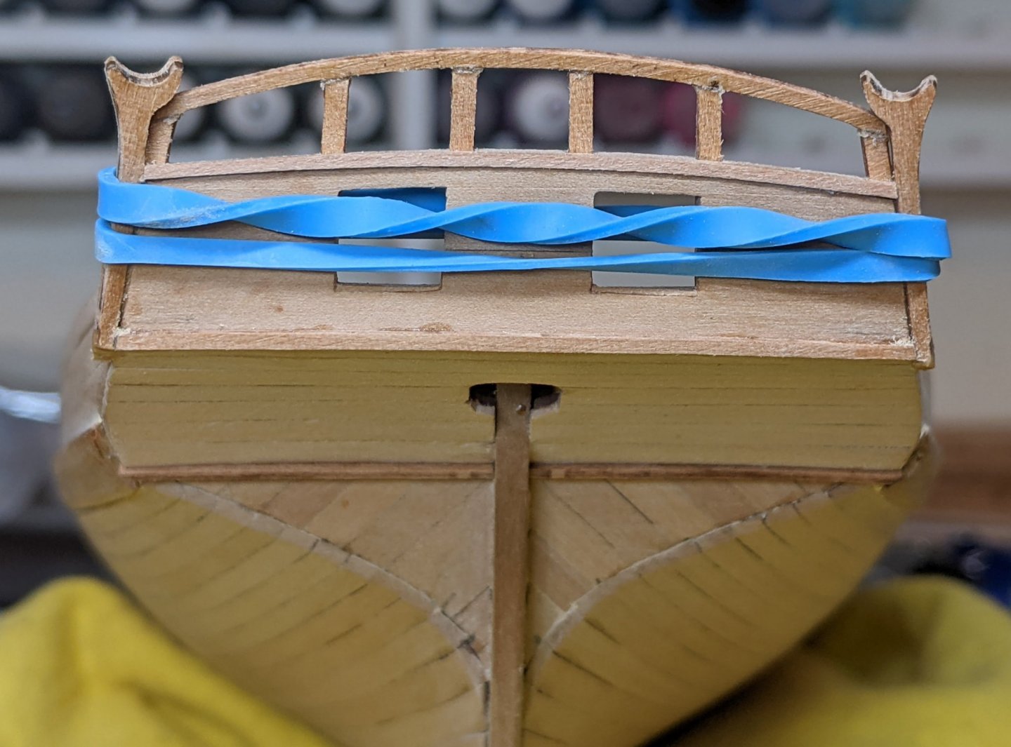
I then used part 76 to form the remainder of the side counter timbers. This was a finicky time consuming task involving significant heat and moisture to get the correct bend. I also had to constantly check and remove more material from the end of the wales to ensure everything lined up.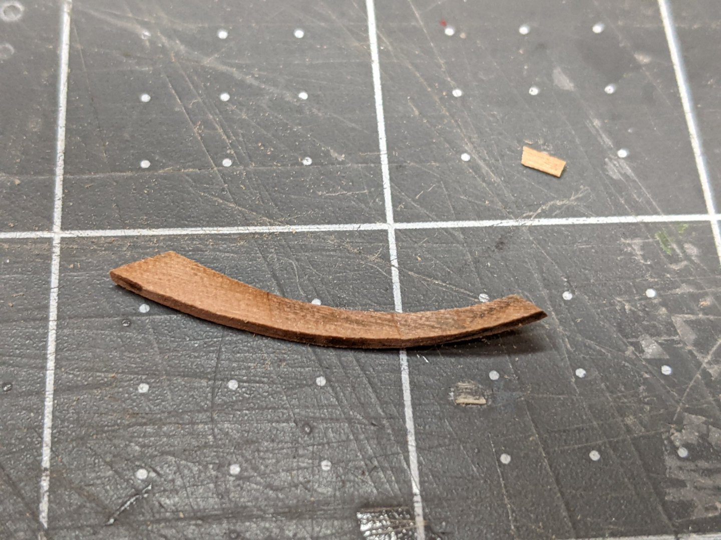
I ended up with some significant charring (due to the iron) on these pieces, but since they will be painted black I am not too worried.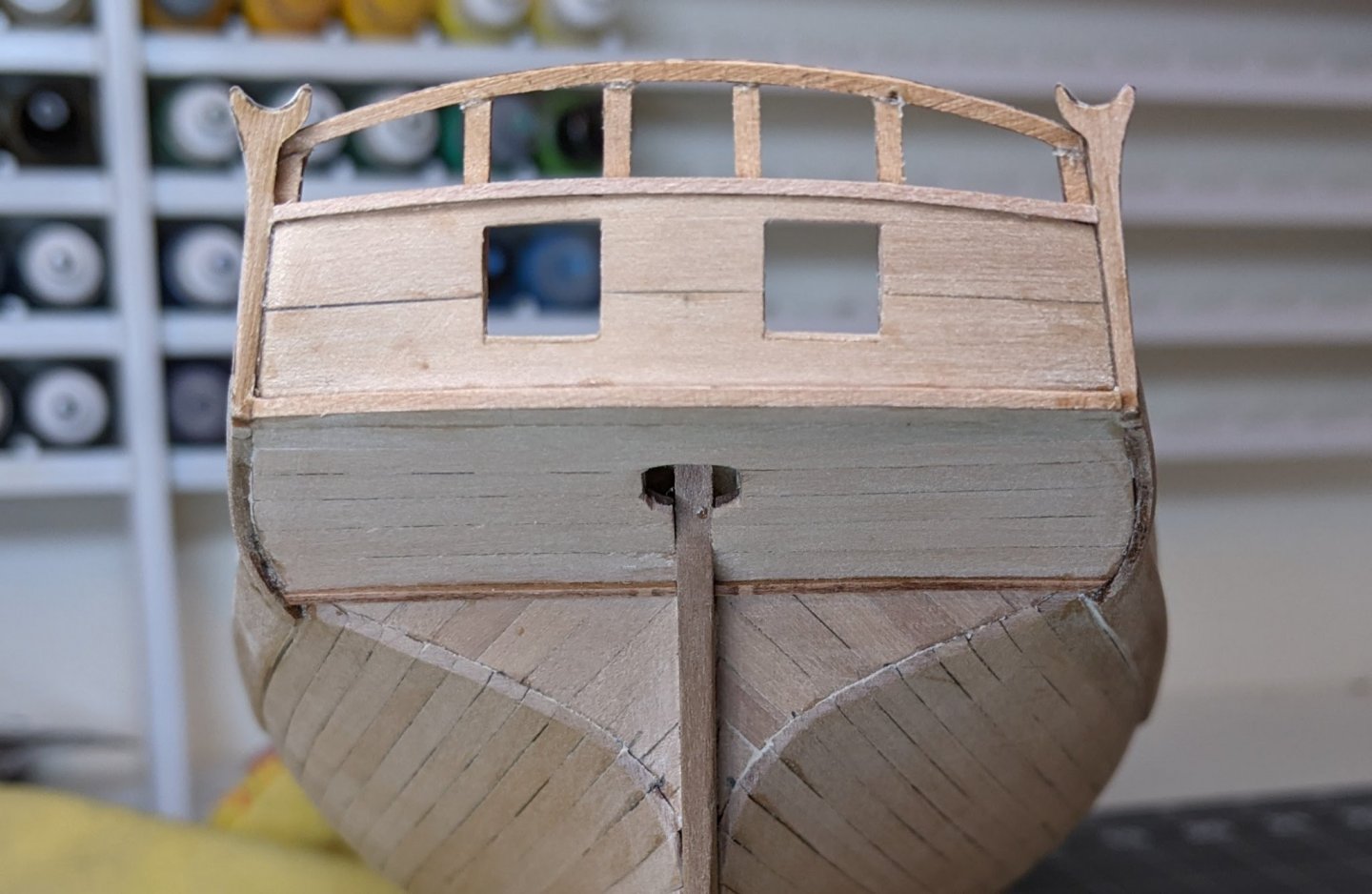
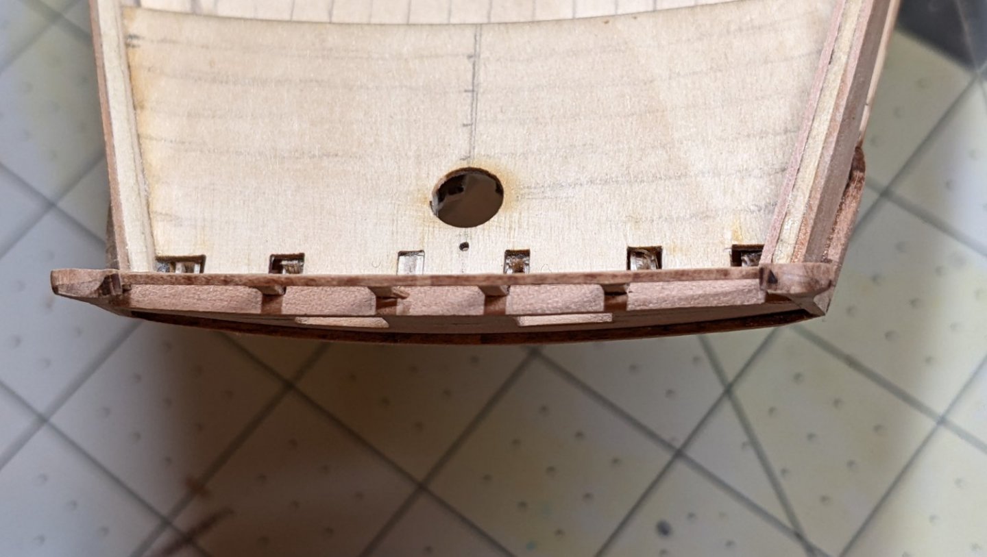
I also didn’t have quite enough length on the pieces running along the side of the transom so I used a tiny bit of sawdust and wood glue to fill the small indent right by the counter. You can see where I did this in the picture below. It looks like there is a gap, but really it is filled in with my homemade filler.
And with that the transom is pretty much complete and is much stronger than it was after part one.
I may take a bit of a break from the ship for a little as I have some other hobby projects that I want to get back to. When I do return to the project I will begin work on the inner bulworks and the deck.


HMS Speedy by Theodosius - Vanguard Models - 1:64
in - Kit build logs for subjects built from 1751 - 1800
Posted
Looking really good. I am also also humming and hawing about colours and finishes. From my tests with wop it seems to give more of the deeper brown on pear that you are looking for.