

Thukydides
-
Posts
1,369 -
Joined
-
Last visited
Content Type
Profiles
Forums
Gallery
Events
Posts posted by Thukydides
-
-
-
-
Welcome to MSW. Good luck on your journey here. I also came from the sci-fi plastic modelling world and while some of it translates, working with wood is a different beast and you will make a lot of mistakes along the way.
A few suggestions to help you get the most out of MSW and help you on your way:
- Read all the other logs on your ship you can. Many will talk about the challenges they encountered helping you to avoid them.
- If you run into issues contact the authors of those logs, most are usually happy to help.
- Don’t only post in your log. Look around, see what others are doing and encourage them as well.
- Treat every step as its own project. You will never regret going too slow, but you might regret rushing through something. This is a marathon not a sprint. I have been working on my first build for almost three years and my only regrets relate to the times I decided it was good enough instead of going back to fix something.
Good luck
- Old Collingwood and Gaz
-
 2
2
-
27 minutes ago, Charlie pal said:
Hello all, hope all are well,
I realize that back in the day, yards that were secured to masts, were movable to adjust sails to account for wind conditions. In our modeling world, that seems impractible, given the intricate task of rigging the blocks etc. So, should the yards be permanently glued to the mast?
….thank you….CharlieYou will likely find that the rigging will be easier if you pin and glue them to the mast. You don't technically have to, but you will make your life easier if you do. Just make sure you measure many times before you start drilling holes.
Also on a related note do as much work off the model as you can, so attach as many blocks to the yards etc off the model as possible.
-
6 minutes ago, wefalck said:
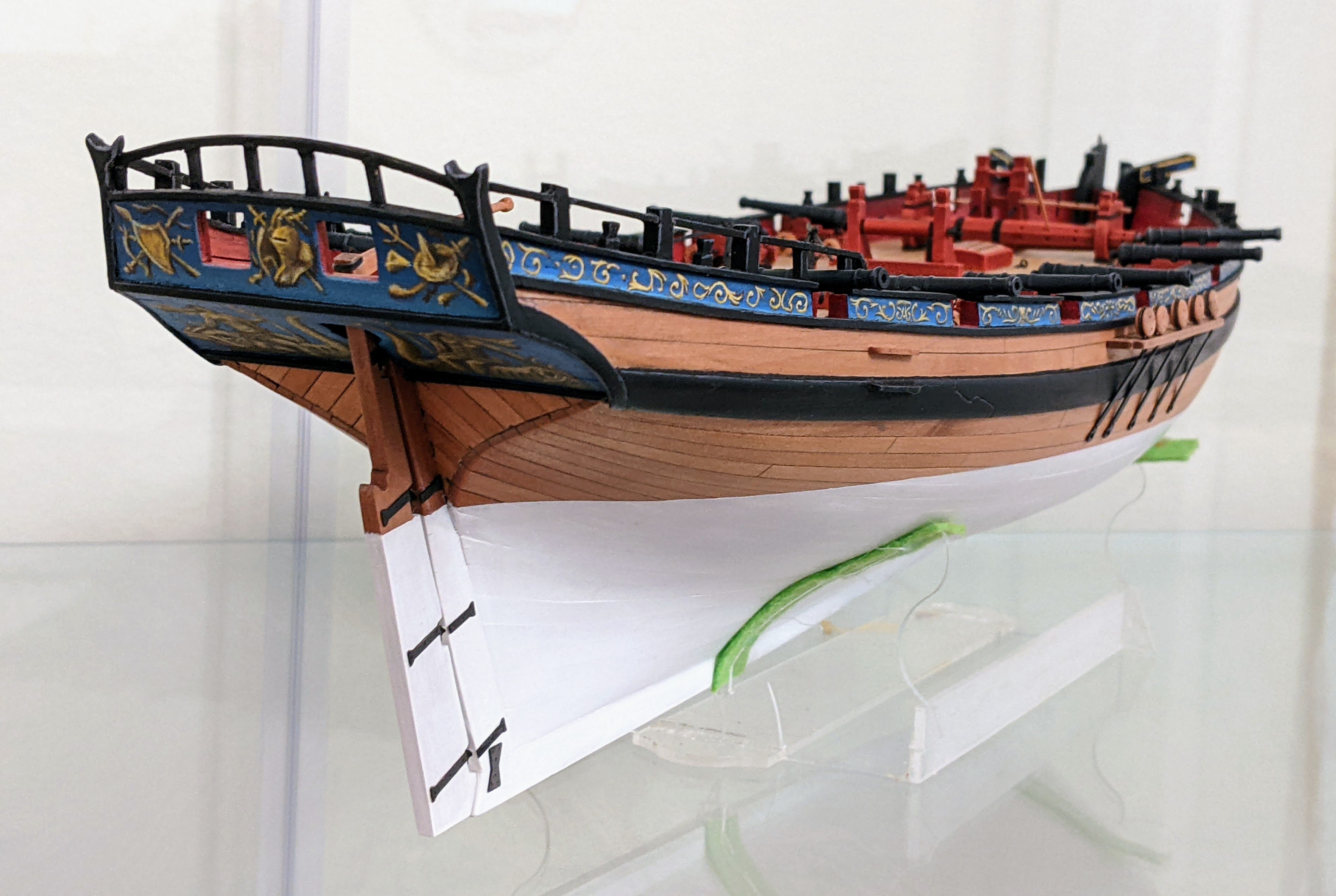
Just out of curiosity: why would there be yard to which only the foot of the top-sail is attached and then above it another yard for the square fore-sail? It seems to be a rather strange arrangement with on first view no practical advantage ...
Not sure on this one, I would guess because the stays get in the way of the topsail so you need to make it with a curved bottom as opposed to a straight one. Then there is a gap which more sail could be put in so you raise the square sail higher.
You can see the arrangement in this contemporary model of hawke from RMG:

-
Fantastic, presentation is great, weathering is well done.
For someone who doesn't have a lot of experience painting figures you have done a good job.
- druxey, AJohnson and Retired guy
-
3
-
-
Great job, as always I have greatly enjoyed following along and listening to your thought process.
- Blue Ensign, mtaylor and hollowneck
-
2
-
 1
1
-
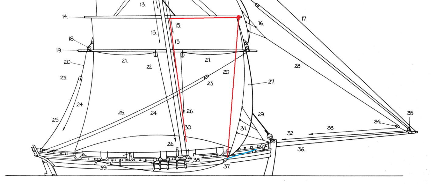
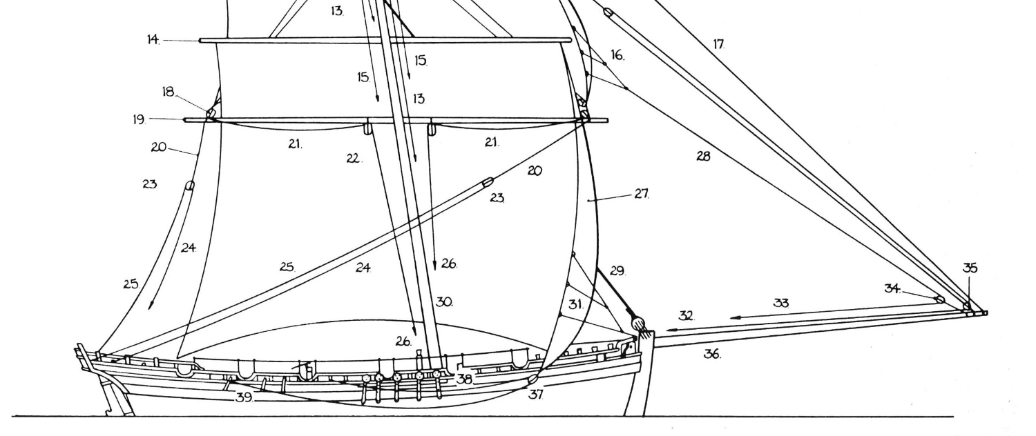
I am trying to figure out the best way to rig Alert's sheet and tack lines to the square sail without having sails in place.

In the above diagram from Goodwin you can see the sheet block (#37) and the sheet sanding and running parts (#s 38 and 39). He does not show it here, but there is also a tack line going from the clew of the square sail forward.
I am not putting sails on my model, but I wanted to show as much of the running rigging as possible. I know convention is to attach the sheet to the clew line and I plan to do this for the topsail, but for the square sail there are no clew lines. I am wondering if anyone knows:
- Why there are no clew lines for the square sail
- What would be the best way to depict the sheet and the tack for the square sail where I am not planning on using sails. I had considered attaching them to the reef tackle (see below for a potential arrangement, red line being the reef and blue being the tack), but am interested in any ideas you might have.
-
5 hours ago, wvdhee said:
I might do that yes, or rigging them off ship to have more room and then install all at once?
Yes rigging them off the ship using a jig is way easier. If you take a look at my log I show how I did this for the gun tackle. On the breaching ropes I would recommend not attaching the ring bolts to the cannons (I had a harder time because I didn't think of this at the time), that way you can do the entire rigging of the breaching rope off model on a jig and then glue them in as you attach everything to the model. I saw a log which did this recently, but I can't remember where. If I find it I will post a link for you.
-
-
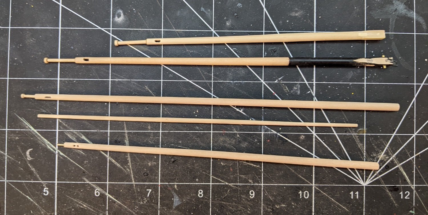
Log #73: The Yards
I have spent the last couple weeks working on the yards and masts. As before I have been using my drill and lots of masking tape to prevent the chuck from damaging the yards while being turned.
I decided to put some extra effort and make the octagonal centre portions for the spreadsail, squaresail and topsail yards (the topgallant at this time appears to have been rounded in the middle). I did briefly consider adding battens, but my research suggested that this did not start being common practice till later. If you are interested in the reasoning behind this I would recommend taking a look at this post in @Blue Ensign’s log as he comes to the same conclusions I did and I don’t feel like it is worth repeating his excellent explanation.
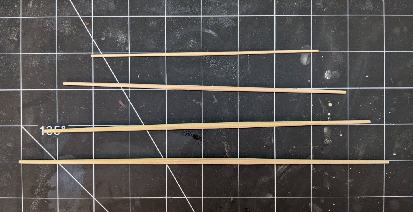
To make the squaresail and spreadsail I bought some square poplar dowel from a local store and used a mini plane to get the octagonal shape before turning them on the drill. Since these will all be painted black the wood colour difference doesn’t really matter.
I realized that I had made an error on my topgallant mast as I had made the upper sheeve on the same side as the lower one when they are meant to be perpendicular to each other. The reason for my mistake is mostly due to this being erroneously shown in one of the Goodwin drawings. So I had to use some filler to move the lower one as it will be painted and so the filler not visible. If you look closely you can see I also made the same mistake on the storm topgallant mast.

Further to my previous post I also made some extra yards and masts to show on deck. In order from top to bottom they are:
- Storm topgallant mast
- Topgallant mast
- Mizzen mast
- Mizzen yard
- Outrigger
I decided not to do either the storm gaff or the driver boom mostly because I didn’t feel like making them and I figured the above 4 will be enough to illustrate the idea.
And that is as far as I have gotten, not a lot of progress to show, but getting all the masts and yards made is a big step and next up I can move on to painting them and attaching everything to them.
- wvdhee, KARAVOKIRIS, Glen McGuire and 15 others
-
18
-
1 hour ago, rvchima said:
I will admit to complete ignorance on this.
Who is Lavery?
If I search for Sphinx on https://www.rmg.co.uk there are zero results. Is there a separate site for research?
Sorry I should have been more clear.
You probably searched the website not the collections. See below for a link to my sphinx search:
https://www.rmg.co.uk/collections/objects/search/sphinx
The plan I was refering to was this one:
https://www.rmg.co.uk/collections/objects/rmgc-object-83709
@ccoyle is correct, I was referring to Brian Lavery and his book called the arming and fitting of english ships of war which is one of the better reference books out there for the fittings on english warships of the period. The NMM MID/9/2 is in reference to the primary source he quotes, the record number at the National Maritime Museum Archives.
https://www.rmg.co.uk/collections/archive/rmgc-object-511162
-
-
2 hours ago, wvdhee said:
If I may quote from "Winfield, Rif. British Warships in the Age of Sail, 1714–1792: Design, Construction, Careers and Fates . Pen & Sword Books. Kindle Edition. " (if not, please remove) which says about the Sphinx class:
" Guns: UD 20 x 9pdrs; QD (from 1794) 4 x 12pdr carronades; Fc (from 1794) 2 x 12pdr carronades. Daphne and Ariadne were re-established in early 1793 with 2 x 4pdrs on QD and 2 x 4pdrs on Fc in lieu of carronades, and re-rated as 24-gun ships "
Coppering was done in 1781 btw.
Much of what Winfield says is helpful, but I would not rely on Winfield other than as an outline or starting point for research, I have found a number of instances with regard to the Sphinx class where what he says is contradicted by primary sources. If you are really interested I could give you more detail via PM, but I don’t want to bog down @rvchima’s log anymore than I already have.
-
1 hour ago, rvchima said:
Just to make sure that I understand, around 1782 Sphinx had 6 12-pounder carronades added to her quarterdeck, and possibly 2 more to the forecastle, in addition to the 20 9-pounder carriage guns on the gun deck. Is that correct?
Yes, the official establishment rating for them was to have 8 12pdr carronades, two on the forecastle and 6 on the quarterdeck.
Lavery in his appendices has a list from 22 July 1782 showing the ships which had been supplied with carronades (nmm mid/9/2). Sphinx is on this list and is only listed having the 6 on the quarterdeck.
If you search sphinx on rmg they have a planking expansion taken in 1808 before she was broken up. This shows sphinx having built up bulwarks on both the forecastle and quarterdeck. Now sphinx was last paid off in 1799 so in all likelihood this is what she looked like then.
So the question is do you believe the 1782 list and if so when do you assume the extra carronades were added.
To complicate matters there is another list from 1794 showing all carronade armed ships and this time sphinx is not on the list though her sister ships are.
Basically there are no easy answers on this one. As you could probably make a credible case for either 6 or 8 I would say do whichever you like better.
-
1 hour ago, scrubbyj427 said:
Amazing detail on this resin print, now I need to attempt painting him. So far he seems pleased with the progress and I wouldn’t dare argue with an armed Captain.
He is great fun to paint, lots of nice detail, I also like the way he is posed and the flow of the clothes, it feels natural where to put the highlights. Though mine was smaller (1/64th), I found the details lent themselves well to being brought out by paint.
If you are planning to remove him from his base go slowly as the resin is a bit brittle.
- scrubbyj427 and mtaylor
-
2
-
-
Welcome back. Good to see you at it again. The damage sounds incredibly frustrating. Good job on sticking with it and getting the repair done.
You might want to take a look at the crutches as I can't tell for sure from the photos you have, but the bottom of the should connect to the curved piece on the side (I forget it's name). There appears to be a gap on your pictures.
-
-
1 hour ago, rvchima said:
😬 Yikes! I was afraid that other changes would show up in six years. Since the coppered hull is much more obvious than gun barrels to the casual observer (like me), I think I will copper the hull and ignore a few years of historical inaccuracy. But thank you kindly for the information.
Alternatively you could portray her as one of her sister ships.
I believe Daphne, Galatea, Ariadne launched in 1776 and vestal in 1777 were coppered at launch. I know for sure Perseus and Unicorn built by contract in 1776 were.
Also I believe you can buy carronades from Vanguard which if you wanted to add wouldn’t be very hard, especially if you didn’t bother to build up the bulwarks. If you did this you would want to use the early sliding bed ones.
At the end of the day most people looking won't know anyways 😄.
-
1 hour ago, rvchima said:
Spoiler Alert - I am about to copper the hull. The Sphinx was coppered in 1781. Would the copper go under, over, or around the iron reinforcement plates? Same question for the rudder hinges.
Just as a note, if you are displaying her as coppered (like she was in 1781) then you should know that at that time she was also given carronades around the same times as many of her sister ships were.
She appears on a 1782 list saying she was armed with 6 12pdrs on her quarterdeck, but then later in a 1793 she is not on a list of carronade armed ships. Sometime before 1799 her bulwarks were built up on the quarterdeck and forecastle (likely when she received the corresponding armament, but it is impossible to know for sure).
So given your time period I would guess the most correct armament would be just the 6 12pdr carronades on the quarter deck, with correspondingly built up bulwarks, but you could probably also make an argument for adding the 2 to the forecastle as well.
EDIT: I should add both the 1779 and the 1794 establishment lists say that 20 gun ships should be equipped with 8 12pdr carronades, 2 on the fore castle and 6 on the quarterdeck, though in reality many ships did not adhere to the establishments.
-
I have never painted silk span before, but I imagine you would want to stretch it while wet to make sure it drys taught. You could take a look at this video where the person doing this doesn’t use a frame, but stretches it while wet so it dries flat.
It is also potentially you could be painting the layers while the previous layer is still not fully dry. This is a big no-no in acrylic painting as you reactivate the previous layer and make your surface less smooth.
- Cathead, Archi, Mark Pearse and 2 others
-
5
-
3 hours ago, mcpwilk said:
Superb modelling to date. I enjoy splicing but splicing scale ropes is a little more taxing than splicing full size ones!
Having a scale figure helps improve perspective. If you want to try some larger scale Nelsonian sailors, the Victory Miniatures web site is worth a look (https://www.victoryminiatures.co.uk/index.php?id=about).
Mike
Thanks. Yes it is a bit of a pain, but I have found it looks way better, though as mentioned I still havn’t come up with a methodology I am completely happy with. I need to do a bit more experimenting.
With regards to the scale figure, I do indeed have one. If you scroll back up to Log #68 you can see me discuss how I painted him.
- Glen McGuire and AJohnson
-
2


HMS Sphinx 1775 by Ronald-V - Vanguard Models - 1:64
in - Kit build logs for subjects built from 1751 - 1800
Posted
Looking good, nice careful work.