

Thukydides
-
Posts
1,355 -
Joined
-
Last visited
Content Type
Profiles
Forums
Gallery
Events
Posts posted by Thukydides
-
-
Sometimes there are things I see on this site which inspire me because I think you know if I keep pushing myself and learning, maybe someday I will be able to do something like that.
Then there are posts like this which frankly depress me because they are so much better than anything I can even imagine doing. Awe inspiring work!
- HAIIAPHNK, mtaylor and Keith Black
-
 3
3
-
2 hours ago, DaveBaxt said:
although I am having difficulty understanding the tables( probably due to the writing and mpoor eye sight)
For your purposes both tables say a 38 gun frigate carries 42 5.5 in cir breeching and 15 4.5 in cir. The second table states they have a length of 30 and 23 ft respectively. Obviously they would have needed spares, but it would be odd if the carronades were not included in this. I will take a closer look through all the tables and report back if I find any further details.
-
16 minutes ago, allanyed said:
Great stuff Daniel! Can you share the source of these pages? Thank you
Allan
They are from ADM 160/150 (https://discovery.nationalarchives.gov.uk/details/r/C2980865), a book of lists of proportions for ordnance, I have photos of most of the book. It has all sorts of lists regarding powder etc.. Most of it seems to be dated 1794, though there are a few loose pages dated 1781 and a few from early 1800s. I am working on transcribing some of it, but there is a lot to go through and so my work has focused on stuff that I immediately want answers to.
One thought I did have, if I have the time is to look at the charge sizes for carronades vs guns. The size of the charge is what would determine the force since they were firing essentially the same size of cannon ball. That might give some indication of the relative size of the breeching rope.
-
30 minutes ago, Glenn-UK said:
This morning I added the final ratline when I completed the mizzen topsail shrouds.
That must be a relief. I only had a few to do on Alert and I did not enjoy even the little I had to do.
It is looking great, she is very imposing.
- Mr Whippy, Theodosius and AJohnson
-
3
-
8 minutes ago, cdrusn89 said:
keeping the hull stiffeners in place is not that easy.
You could glue them in place with some white glue and then remove it later with a little isopropyl.
-
See below for an excerpt from ADM 160/150. The dating on this is hard as there are not dates on every page, but seems to be around 1794. I forgot to copy the headings over but they are the same as the next picture I will show.

There is also this table which occurs right after a table of carronade sizes:
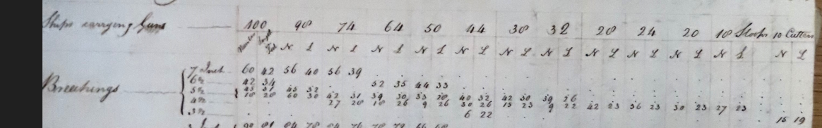
The problem is that the size of the ropes doesn't seem to necessarily vary with the size of the gun. For example in a table in the same document a 28 gun ship is listed as having 24 9-pdrs and 6 4pdrs, but it is listed as only having one size of breaching rope. They are also listed in another table in the same document as carrying 4 24-pdr carronades, but the only breeching rope size listed is the same as for the 24 gun ships which carried 18-pdr carronades.
To confuse matters more the 44 gun ship appears to have exactly the number of the smallest size of breeching rope for the 6 6pdr guns it would have carried, but none of this size is used on any of the other ships that carried them other than the cutters.
I am wondering if possibly they tried to carry as few sizes of breeching ropes as possible and so they just used oversized ones on their smaller guns in some cases to simplify the supply chain for the ship.
-
She became the HMS Hussar for a couple years, but there are no plans on RMG that I could find. She was sold in 1803. Just so you don't get confused there are plans for an HMS hussar of the samish size on RMG, but they are for Hussar 1804 and Enterprise class ship which got the name after the American capture was sold in 1803.
https://threedecks.org/biyun/index.php?display_type=show_ship&id=4821
Note according to three decks protector was 26 guns, now their source would have been Winfield which I have found to sometimes not be completely accurate in the details.
A quick search of the national archives turned up these entries:
Capture of Protector
https://discovery.nationalarchives.gov.uk/details/r/C13507396
Hussar Captures other ships:
https://discovery.nationalarchives.gov.uk/details/r/C13508024
https://discovery.nationalarchives.gov.uk/details/r/C13507757
I couldn't find any captains logs, but there might be something if you go digging.
-
-
Thanks Alan for taking a look.
I also have been digging into this more. My first thought was to take a look at Steel. There are a number of plates in the elements and practices of seamanship which may shed light on this question, for example see below.

But all of the images like this one are not high enough resolution to really say for sure. Once you start to zoom in you can’t quite tell if they are served or not.
I did some more reading of Lees and he has the following to say on p162 after noting that these things have not changed much since the early days of sail:
QuoteAs regards the question of whether to serve the straps of the blocks or not, there are two trends of thought - some like to serve them to keep the weather out of the strap, while others like to leave the straps unserved so that any signs of wear or rot are visible… …however it certainly was the practice to serve such exposed straps as those round the tack block, where the sea could easily get to them. I therefore suggest serving all large and all exposed straps, all straps where they could be chafed, such as those on the yards, and leave the rest of the straps unserved.
Now what constitutes a large strap is up for debate, but I would guess based on this that Lees would recommend serving all of the straps attaching blocks to the yards. This does make logical sense, but as of yet I have been unable to find any primary sources which confirm this.
On the balance I think I will probably serve them as I have already served most of the blocks I have been attaching to the mast and yards using a single long strop and logically if I was doing it for them, this shouldn’t change for using a lashed strapping. However, if anyone has any sources the can point me to which either confirm or contradict this line of thinking I would be interested in looking at them.
- Theodosius, mgatrost, Pitan and 4 others
-
7
-
36 minutes ago, AON said:
I have to say I am amazed at your splicing at this scale!
You are serving the entire strop but the image does not depict the strop to be served.
Is that extra work for you, or did the image simple not show it?
Thanks Alan. This is also your scale so all of this is in your future 😄.
The image in question is just showing how the block is lashed. Separately Lees mentions that all ropes which could experience rubbing were served.
I interpreted this as meaning that I should serve these blocks as they will experience chafing on the yard. That being said I don't know this for sure and would be curious if anyone can answer one way or another.
It is on my to-do list to do some more reading of primary sources on naval seamanship to try and better get clear in my head what should be served, what knots to use when etc...
Edit: It would certainly be easier if I didn't have to serve them.
Edit2: Part of the reason for me assuming they were served is that Goodwin depicts them as such in his illustration of the topsail clew blocks. Now this is not the blocks in question, but if the clew blocks were attached using served line I would imagine the sheet blocks which are under much more strain would have been too.
- mgatrost, jpalmer1970 and Glen McGuire
-
3
-
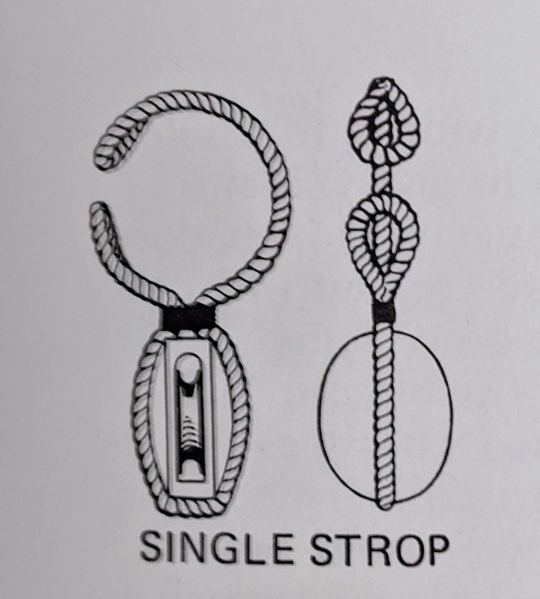
Log #77: Experiments in Lashing
Thank you to everyone for your kind comments and encouragement.
I have succumbed to feature creep once again. I was doing some investigating on how to lash the blocks that run the falls of the topsail sheets to the spreadsail yard and realized that I could make significant improvements to how I attach blocks to the yards. Though I am unwilling to go back and redo my past work, I figured since the yards will be a fairly prominent feature of the model I might as well do it right going forward. Also I have always thought of this build as an experiment and frankly there are parts of the build which are at a much lower standard than others.
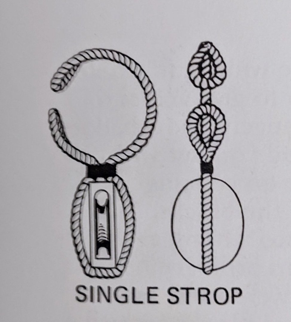
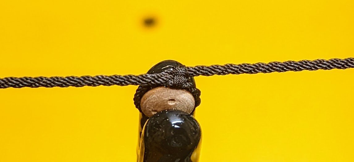
The above image from Lees shoes what I am trying to achieve, a loop on each end of the block strapping which are seized together around the yard.
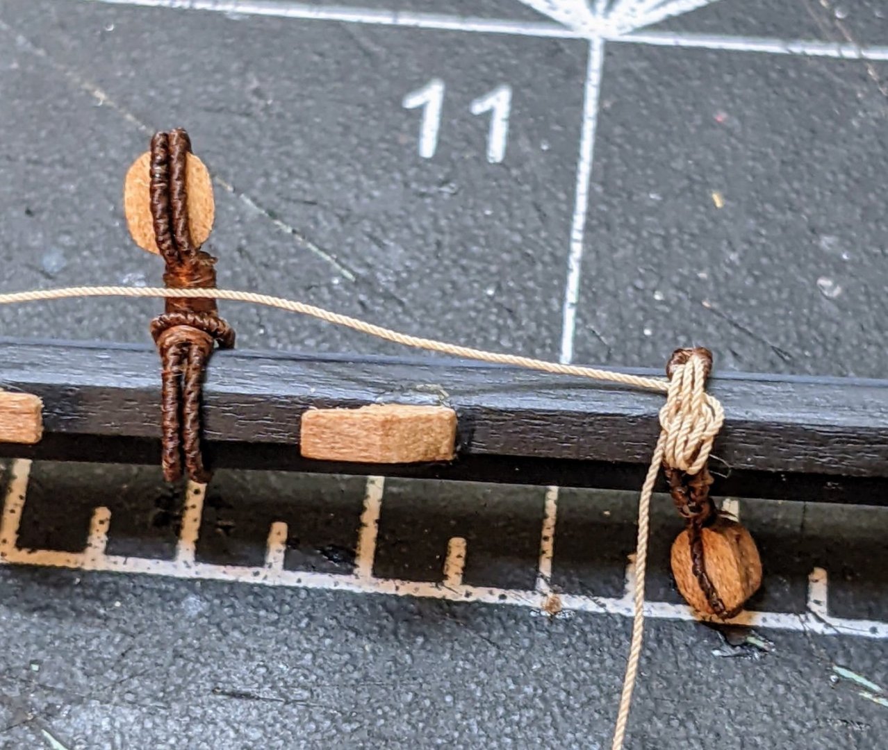
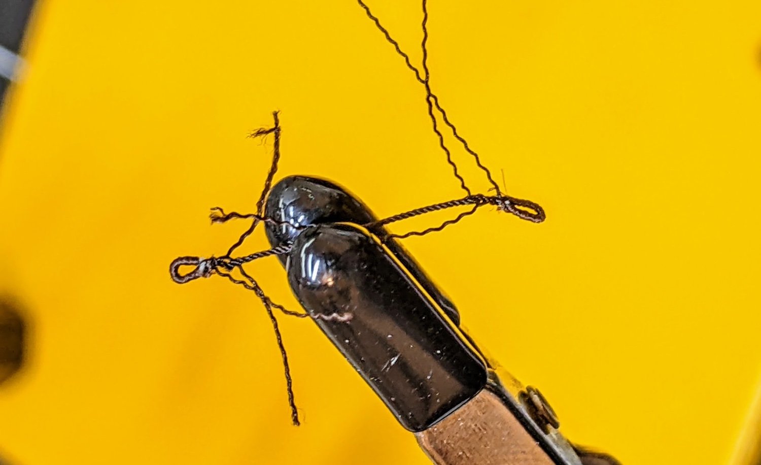
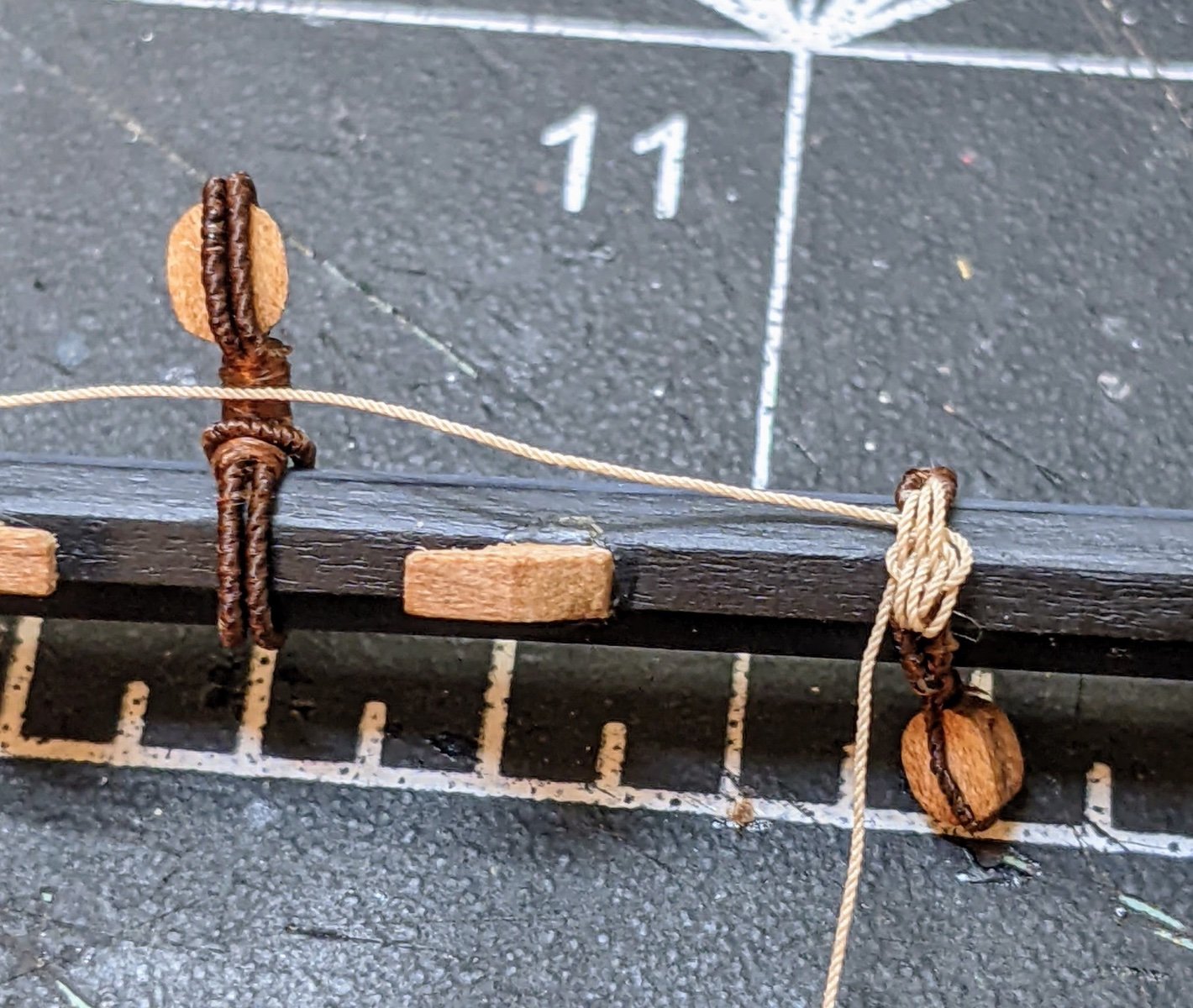
The first step was to try and create the small loops. This is easier said than done at this scale and in particular since I am trying to serve the entire length. After about 7 attempts I got one that was passable. First I served two short sections on the rope where the loops would be. Then I spliced them into the rope as can be seen in the picture below.

I secured the splice in place with fabric glue and once that was dry I served the rest of the rope. It was then fairly straightforward to size the rope to the block.

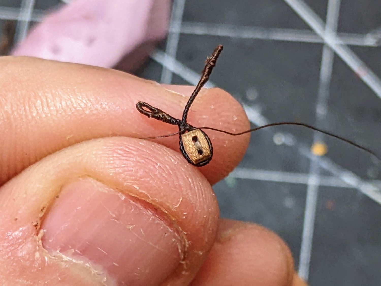
As you can see I still have some ways to go, but the above example is at least starting to look the part. One thing I have discovered is that I need to be really precise with both the amounts of glue I use and also how the ends of the serving are secured. Small issues become quite visible on the loops.
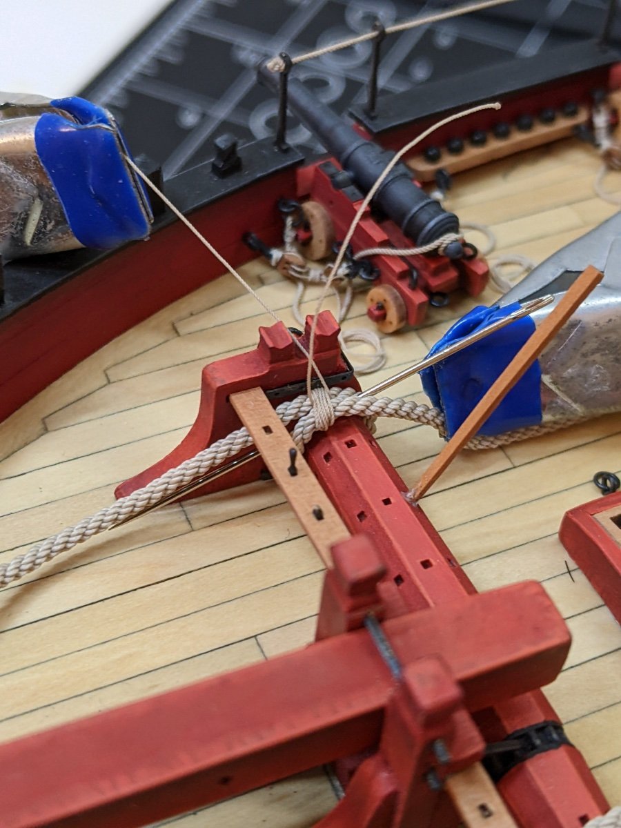
Next up was the question of lashing the two ends together. I started testing this out, but realized that the 0.25mm rope I have was too thick. I have since ordered a smaller size of rope from Ben (the same size I used for the ratlines, just in a tan colour). Once I get that I can start to experiment with this more. But you can see a WIP version below where I attempted (with only partial success) to create a rose lashing.
Well that is as far as I have gotten. I still have some tests to do and also I need to wait for the thinner rope for the lashings to get here.
-
-
On 3/13/2024 at 4:02 PM, jfhealey said:
but I don't see how that can be effectively painted except with an airbrush.
Thanks for your thoughts
Sorry I never noticed your response.
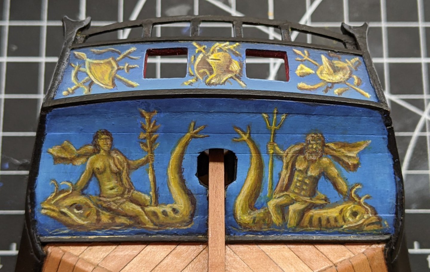
You could look into glazing with a highlight in the middle of the curve. Basically you use very watery paint applied in thin layers to blurr the transitions. See the below picture which I did entirely with a brush. I talk about the method more in my build log of you are interested in more details.
In any case fantastic job.
-
Looking good.
I realize this is a somewhat minor point but the bottom sizing is done with the ends of the shrouds heading in opposite directions. See below picture below (note as I was using cable laid rope the direction is reversed from what you would do with your shrouds).
The next two seizing would be as you have done them. Also the way you tie them off is to pull the end through the gap and wrap around under so it holds it. Again see below picture.
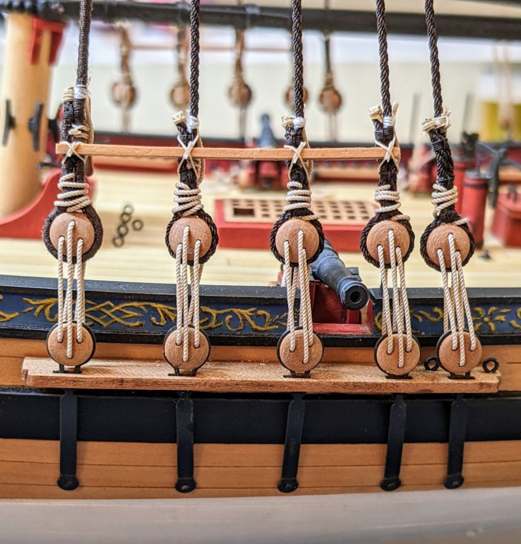
You can't see it in the picture but the bottoms loop goes under the lanyard coming through the gap to secure everything.
None of this is necessary, but if you want to make it look a little more authentic these are some small adjustments you can make.
-
@wvdhee is correct. I would recommend taking off all of them and making sure you edge bend them enough. You will have a much easier time if you take them off and do it right now then if you try to compensate. Take your time and treat every plank as its own project.
-
43 minutes ago, mugje said:
Will be interesting to see how much difference there will be between the standard supplied blocks and the pear wood set.
I have the idea that the items are so small...that I wouldn't really see the difference, but who knows
")
Oh the pearwood ones are way better. If you look at my log you can see some up close photos of them.
I would highly recommend picking them up while he still has them in stock as no more can be gotten due to the war. The syren ones are also really nice, but they sell out so fast that it is hard to get them in the sizes you need.
I am of the view that for a relatively modest cost your model will look significantly better if you upgrade the blocks and get some better rope.
-
5 minutes ago, Isaiah said:
Such clean work, looks very nice.
Excuse me if this has been mentioned, but is this the cord that’s included in the kit?
I’m looking at purchasing a kit by Vanguard.
Thanks Isaiah. The rope I used was purchased from @BenD (ropes of scale). He produces some very nice rope in a wide variety of sizes and colours. He has even done some custom sizes for me. I am using his polyester rope (the anchor one is the cabled type). It has some upsides over natural fiber (no fuzz, higher definition), but also some downsides (stiff, can be difficult to get it to lay naturally, white glue doesn't work on it).
The kit rope is fine and like most of the kit is to a much higher quality than most kit stuff you will find, but not quite as nice as if you go out and buy some rope or make it yourself.
One of the nice things about the Vanguard Alert kit is that it is to a very high quality, but also there is lots of scope for improvements and adjustments. So if you want to do a bit of kit bashing I would highly recommend it. If you want to do the kit exactly as out of the box I would say that the new Vanguard cutter Sherbourne looks really nice.
-
7 hours ago, jpalmer1970 said:
That's a great idea for the knotted handrail - excellent work
Thanks though I can't claim credit. I got the idea from @Blue Ensign's alert log.
- Glen McGuire, jpalmer1970 and AJohnson
-
3
-
Have you tried cleaning the foil with isopropyl or acetone?
If all else fails you could go for a painted aged look. To be honest if I was going to do aged copper that is probably the way I would go. You have a lot more control over where you add the tarnish.
There was one poster on here at one point who discussed using urine to great effect. You can find his discussion of it here.
-
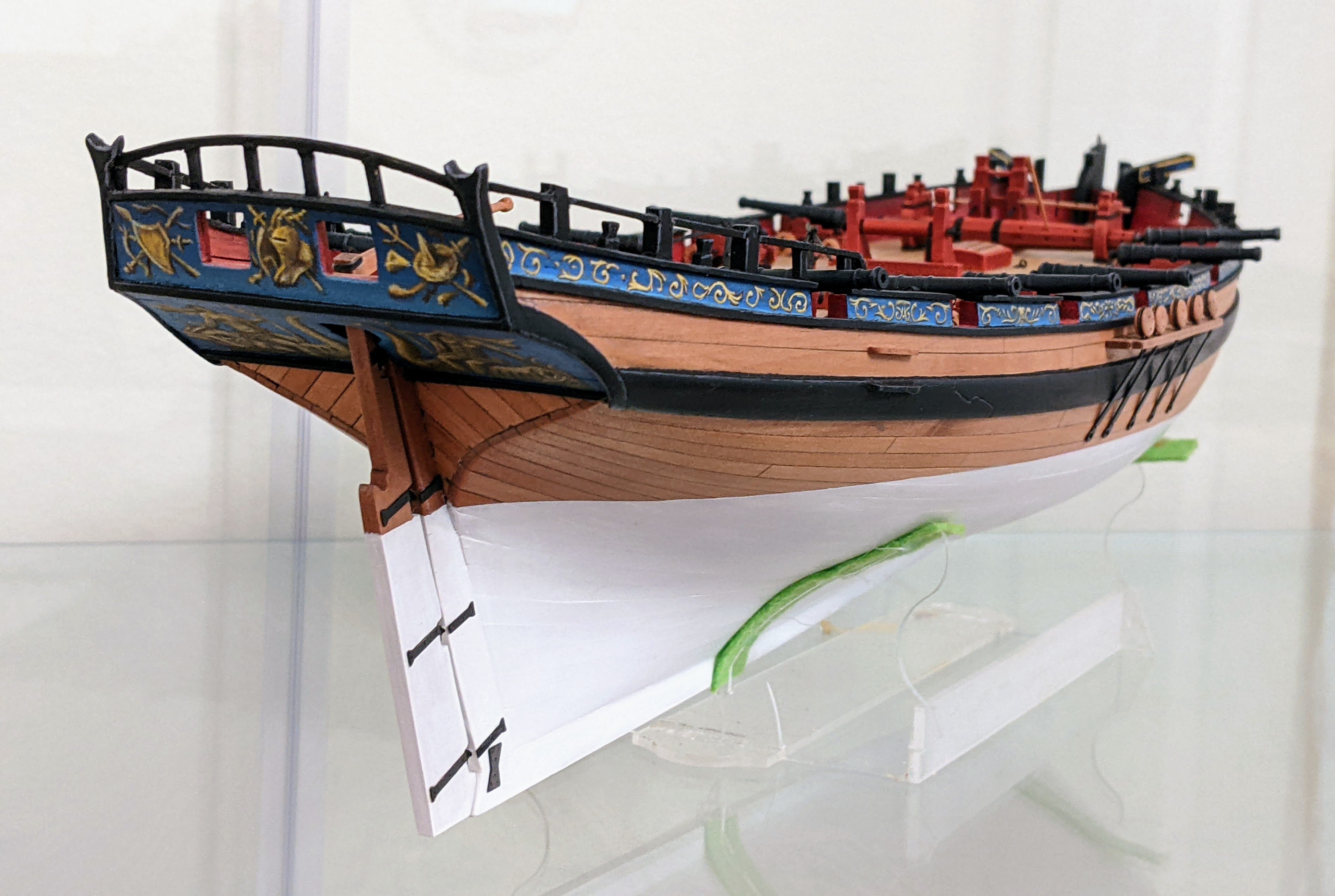
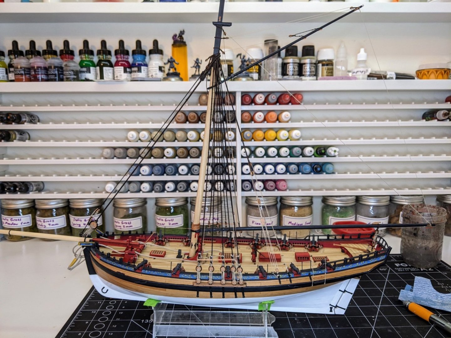
Log #76: Anchor Cable & Rails
I have a fairly small update for today.
I had intended to show pictures of my work on the yards, but after two days of work and 6 failed attempts at rigging blocks to a standard I am willing to accept I decided I would postpone an update on them till the next log post.
In the meantime I decided to secure the anchor cable to the windlass before too many ropes start to clutter the deck.

It is delicate work at this point trying to do this sort of thing without catching anything. I have to make sure I am fully in the zone for this and at all times am aware of where my hands are.
At this point I also replaced the belaying pins which I had previously broken when trying to get the bowsprit in place.
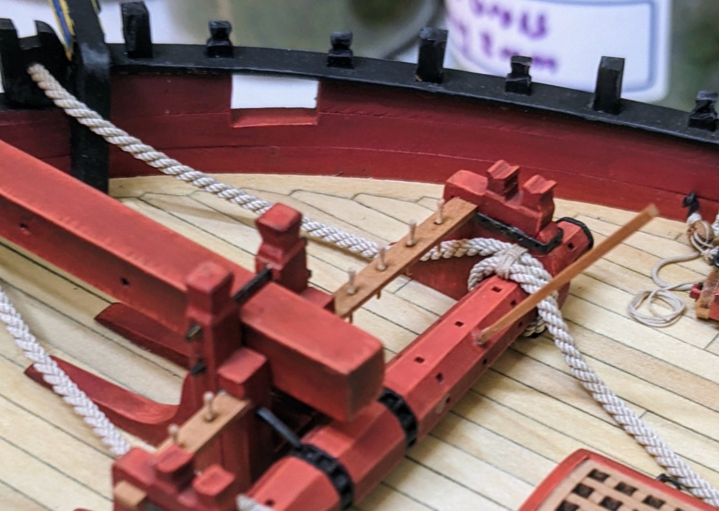
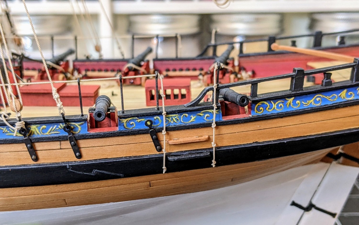
I also decided to get the rope that runs through the stantions in place and to add some knotted ropes to help with anyone trying to get on the ship.

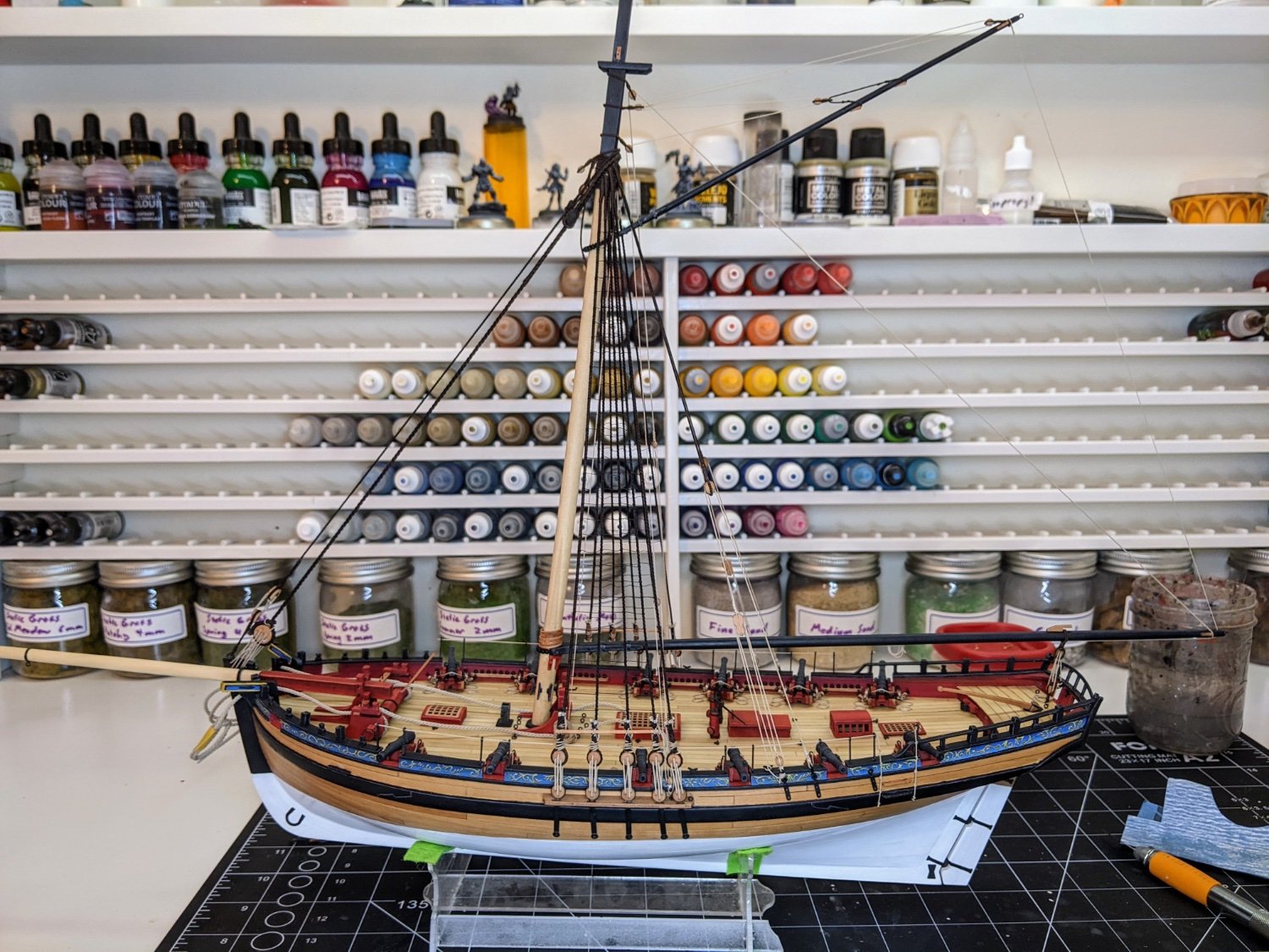
And here is the current status of her. Thanks for stopping by.
- KARAVOKIRIS, mgatrost, AJohnson and 22 others
-
25
-
Hi @AmateurModelBuilder, welcome to the forums.
Your question is a very broad one and there is no way I can answer it in a post, but what I would suggest is the following:
- Start a build log, this is a great way to get help as you go along.
- Look for build logs of others who have done your kit and read them all.
- Search in this section of the forum for specific questions regarding painting. Navigate to here and then in the top right corner there is a search function. Search for the topic in question for example you could search "primer" and you will find lots of posts on the subject.
A quick summary of what you might want to think about with regard to painting is below:
In general when it comes specifically to painting you first need to seal the wood in some way. This can be accomplished through some sort of sanding sealer or by using an acrylic primer. After you prime you need to sand and then add another smooth coat and then sand again and so on. If you want to achieve a look a bit like on the box you will need some masking tape (I use tamiya). As a general rule I use a little bit of acrylic varnish to seal the gap when painting wood as otherwise sometimes it runs down the grain. If you use a sanding sealer this step may not be necessary.
For painting use thinned acrylic paint designed for miniature painting or artist grade acrylics (don't use cheap paint). My rule of thumb is two thin coats, though depending on the colour you may need a third. Always make sure you let the previous coat fully dry before adding the next and sand as necessary.
Take your time, model making is a marathon not a sprint. Treat each step as its own project, I have never regretted taking more time on something, but have frequently regretted rushing.
-
-
14 minutes ago, TJM said:
Hi Allan,
Thank you for your comment! Do I understand correctly that the one hole in the blocks should be closest to where the block is attached? So that when the line runs down, it would appear to go over the (imaginary) sheave inside the block?
Yes, that is correct. As Alan said you could probably just drill a new hole as that might be easier than removing the block and reattaching it.
- allanyed, Ryland Craze and TJM
-
3
-


Gun positions and their associated tackle
in Discussion for a Ship's Deck Furniture, Guns, boats and other Fittings
Posted · Edited by Thukydides
Yes it would move back faster, but the force on it would be the same. If you remember your high school physics F=ma, so a lighter piece with the same force acting on it would accelerate back faster. I wonder if part of their problem was the recoil length. As the carronade was shorter it didn’t have as far back to go before running out of rope so to speak.
I found the following piece of paper which shows charge sizes. Now it has no date so not sure exactly when it is from, but you can see that a 32-pdr carronade (which was what 38 gun ships were rated to equip) is equivalent to the charge for a 12-pdr long gun (inbetween the 18 and 9-pdrs carried by 38 gun ships).
EDIT: Since I know @allanyed is going to ask") this comes from ADM 160/150 as well.
this comes from ADM 160/150 as well.