yvesvidal
-
Posts
3,643 -
Joined
-
Last visited
Content Type
Profiles
Forums
Gallery
Events
Everything posted by yvesvidal
-
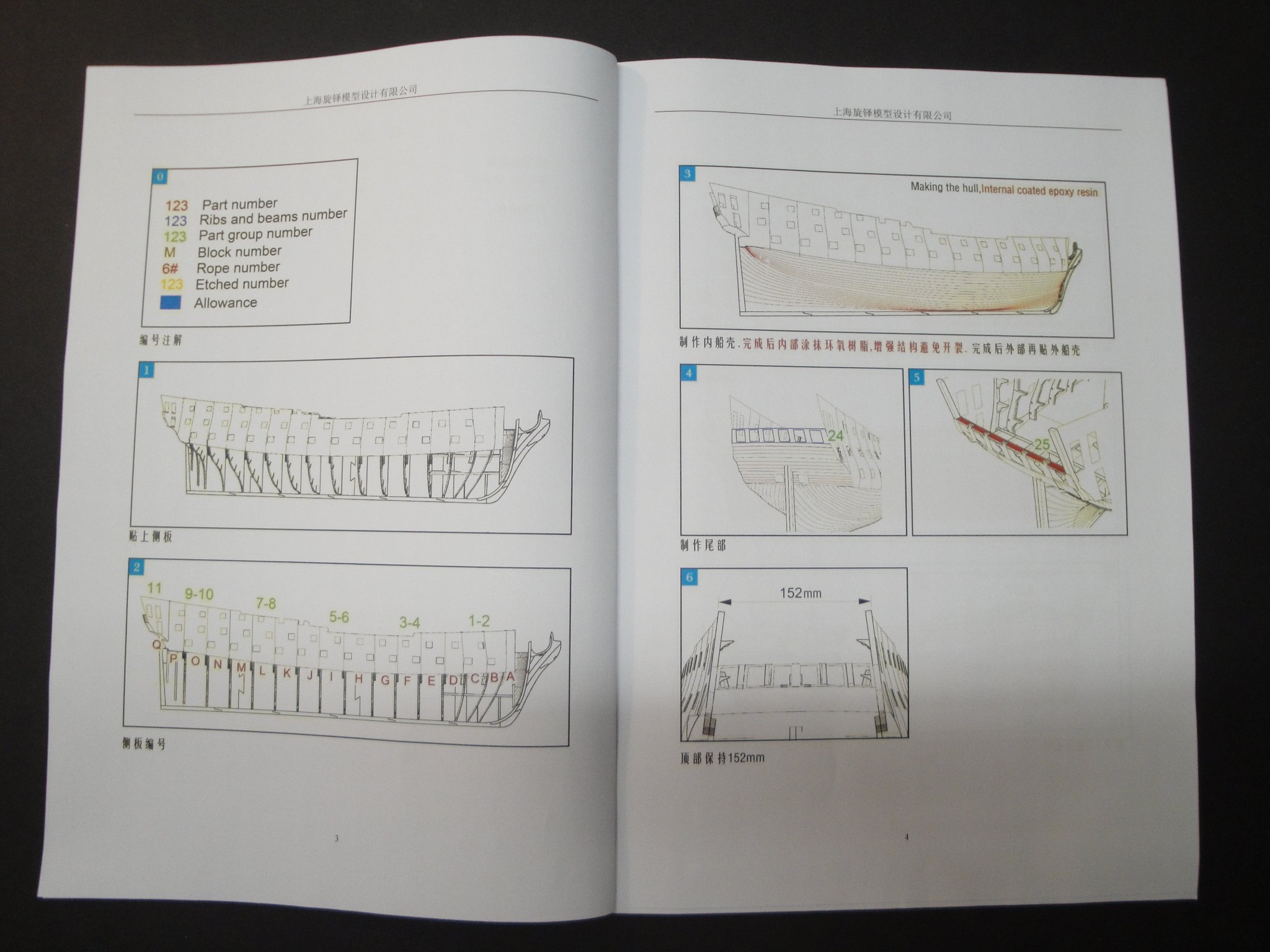
 Patrick, Thank you for your encouragements and praises. Yes, it is not exactly an easy model and a few things have to be ironed out. The kit is evolving and CAF Model is fixing things on the fly, always improving their kits. As a matter of fact, I am corresponding regularly with Tom (CAF Model in China) and he is helping me along the process to build this model successfully. There are no Build Log of the CAF Bellona on the WEB and I feel at times, like a pioneer. I am currently working on the Stern and hope to be able to present my recommendations in a few days. The instructions are a little bit weak, to say the least, and reminds me of the IKEA assembly guide for their furniture. It is simply not enough for a kit of that caliber. This is not a Vanguard kit, for certain. Yves
 -
Can I hire you to plank my Bellona? You did a spectacular job and unless you do my ship 😉 I will use your precious advices for Bellona. Yves
- 345 replies
-
- 3
-

-

-
- Duchess Of Kingston
- Vanguard Models
- (and 1 more)
-
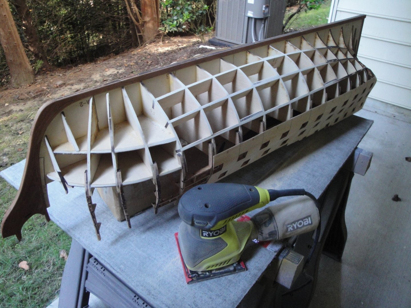
I know I am going to shock a few members, but I started sanding the bottom of the hull with an electric sander and 60 grit paper: Honestly, unless you want to exhaust yourself and loose your arms, that is the only way to do it. We are dealing with very good 5 plies plywood, almost marine quality and it is quite hard to sand. This is not the basswood found in Model Shipways kit (nothing wrong with their kits, by the way). After one hour on each side, I am getting a smoother hull: Below you can see one side almost done and the other side still untouched. I will finish the stern by hand and more delicately. WOW, I did produce an enormous amount of dust and this is the kid of work that needs to be done outside. With the hull mostly sanded and smooth, I can now address the stern which is the most exciting part on such vessels. Yves

- 507 replies
-
- 21
-
-
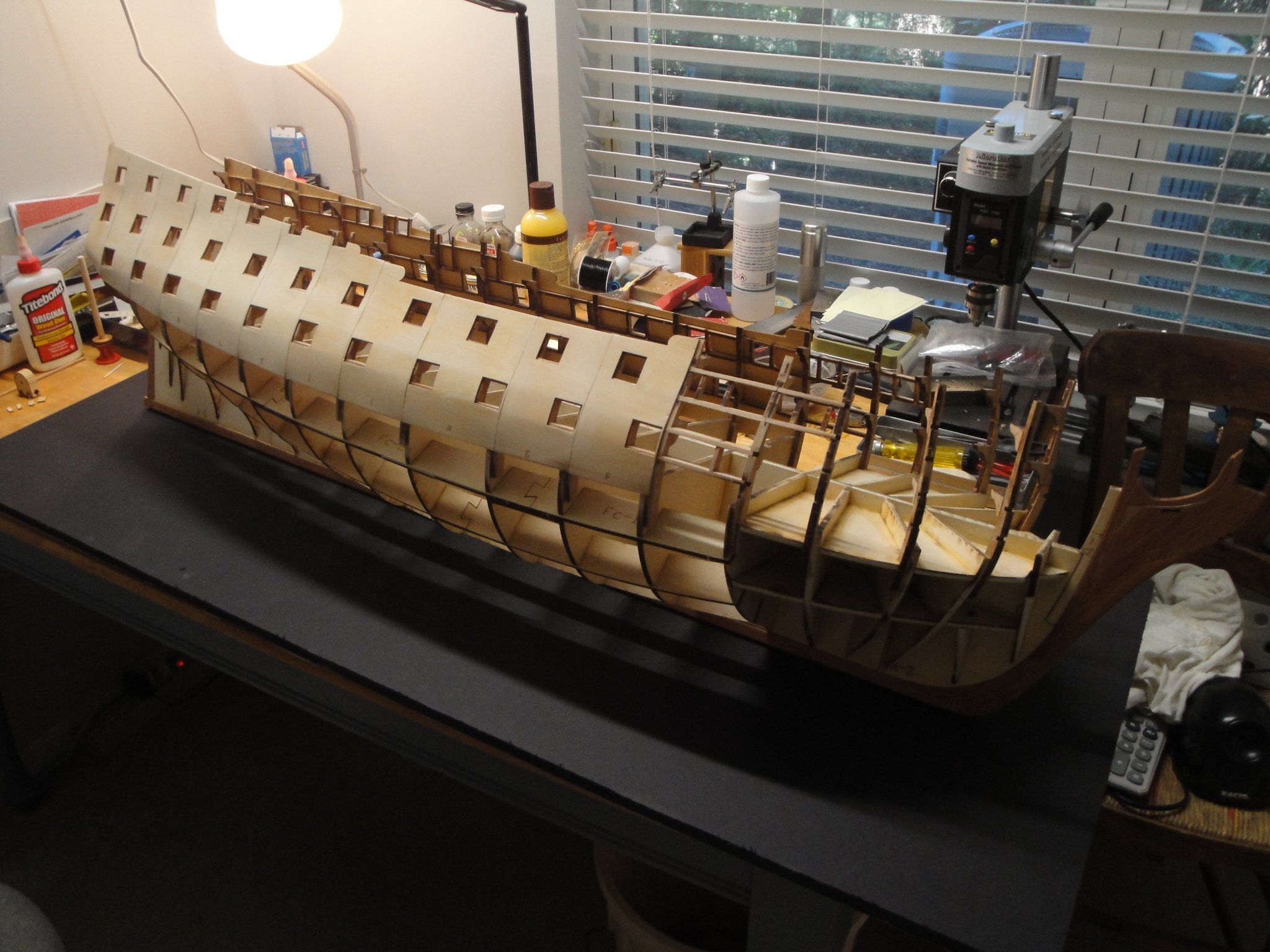
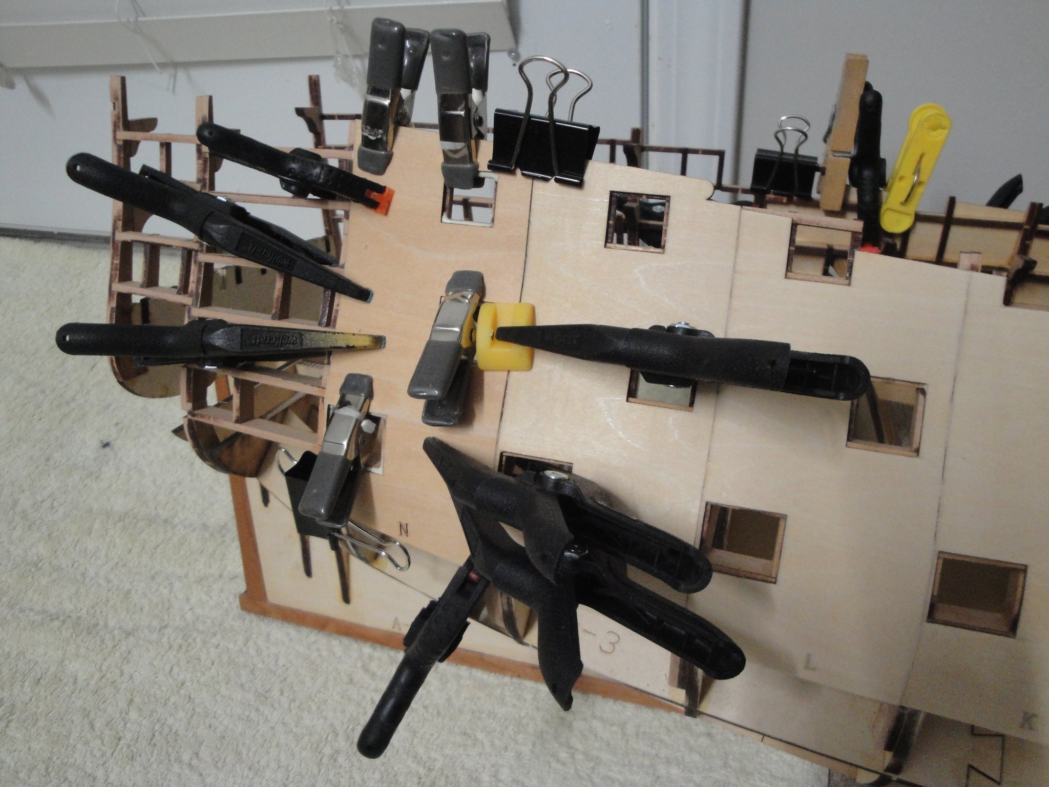
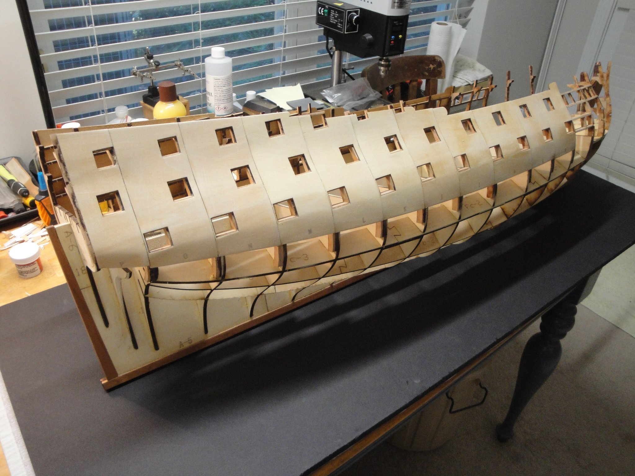
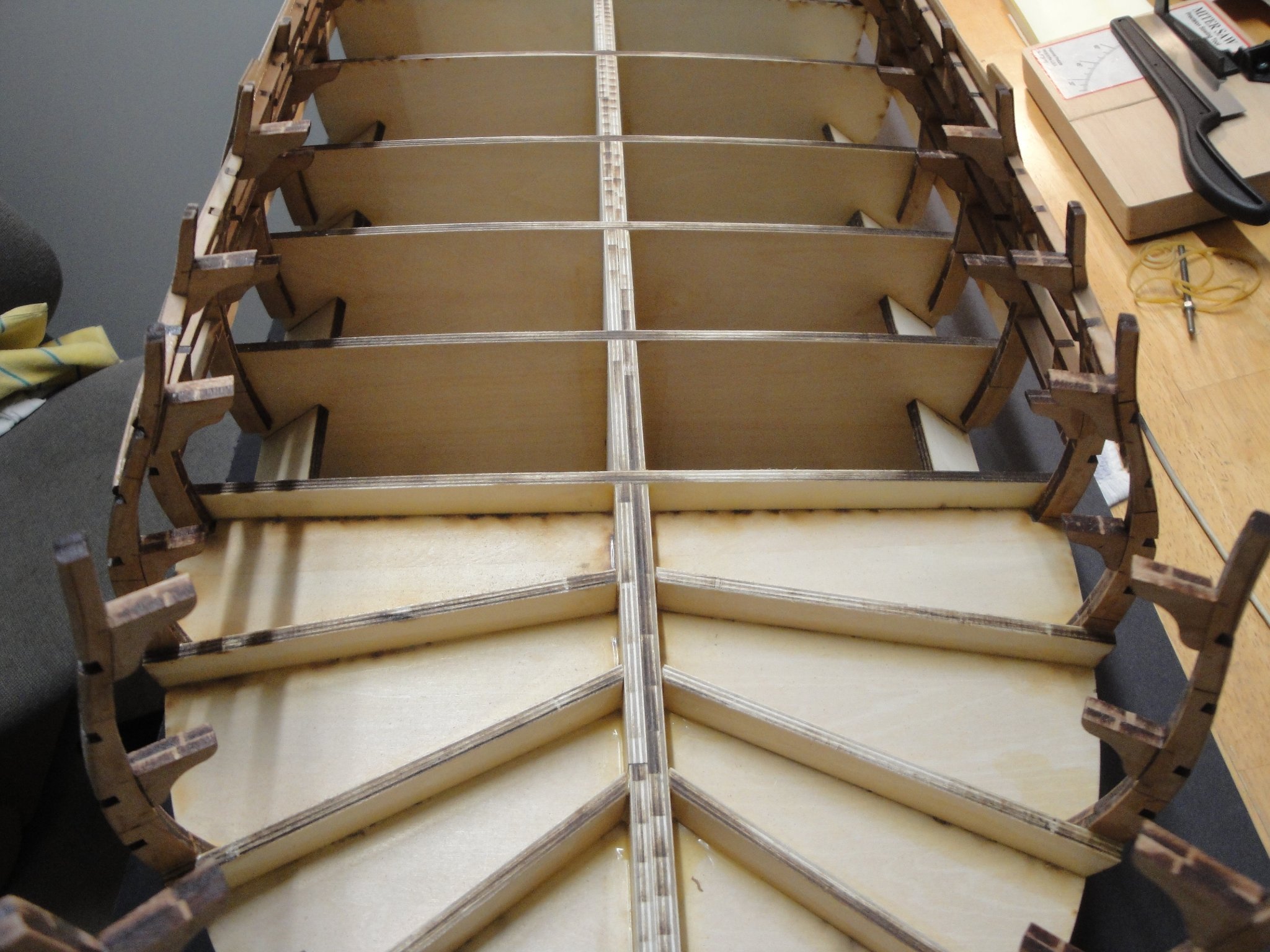
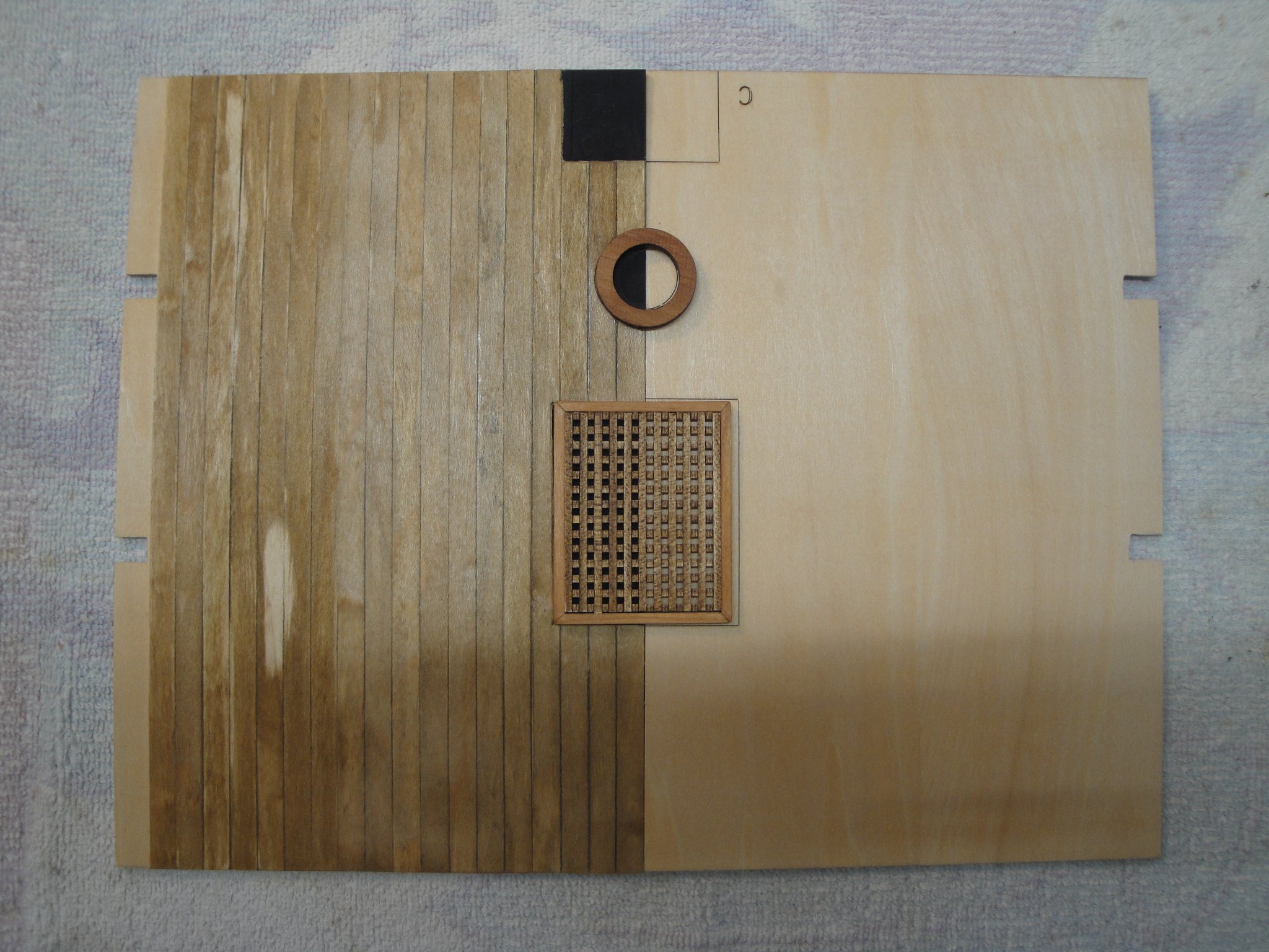
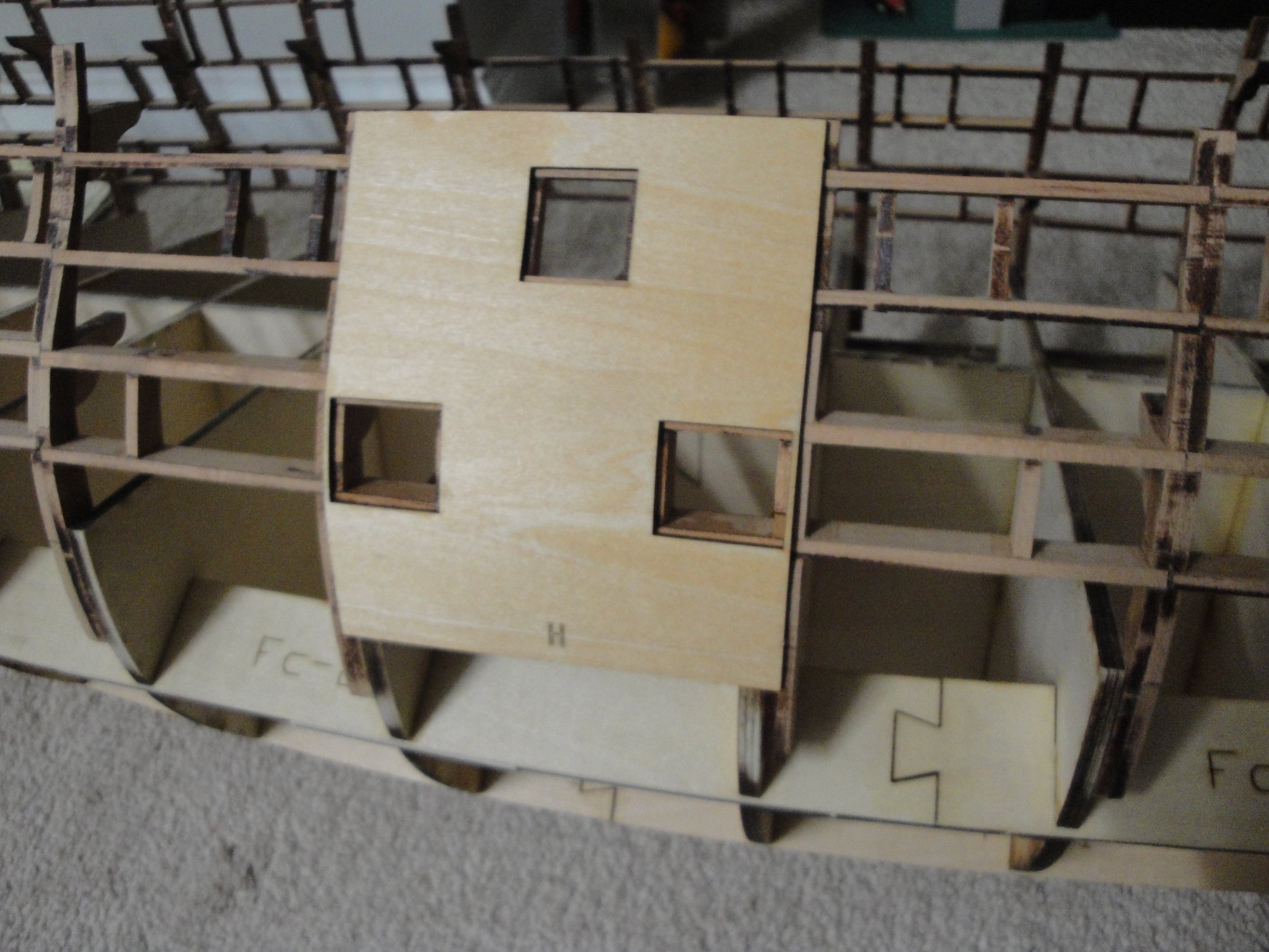
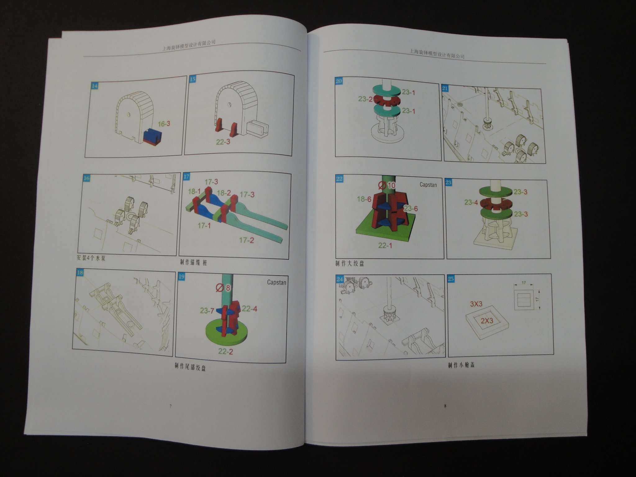
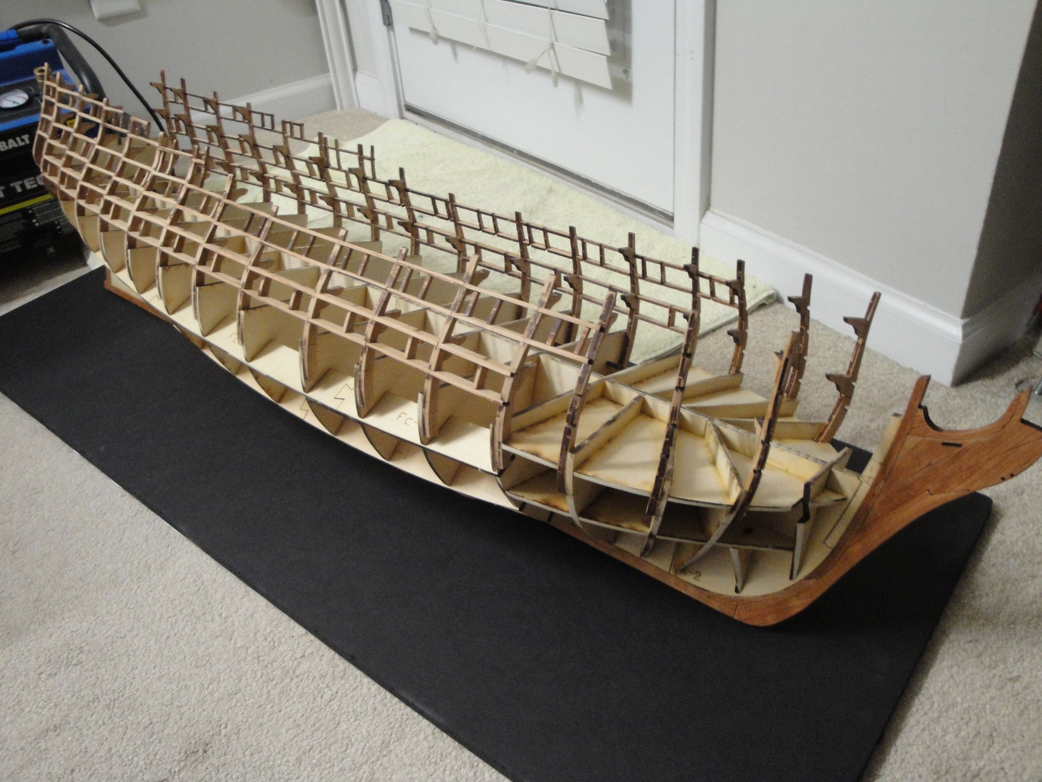
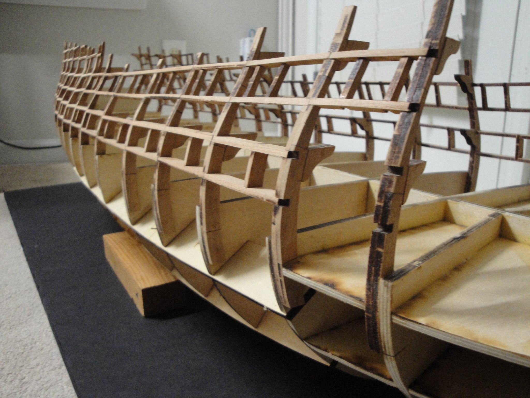
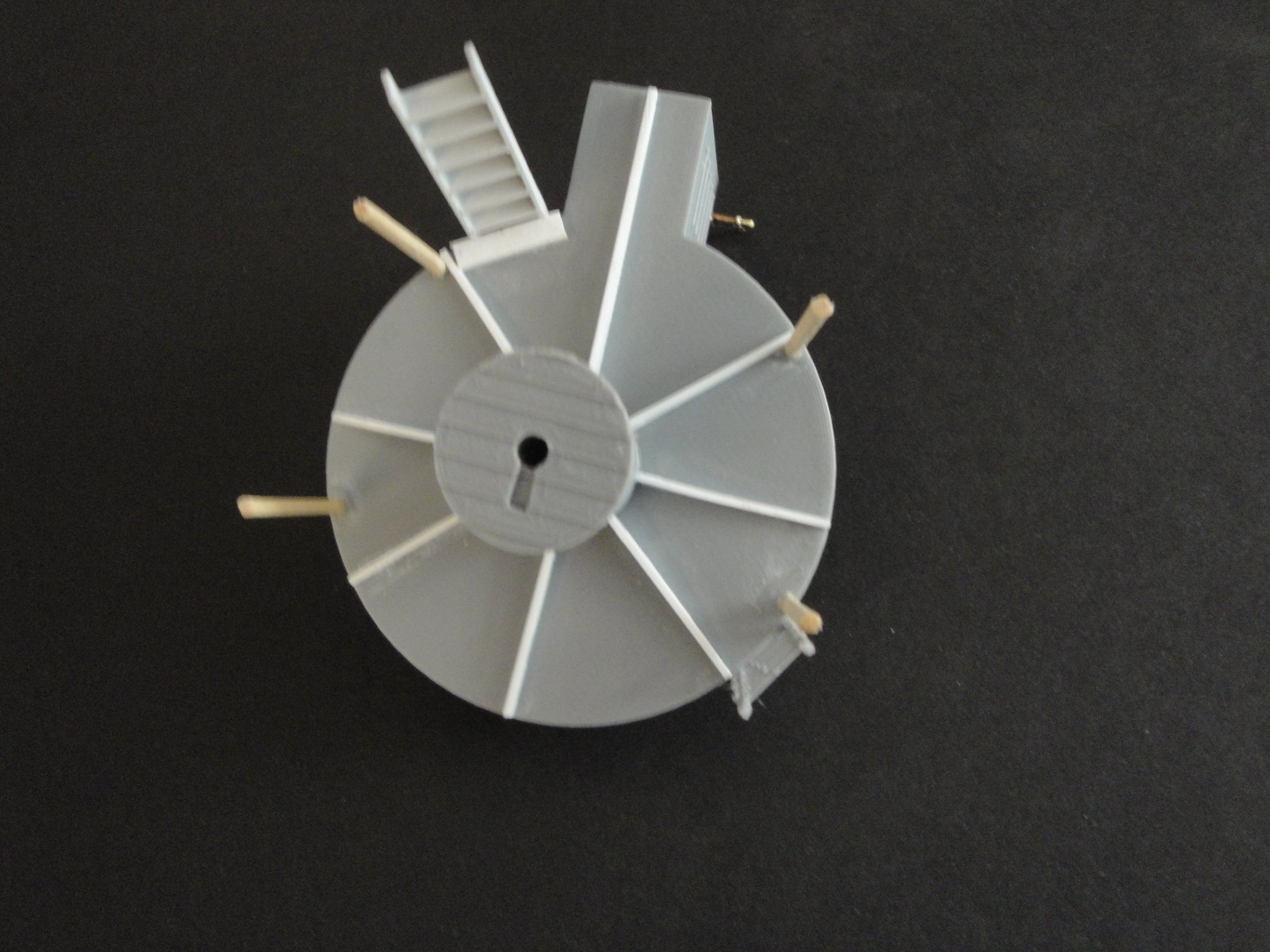
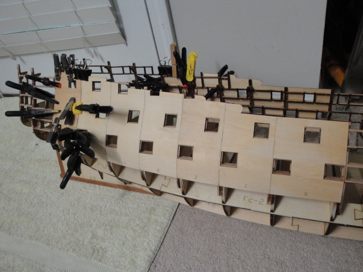
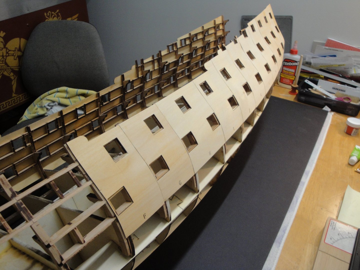
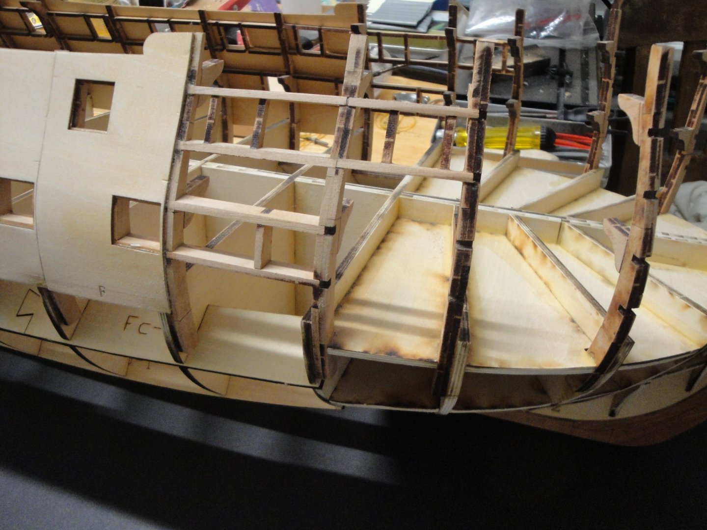
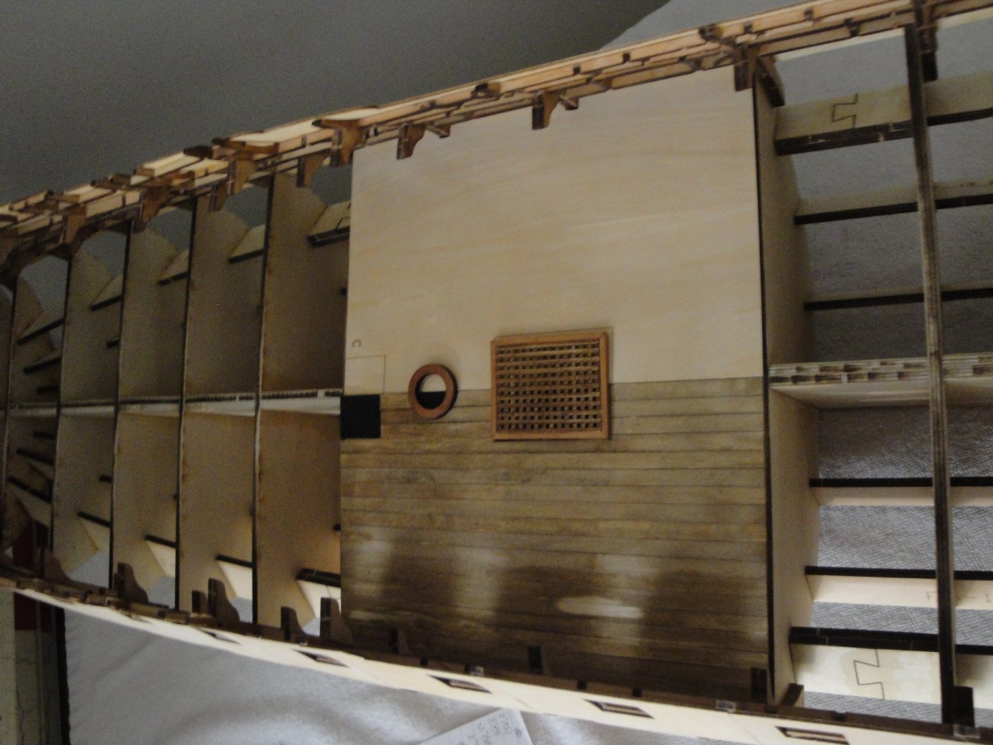
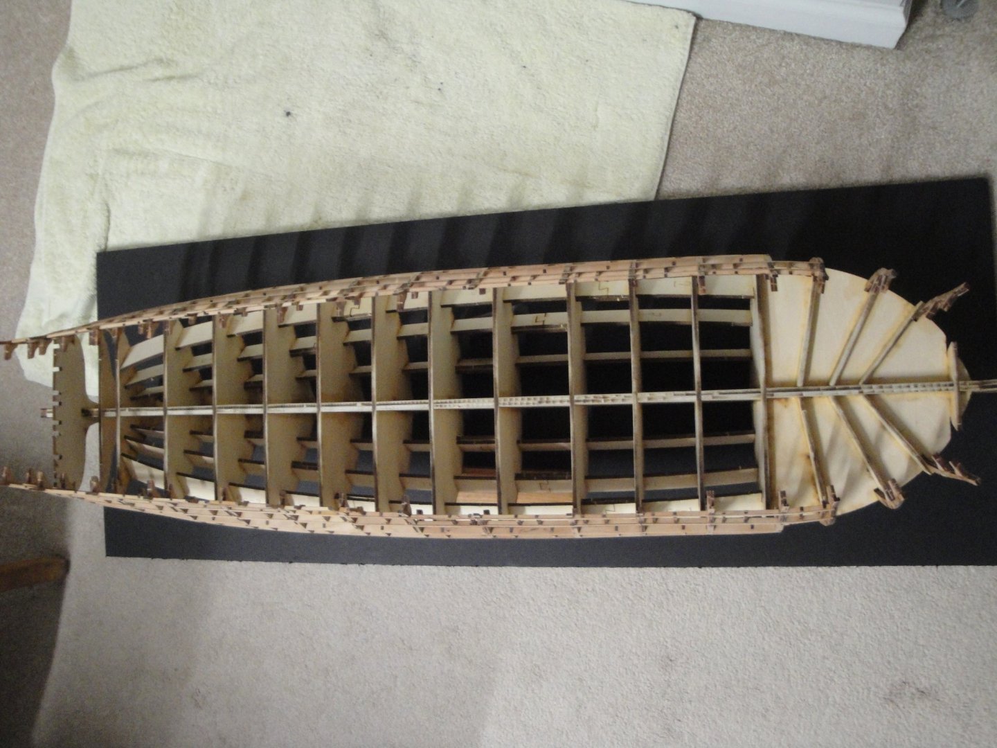
A quick update, as I am moving on with Session #2 - Session #1 remaining unfinished for the time being (Stem and Stern). Using the thin plywood (1.5 mm) provided in Session #2, the shell is build around the vessel, in preparation for the planking and the wales: Each plate takes about 4 to 5 hours to fully dry, using Titebond glue. The hour-glass shape of the hull requires a lot of fasteners to marry the shape of the futtocks: The overall result is rather pleasant with a very smooth hull sides. There may be a couple of places where some putty will be needed to compensate for a low spot, but overall, the precision of the cuts and quality of the wood is amazing, on such large vessel. The Stem is still in waiting mode as I need to most likely deconstruct Futtocks #4 and reposition them to get a smoother flow of the hull: Futtock #4 is the dark frame which has not been sanded yet (see above). You may be able to see that frame #4 is too narrow (see above). This is really my only complaint about Session #1 in this kit: the lack of guidance and proper alignment of the frames at the top of the futtocks. How will the Forecastle deck fit (session #3) if these frames are not properly spaced ? Below is an overall view: For a change of pace, I have decided to start working on the main gun deck. It is made up of 10 large halves, built with a very nice plywood of 2 mm. The gun deck is part of Session #2 and most of it will be entirely covered by the Upper deck, Quarter Deck and Forecastle deck on top. Planking is done for fun and there is no need to stagger the planks since nothing will be visible through the ports occupied by the muzzle of 32 pounds gun. Planking is done with Maple of 0.4 mm thick. The difference in color comes from the fact that the left planks were recently stained and the wood has not had the time to absorb the color. The ring is the base for the main mast. Around the mast will be located four bilge pumps. In situ, below: Not much can be seen.... Yves


- 507 replies
-
- 17
-
-

-
The so called "prototype build" is turning into a very nice model !! Yves
-
That is a gorgeous boat Ryland. I just got the same kit from Model Shipways and plan to place it on the deck of the Bellona, if I ever get there one day.... Yves
-
Building scale ship models is a school of patience. You spend more time waiting for parts than building the model itself.... Yves
- 127 replies
-
- 3
-
-
-
- Bowdoin
- Arctic Exploration
- (and 3 more)
-
What an ambitious project. It is amazing and you are mastering all techniques in this build: 3D scale modelling, large model building, mechanical, electrical and artistic. I will follow your build with a lot of interest. Yves
- 454 replies
-
- 1
-
-
- Union Steamship Company
- Stepcraft 840
- (and 3 more)
-
What a beautiful interior.... Very realistic. You need a cat and a few rats, in there... 🙂 Yves
-
Very interesting and so unusual model. It reminds me of the little brother of the Chebec. Yves
- 35 replies
-
- 1
-
-
- Artesania Latina
- Sultan
- (and 1 more)
-
Interesting choice. The Russian Navy had a lot of very unusual vessels and I am so glad that these models are coming to the Western world, finally. Yves
-
Kevin, I have been following your Enterprise kit and was seduced by what CAF is offering. The Bellona is a little simpler since it is Plank on Bulkheads and it has a reduced and simplified interior. It compensates in size, though..... If I ever manage to do something decent with Bellona, I'd like to do the Chebec from CAF one day. I have always been in love with those sleek and fast ships. Yves
-
Craig, another master piece in the making.... WOW, you sure are aligning those 1/700 scale ships at great speed. I wish Trumpeter would produce a 1/200 version of that same monster, to replace the old and so incorrect Nichimo kit. Yves
-
You should not paint the tire of the wheels. If I may offer an opinion, the wheels were not painted black: they are naturally rusting, so a brown rust is more appropriate. Secondly, the tire is always shinny since the car running on these section of the wheels, rust cannot adhere. I would use some paint thinner and clean the outside of your wheels. If you ever run them on a small piece of track, they will look awful, once the paint starts peeling. Yves
-
What an heresy. You will have so much pleasure rolling it back and forth on the short track that is provided. And who knows, that may be the beginning of a huge layout in your basement or garden..... Yves
-
They truly put a lot of brass in that kit..... Very colorful !! Yves
- 273 replies
-
- 3
-
-
- panart
- amerigo vespucci
- (and 1 more)
-
I will think about the display later on 🙂 For the time being I enjoy the building process. I wish there was some kind of small Museum (open to the public) in the area, where people can display what they build. That model and others would definitely be perfect in such a place..... I have the same dilemma with my large Flower Class Corvette..... Yves
-
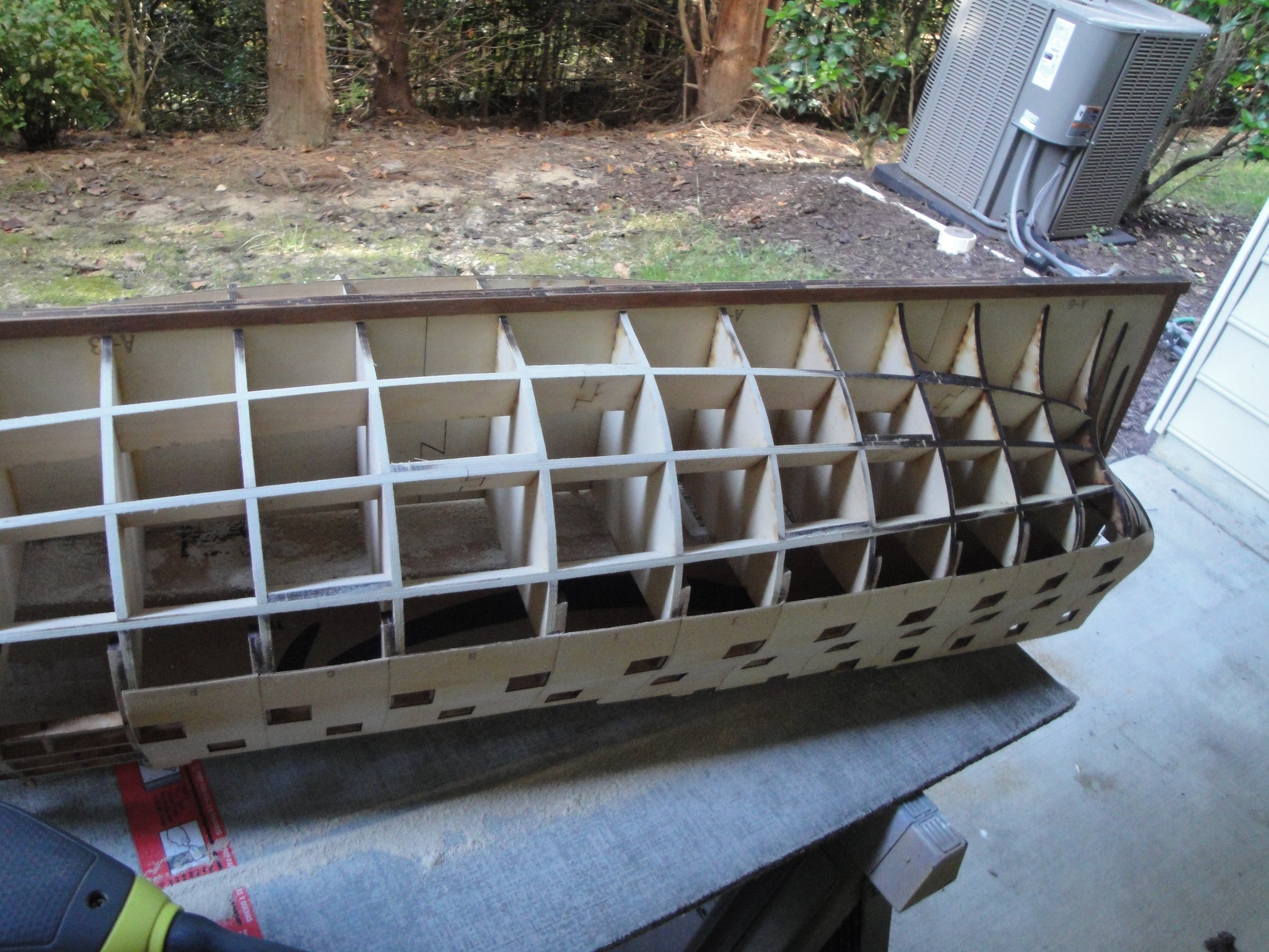
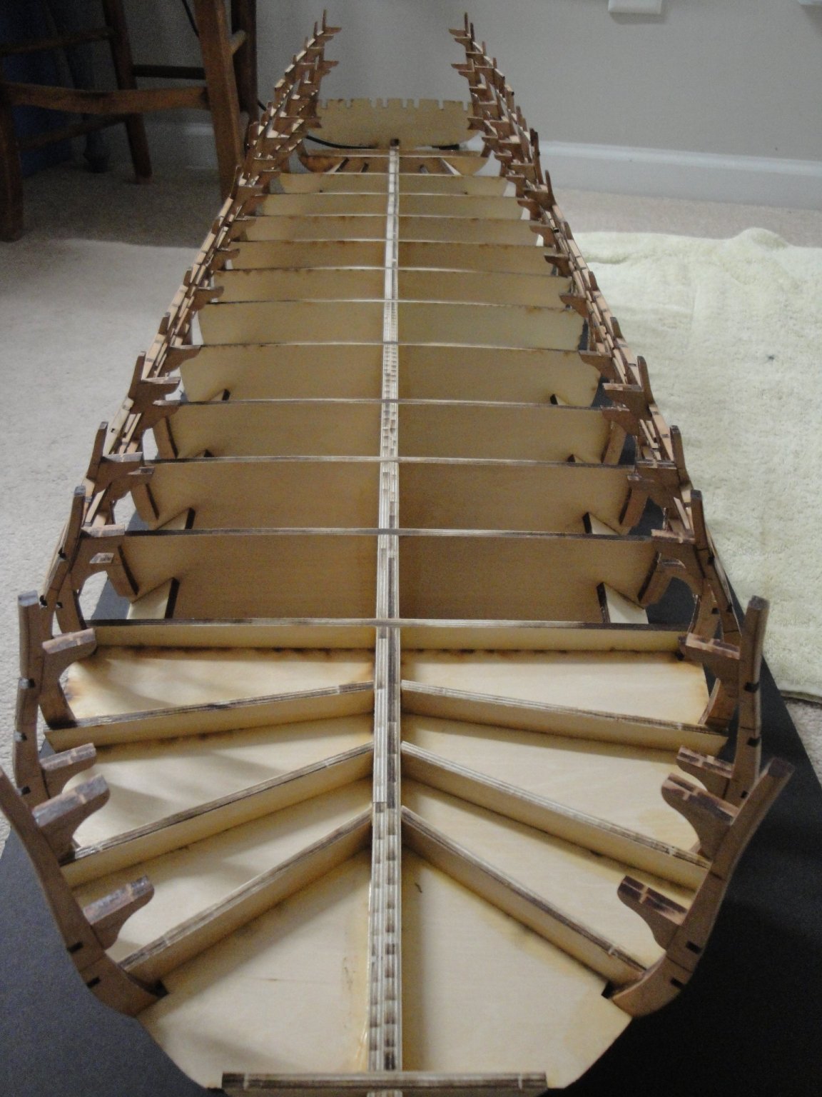
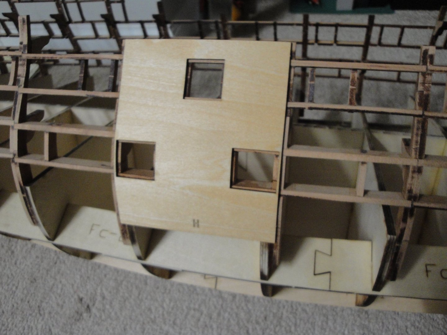
So, without waiting and to verify the parts of Session #2, I could not help myself and started gluing the central shell piece: The fitting is beautiful and the cuts are perfect. The shell pieces are cut in a 1.5 mm thick plywood, which do marry tenderly the curves of the futtocks. Once completed, this should give us a very nice and solid hull, for planking. Yves
- 507 replies
-
- 19
-
-
-
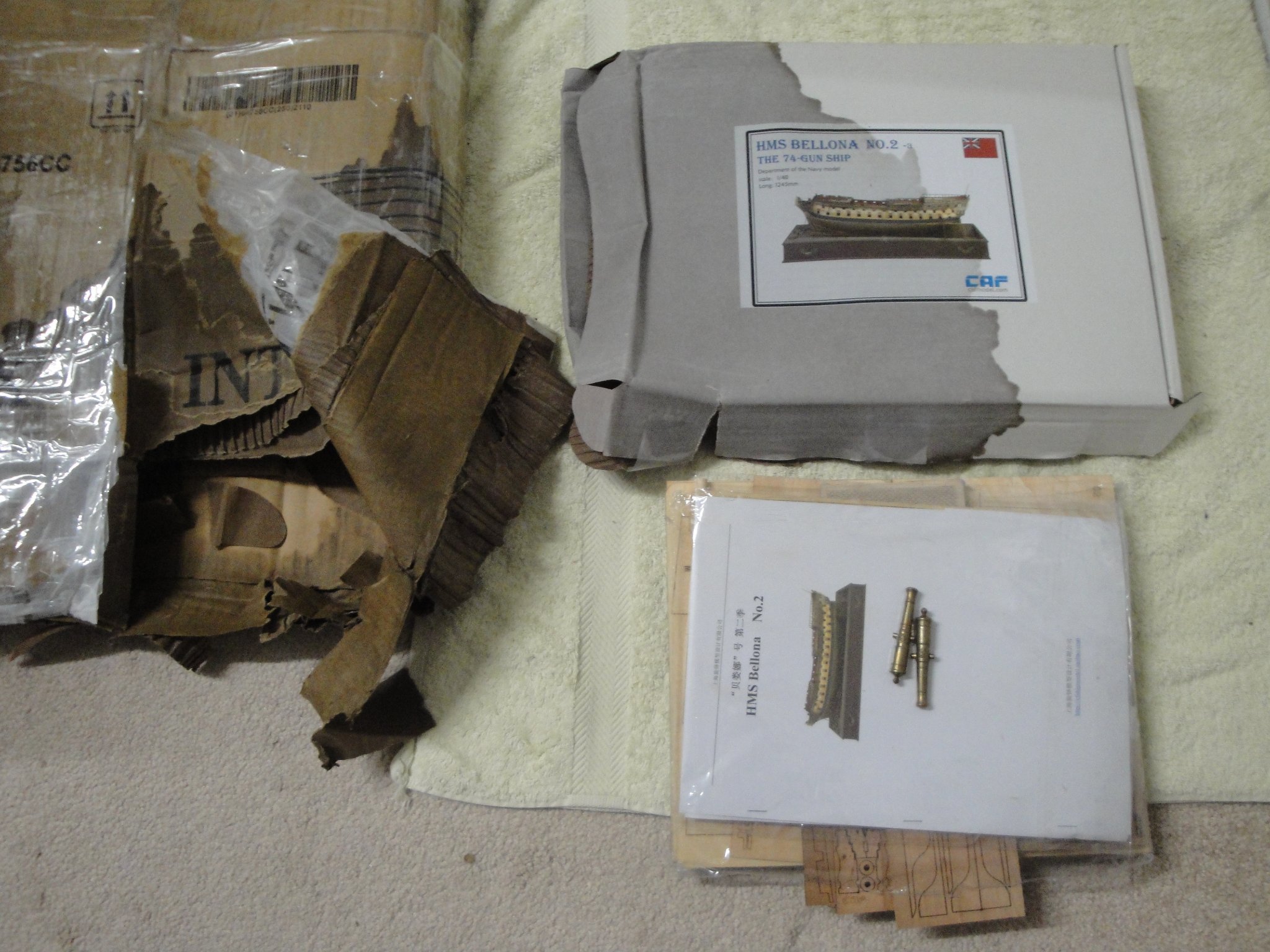
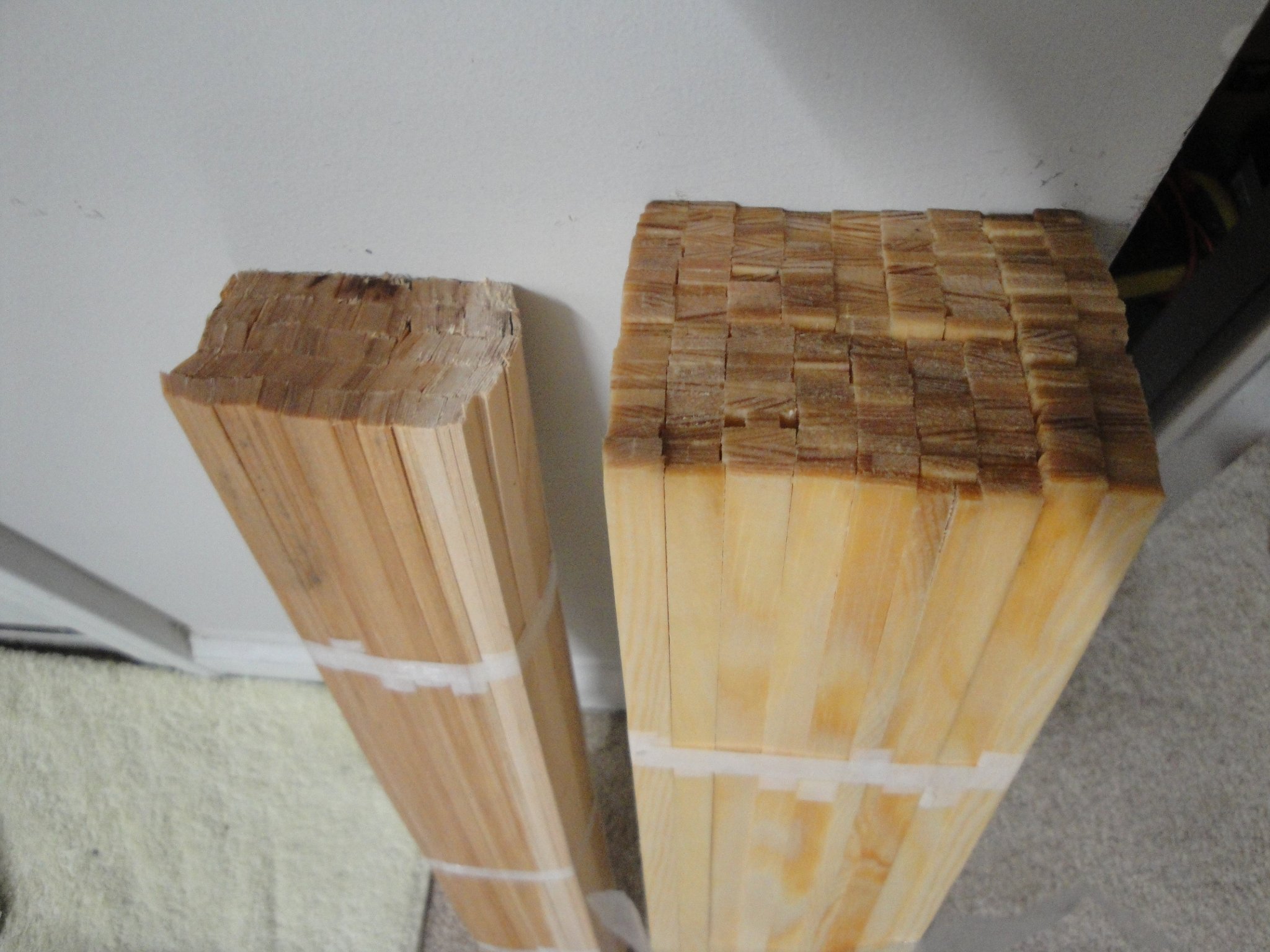
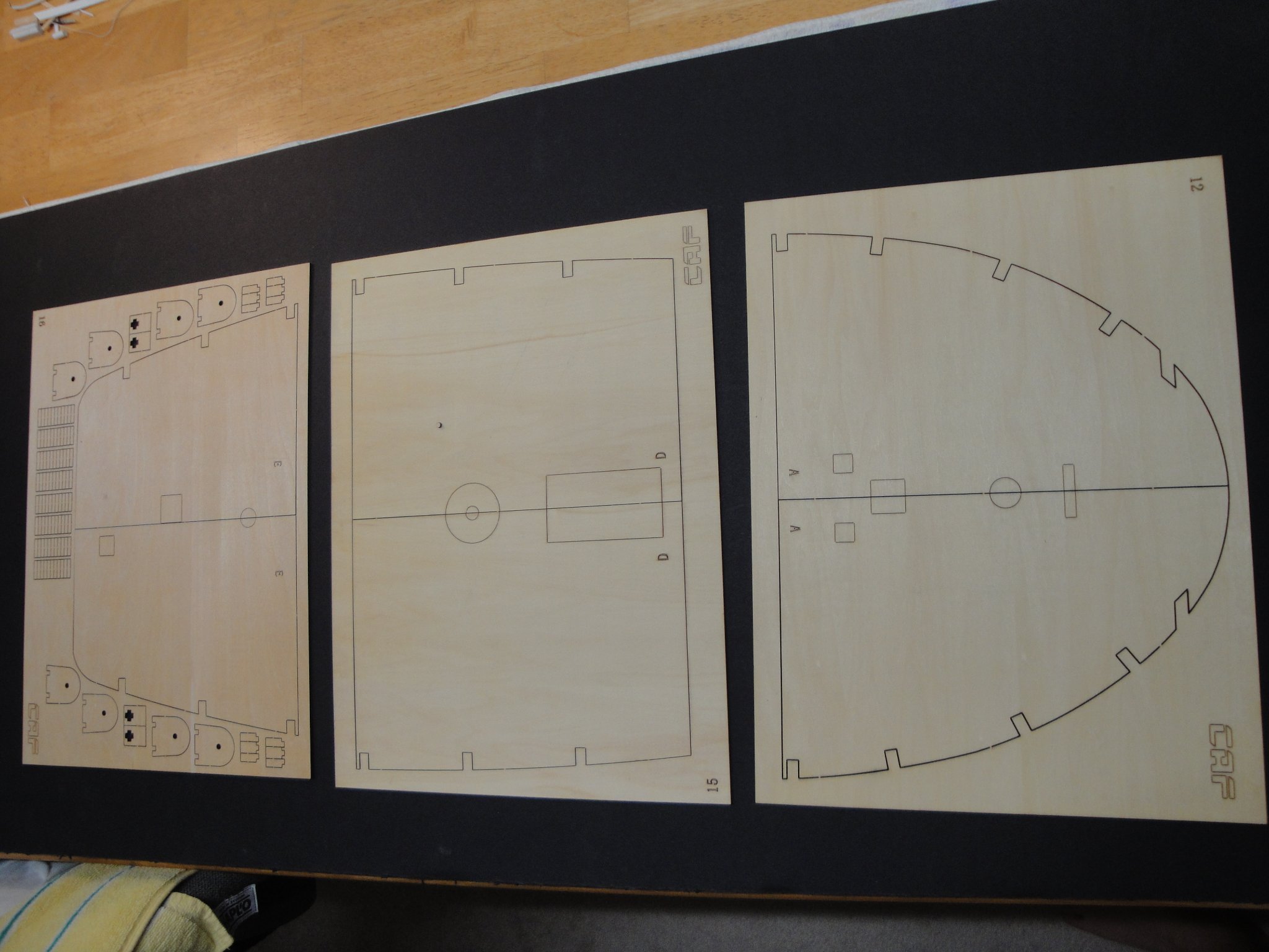
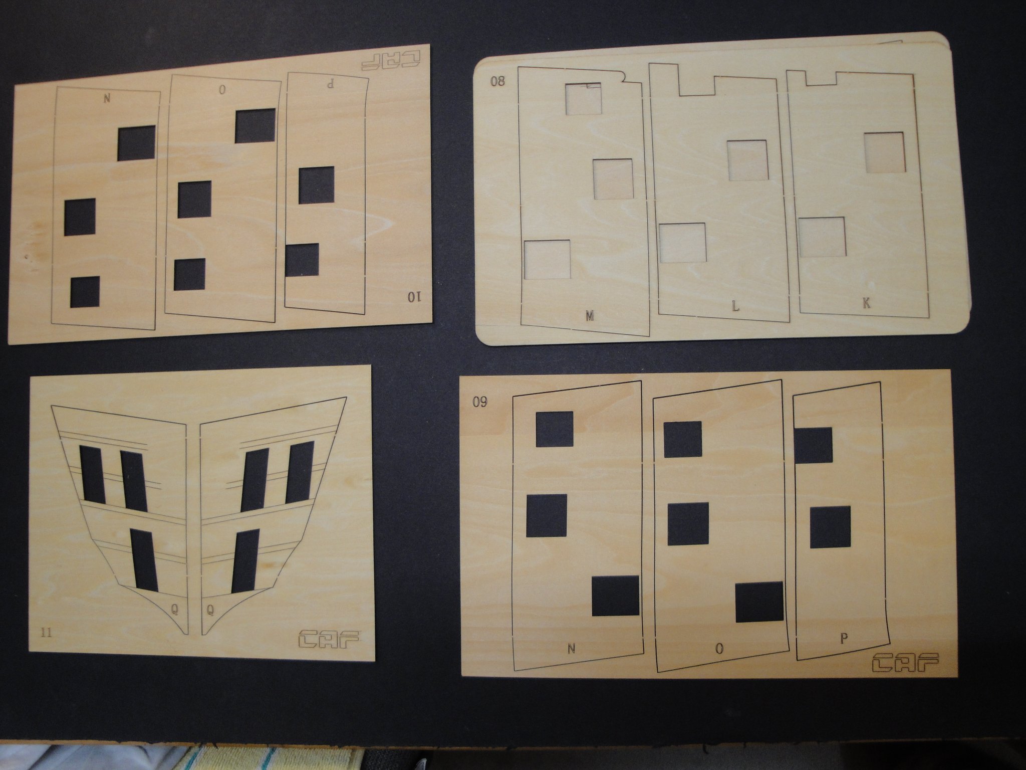
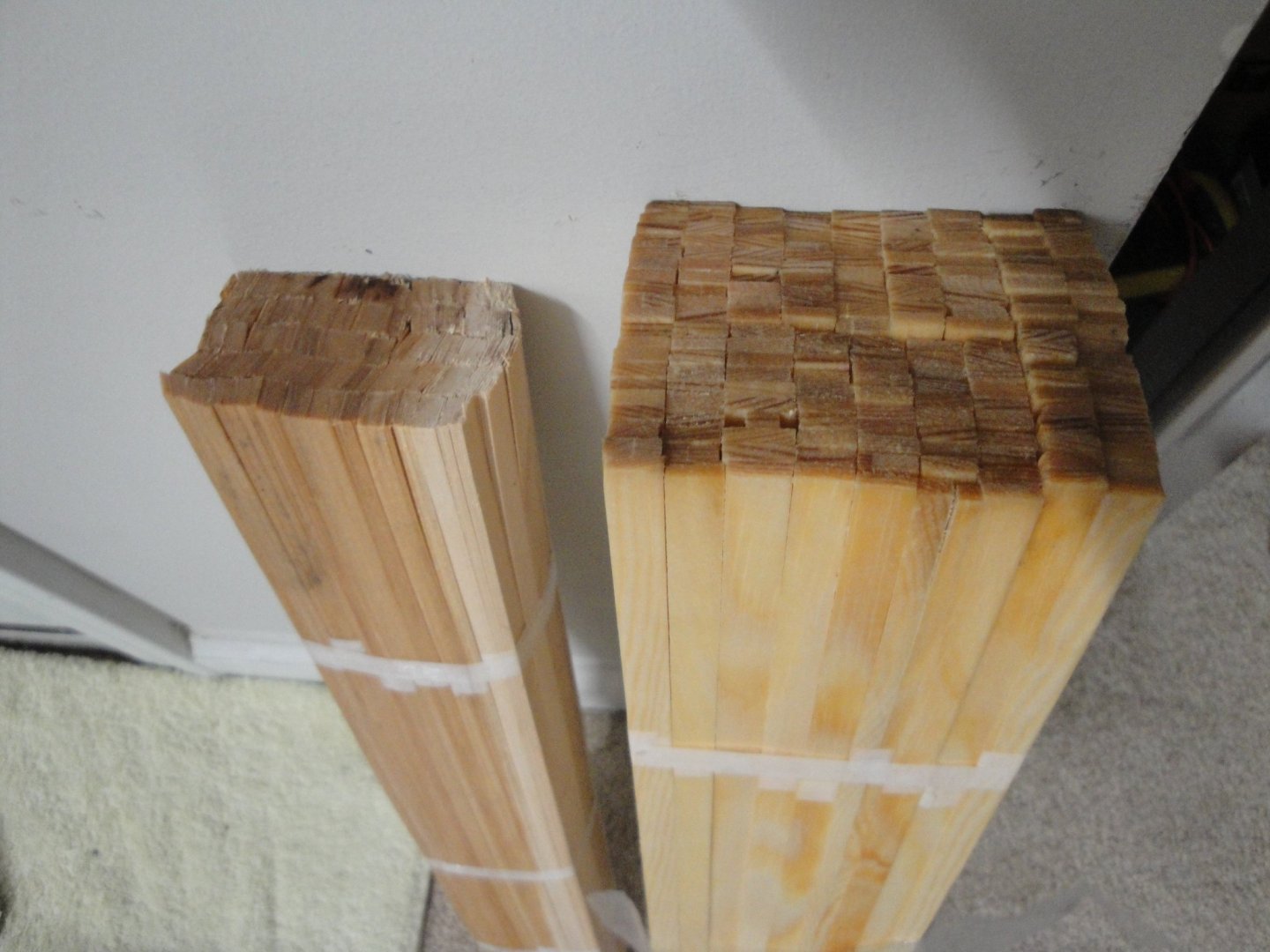
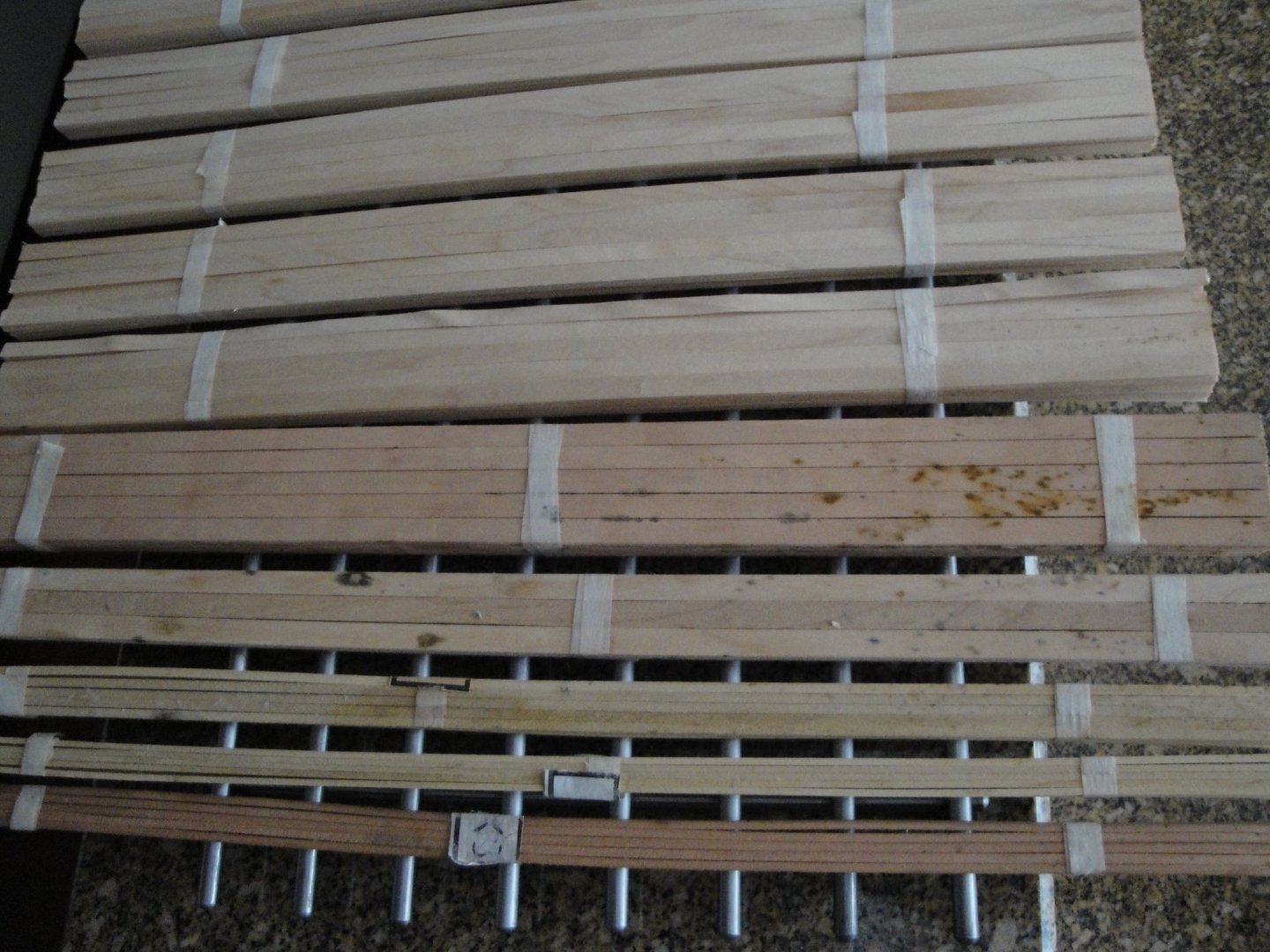
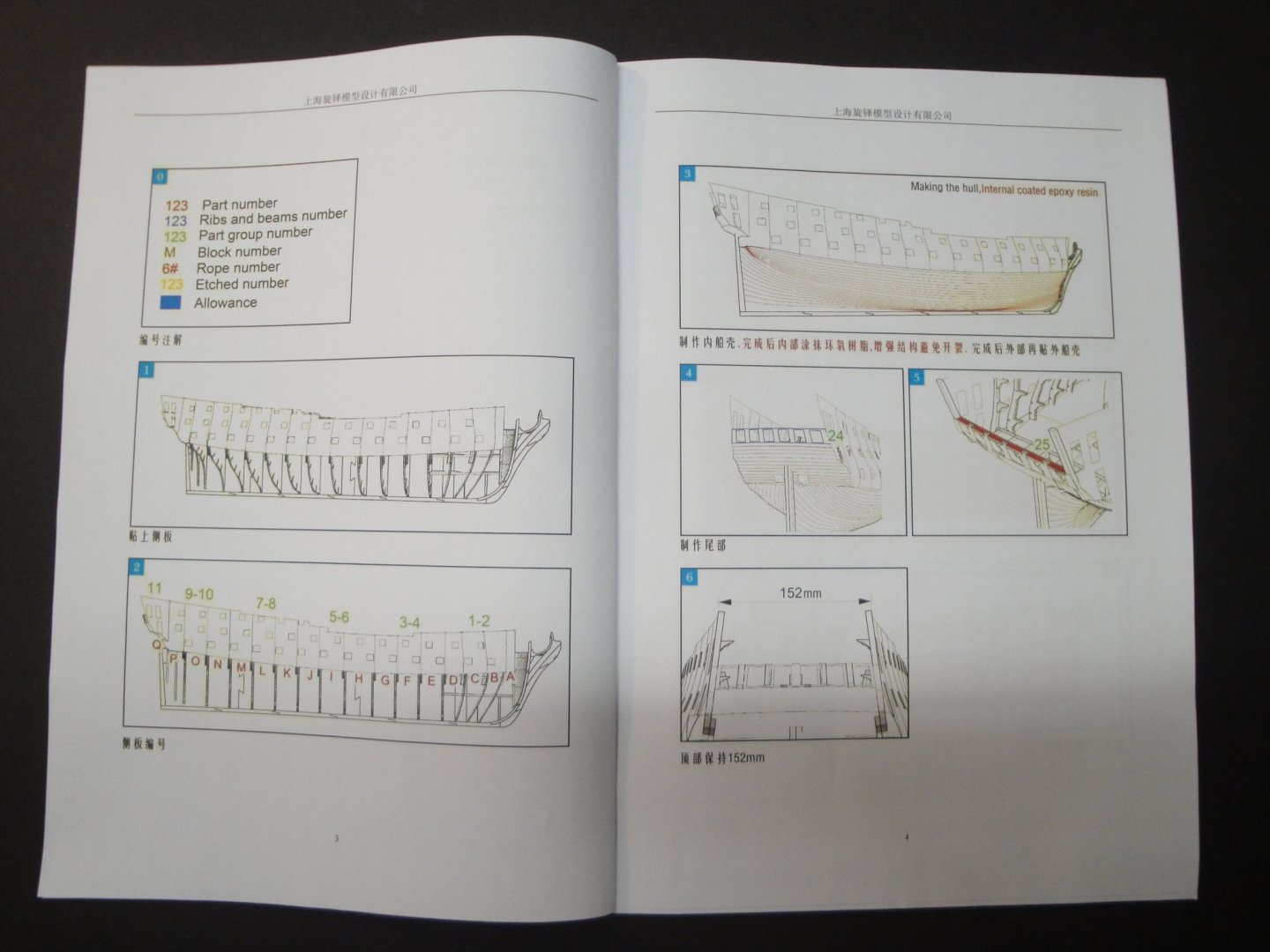
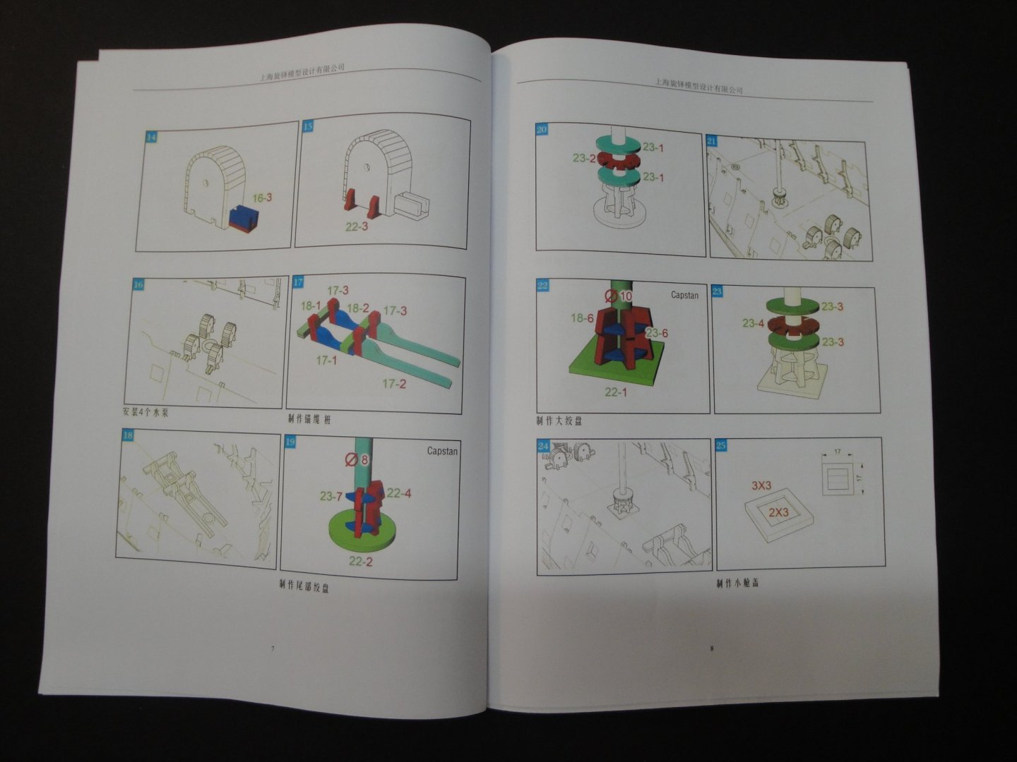
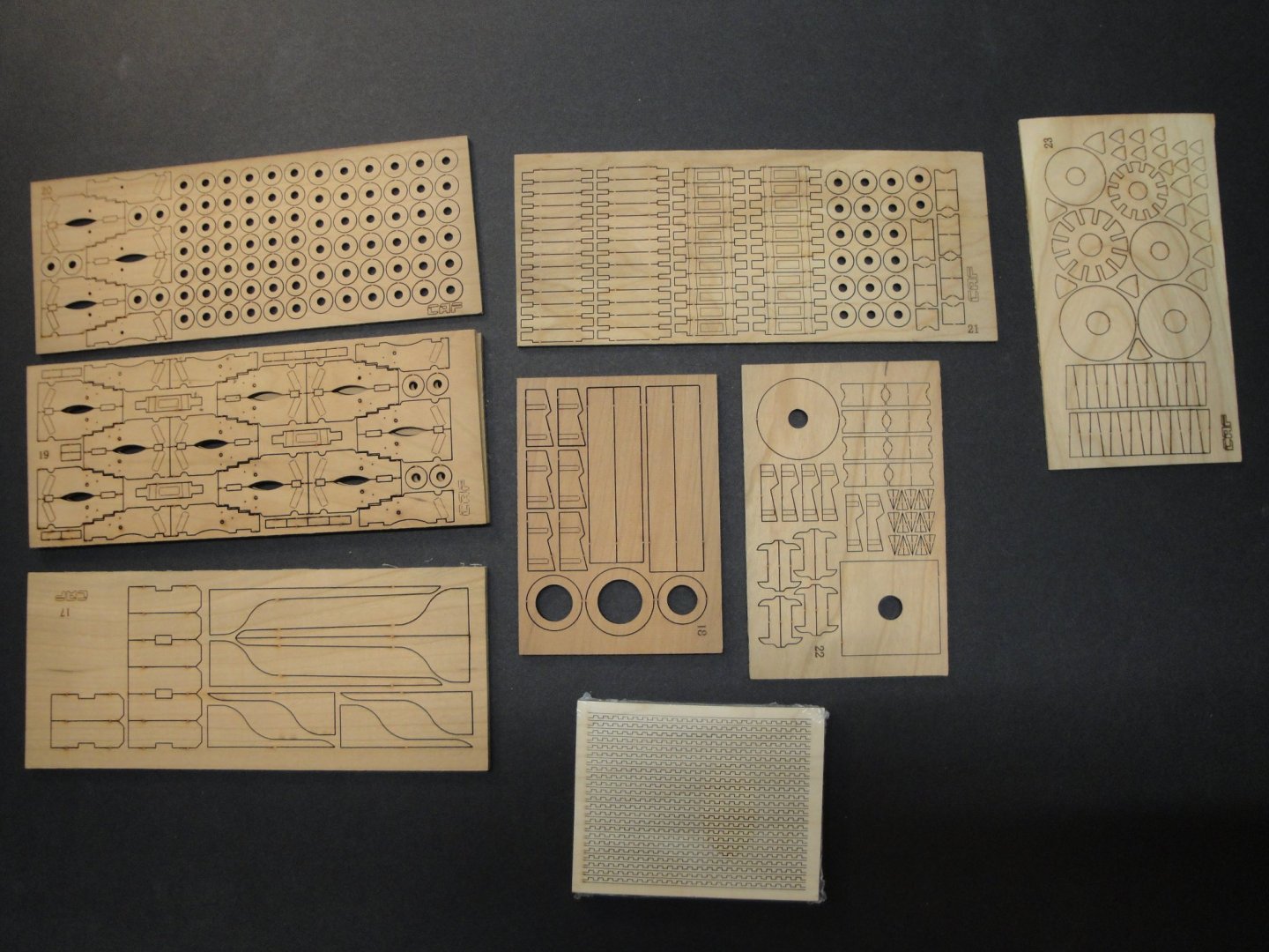
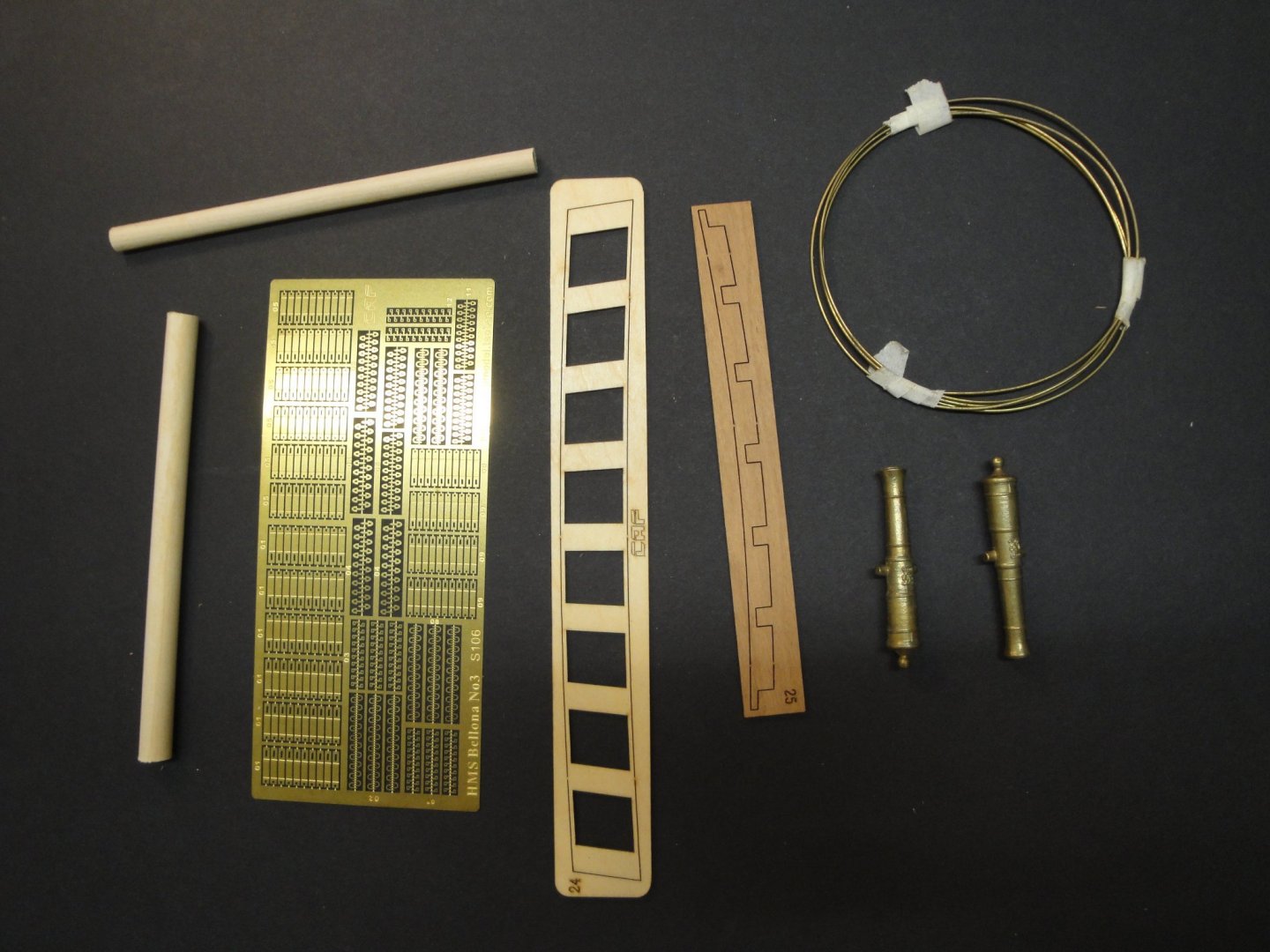
- SESSION #2 - Before finishing Session #1 completely, I had to have parts from Session #2 and ideally from Session #3. We will get into the details later. Session #2 package was ordered directly from CAF model in Shanghai, apparently. The parcel took close to two weeks to arrive and was severely damaged by water. As you may not know, a lot of China is under the water due to weather manipulations and enormous rains, and people are suffering a lot. My parcel was probably flooded in Shanghai and kept its humidity long enough to develop some mildew.... Session #2 is about $250 plus shipping. Fortunately, the content of the kit Session #2 itself, was not damaged by the water since it was protected by a film. On the other hand, all the strips of wood for planking hull and deck soaked all the moisture they could. I have been trying to dry all of them in the best possible way, but a lot will have to be replaced by CAF. I have to say that their packaging was not up to their reputation and that all this disaster could have been avoided if the strips had been stored in a sealed bag. The cherry wood was prone to develop some mildew as you can see below: Tom, from CAF model, indicated that a new set of wood strips will be shipped to me (free of charge) when I purchase Session #3. I have to command his support and responsiveness. His willingness to help is a far departure from the total lack of responses from certain large European kits manufacturers for example. Anyway, despite these "aleas" of the shipping process, Tom included for me two main guns which are no longer sold with Session #2. In the past Session #2 would provide 24 main guns that will be mounted on the Gun Deck. CAF changed their approach and all the guns are now made available in Session #5 (70 guns). Let's take a look at Session #2 and what it offers. The main deck, cut on a beautiful 2 mm plywood. Again as in Session #1, we deal with beautiful material, fresh and clean wood, perfectly cut and presented. When I compare the quality of CAF parts with for instance Constructo, I am glad that I am building a kit from CAF. Documentation is again IKEA style, with not enough information.....really not enough. If we could merge the Chuck Passaro Construction guides with the quality of the CAF models, I do not know a single human being who would not be constructing these kits. And two 30 pounders main guns, finely cast in brass: Yves


- 507 replies
-
- 12
-
-
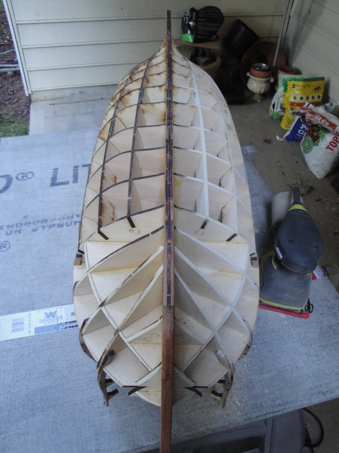
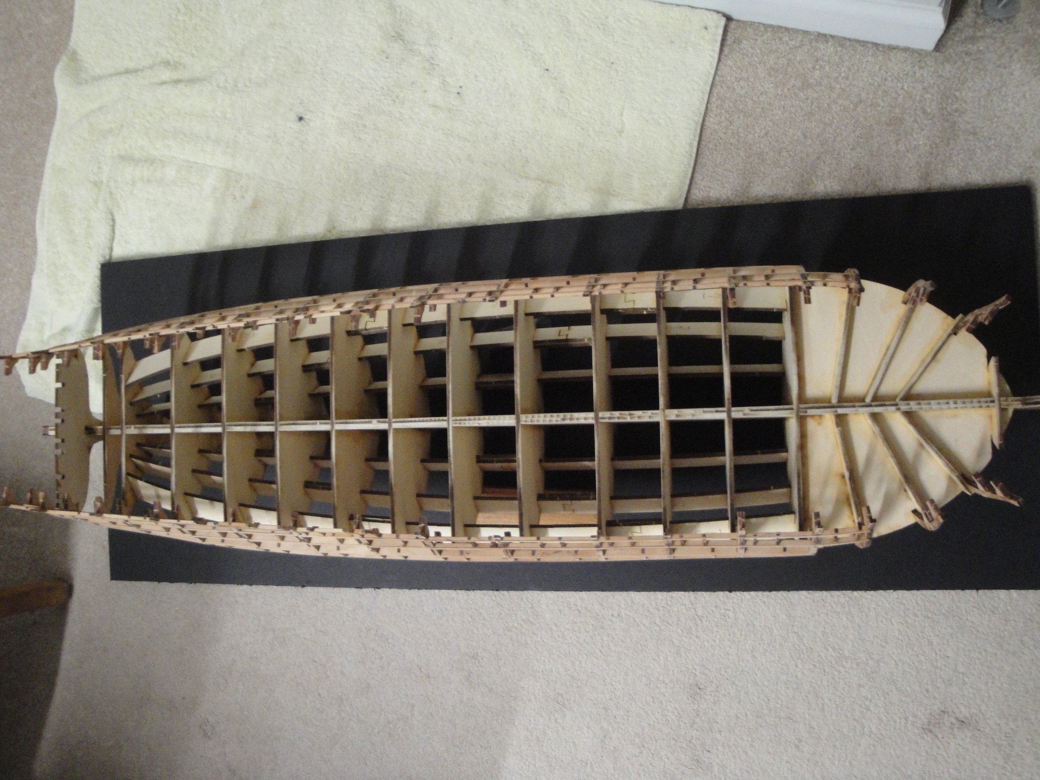
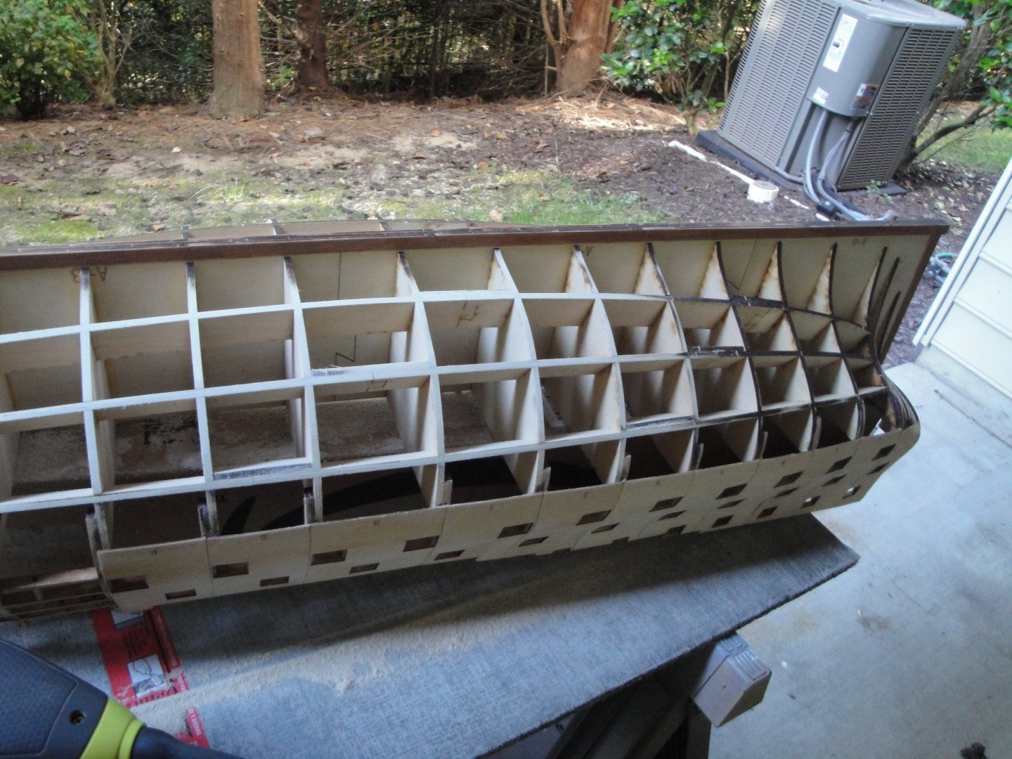
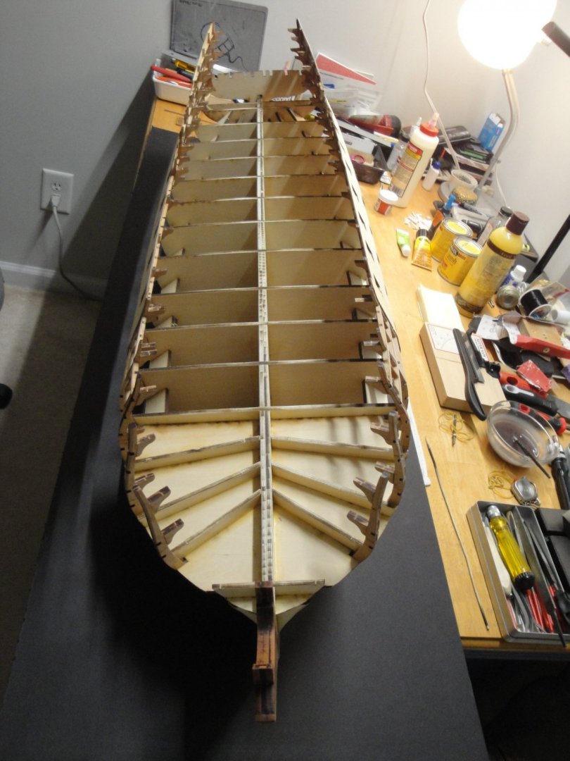
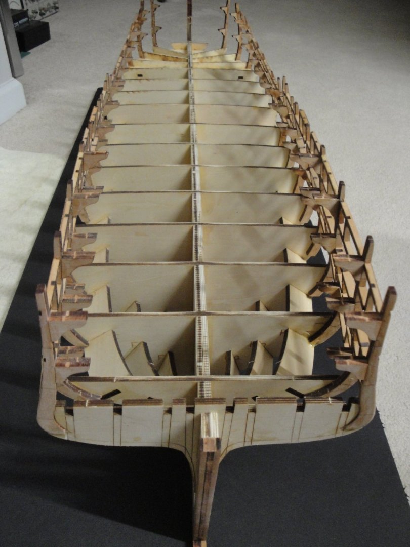
So, I have been sanding a lot recently, inhaling the fine powder of cherry wood..... As indicated, this is a massive model and quite heavy at that. The reason why the stern is not built yet, is because I am using the last bulkhead #18 for support while sanding the hull vertically. For the time being I am only sanding the futtocks, in preparation for the shells that will be glued with Session #2. The good thing with the charring is that it gives you a nice appreciation of when you have sanded enough.... The stem remains to be done and there is a lot of work there with possibly the removal of Futtocks #4 and their re-gluing. The lower portion of the hull (below the water line) is left untouched for now. I will start the sanding and smoothing of it once all the shells pieces have been glued, providing a nice protection for the delicate futtocks. Yves


- 507 replies
-
- 14
-
-
-
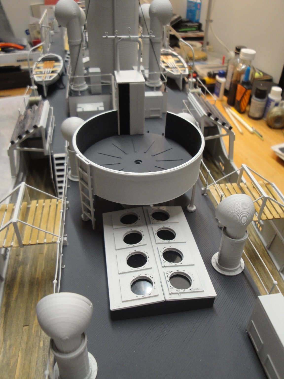
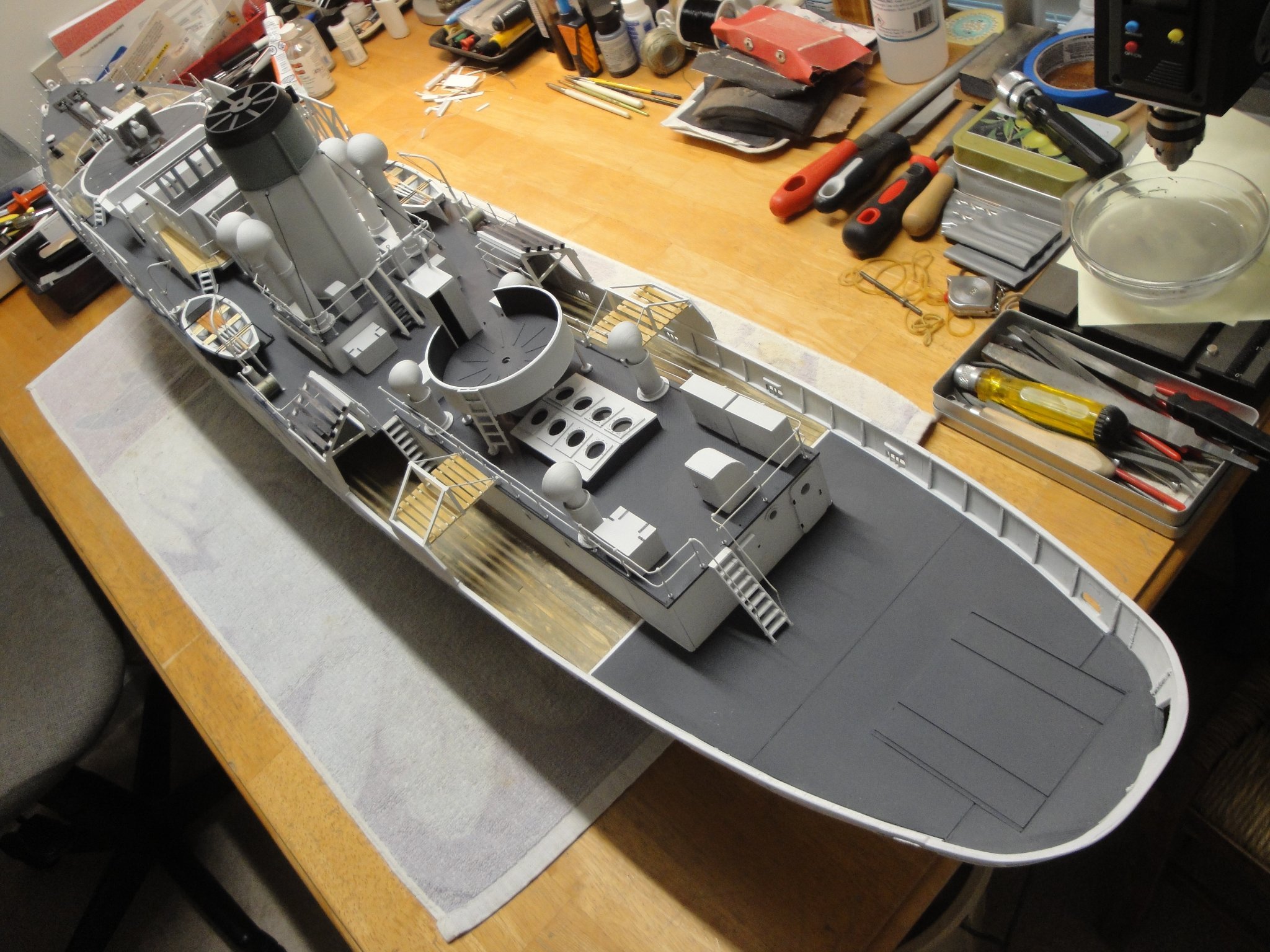
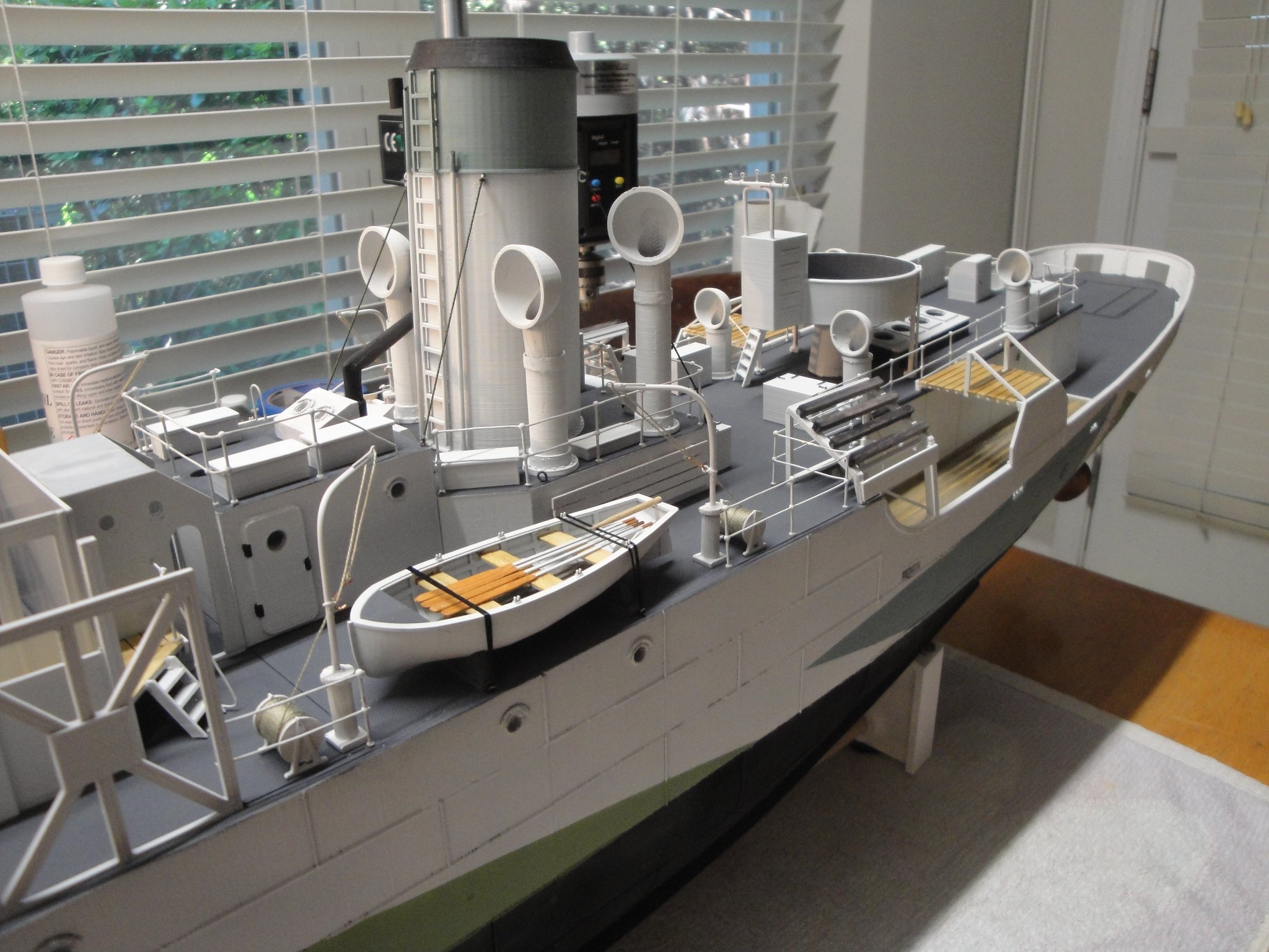
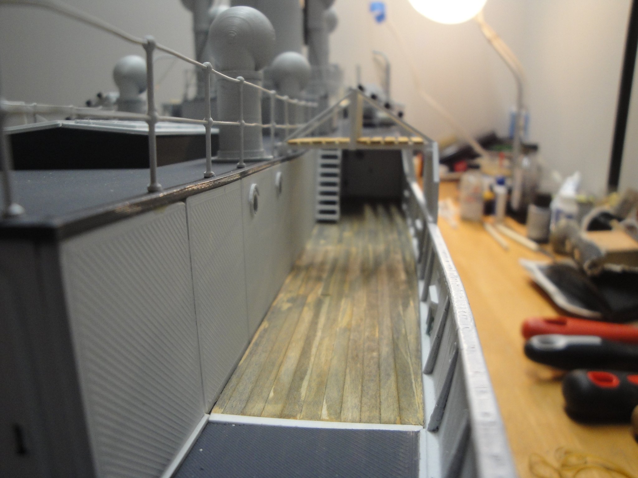
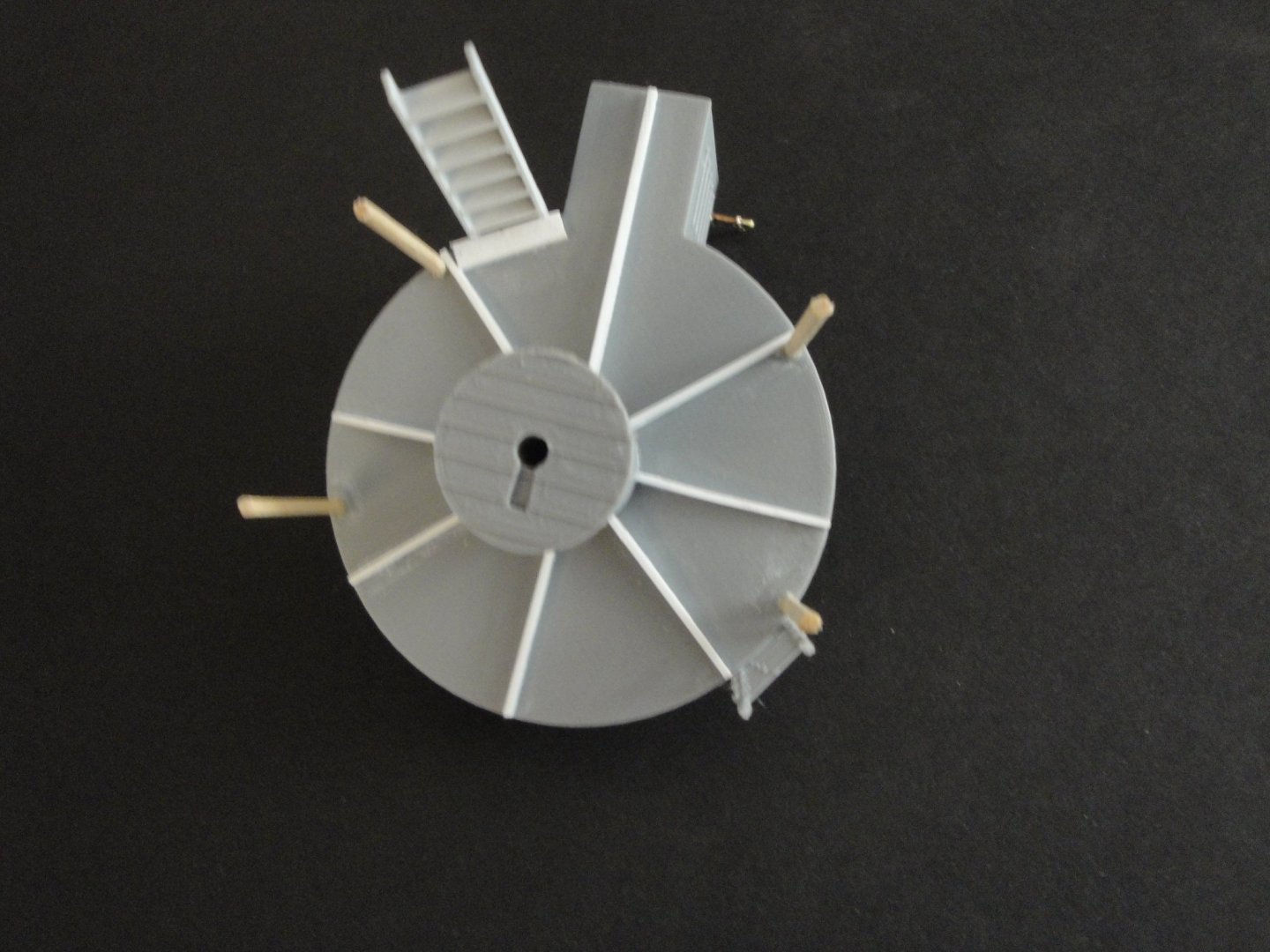
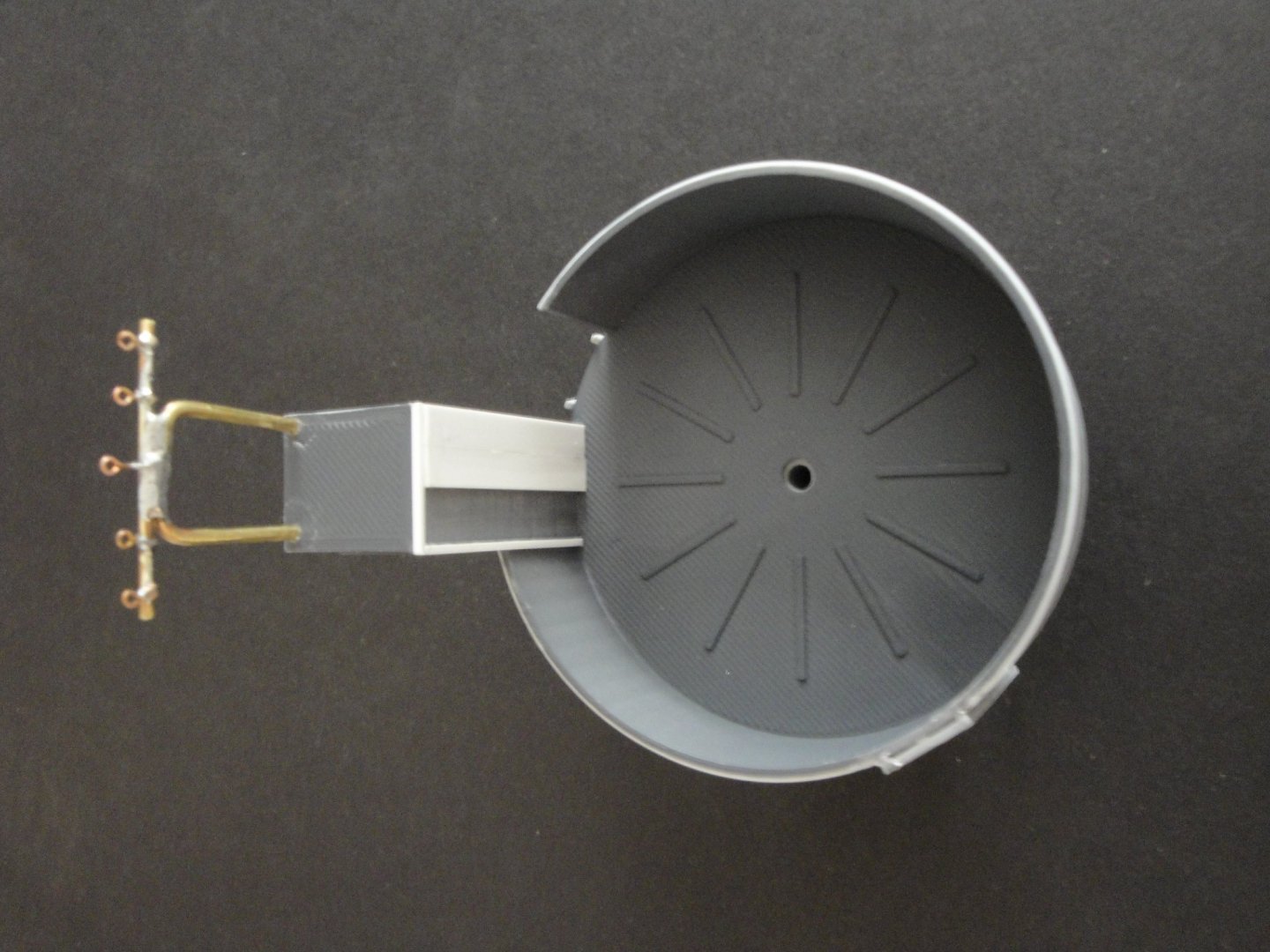
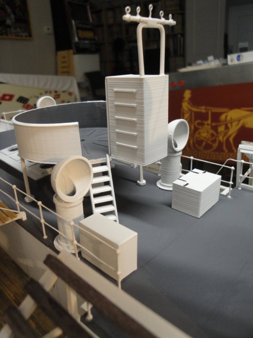
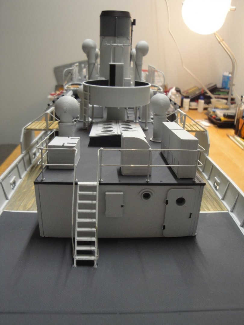
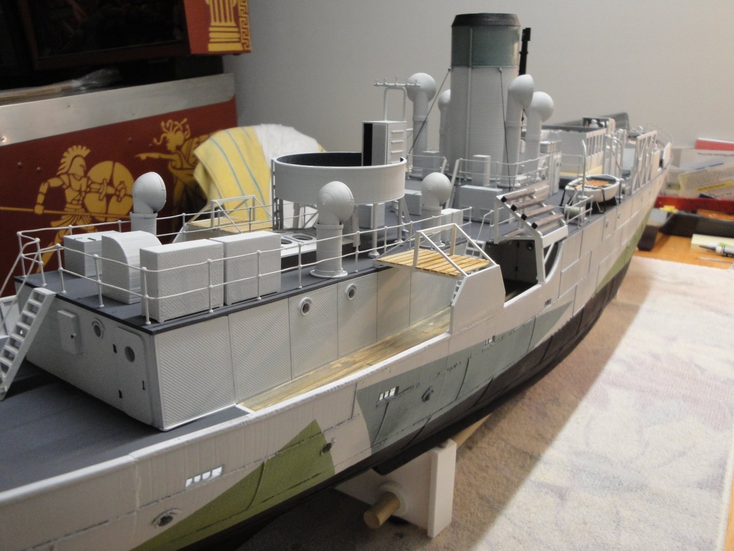
After the supports for the rafts, we need to install the cabinets and lockers for the ammunition. Again, this is done from historical pictures and the readers should keep in mind that this arrangement has evolved multiple times throughout the life of the ship. We also add the rear gun turret, after improving it a little bit. The anti-flak cabin is just a big block of PLA, in the kit. It would take way too much work to hollow it (the material is so hard) and I wish the designer would have done it in parts to assemble. So, in order to give it more dimension, I added a front wall and frame around the opening. The "stuff" above the cabin is made of brass wires, welded together and provide 5 hooks for the lines between the main mast and the rear gun tub. One painted and installed, it looks pretty decent and gives the illusion that it is indeed hollow: That pretty much concludes the Module #5. The machine gun is being 3D printed in resin and I do not have it yet. A few overall pictures to satiate your impatience and curiosity: Next will be Module #6, the rear deck. Yves


- 321 replies
-
- 19
-
-
-
- Finished
- Flower-class
- (and 1 more)
-
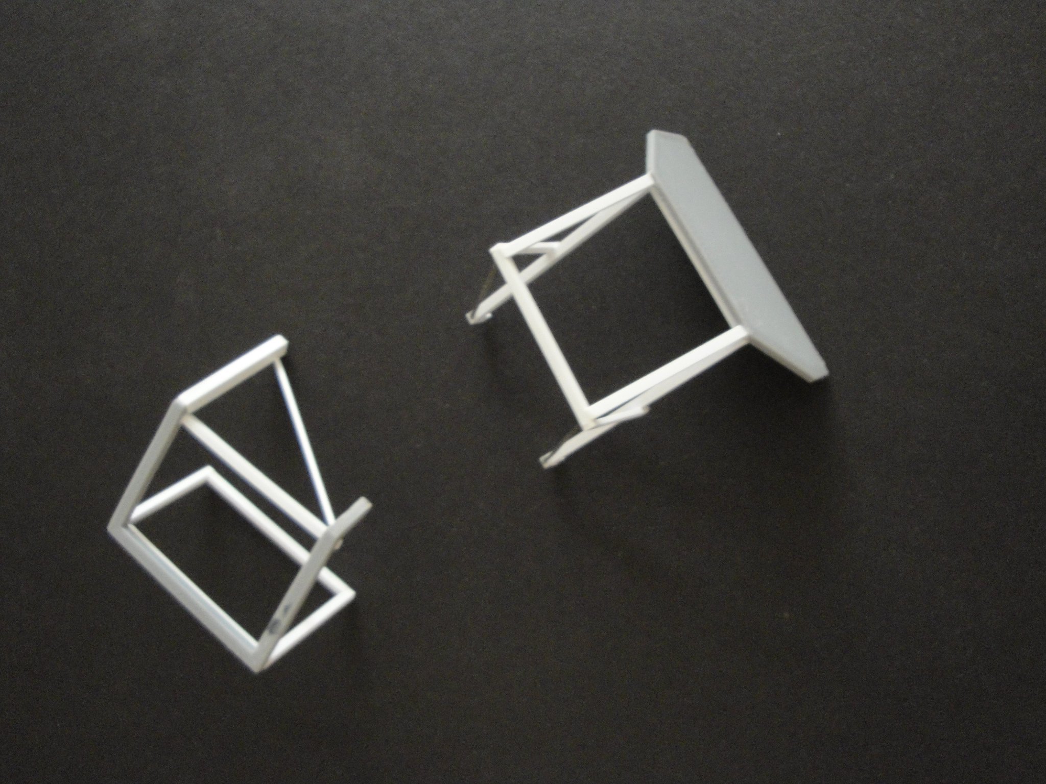
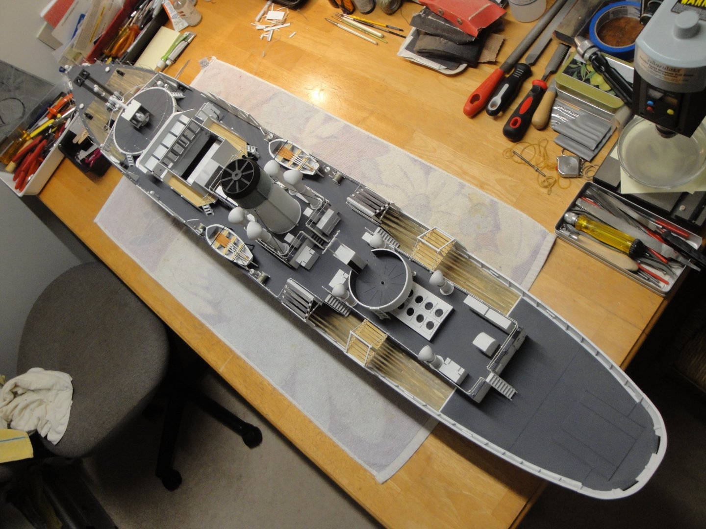
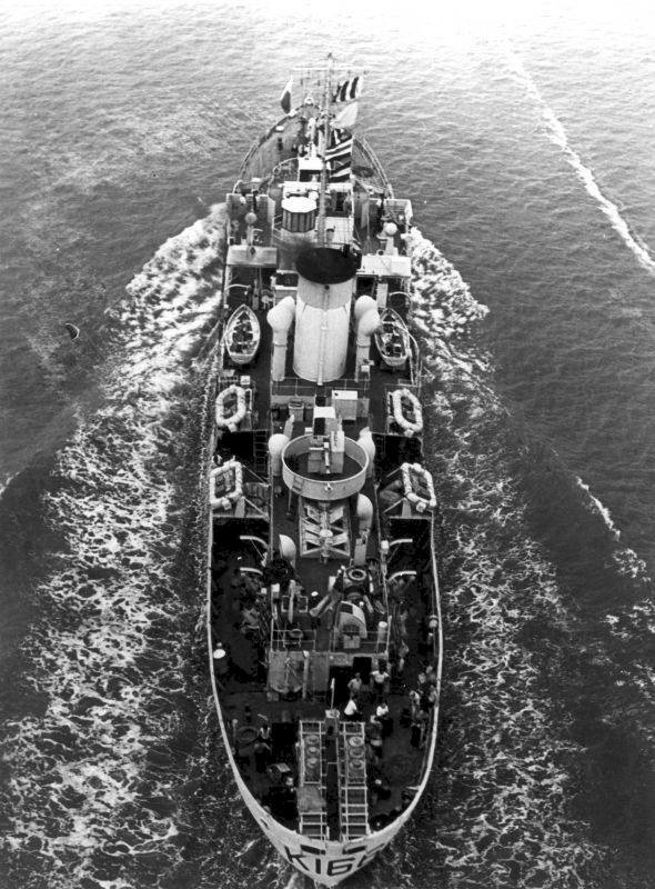
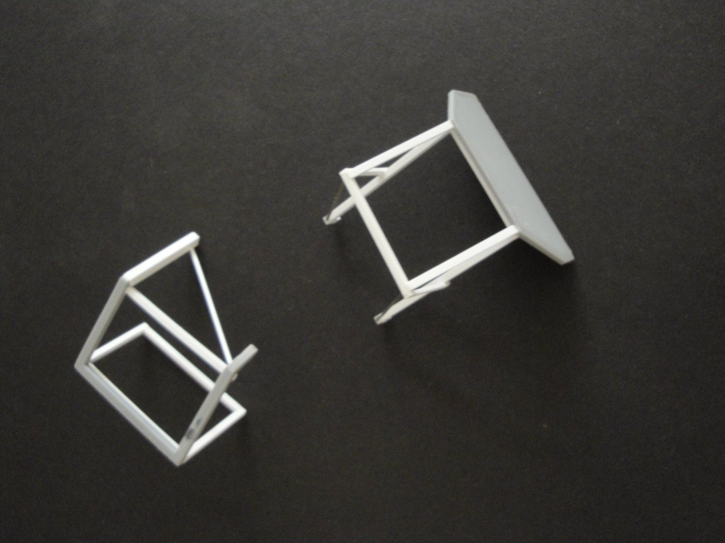
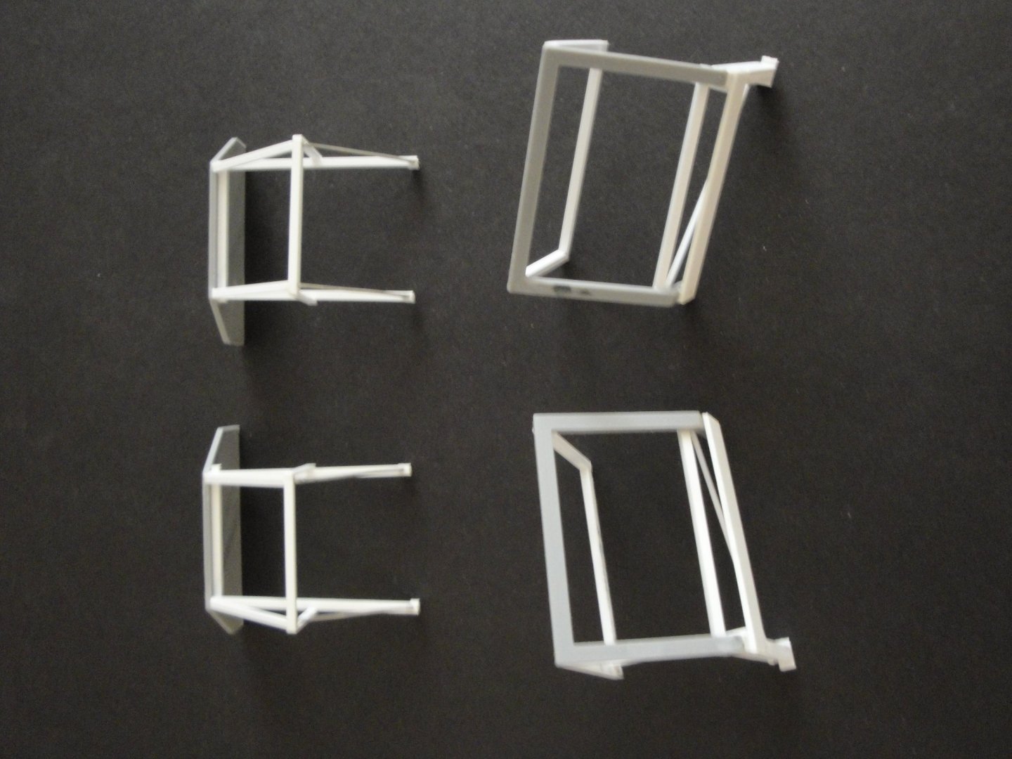
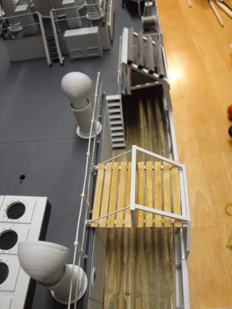
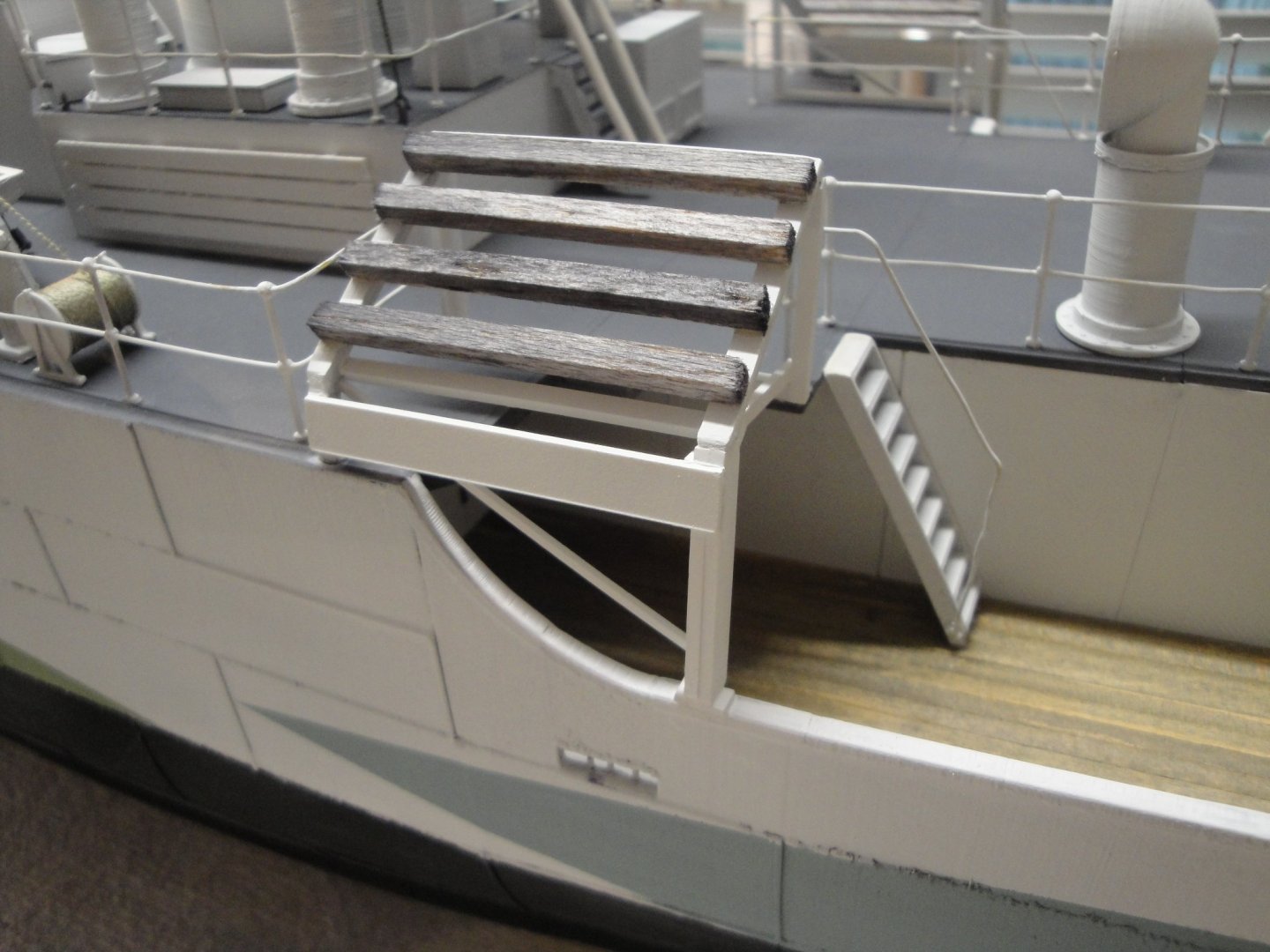
The plain vanilla kit does not present two of the main features of HMCS Snowberry: the raft supports. The kit offers "Raft support" but they do not match the way Snowberry was rigged. I have had to "hand made" these, which comes as a welcome contrast after printing pretty much all the parts needed. In the picture below, you can see the first Raft support located right behind the end of the forecastle and the support protected by some shielding: The shield is the part from the kit (protecting the front gun), reduced in length, with 40% reduction. Everything else is built with styrene strips and a lot of adjustments: Once in place, it provides the ship with a nice look: The rafts are not yet ready and will be added later. Below is where we stand at that moment: Yves


- 321 replies
-
- 17
-
-
-
- Finished
- Flower-class
- (and 1 more)
-
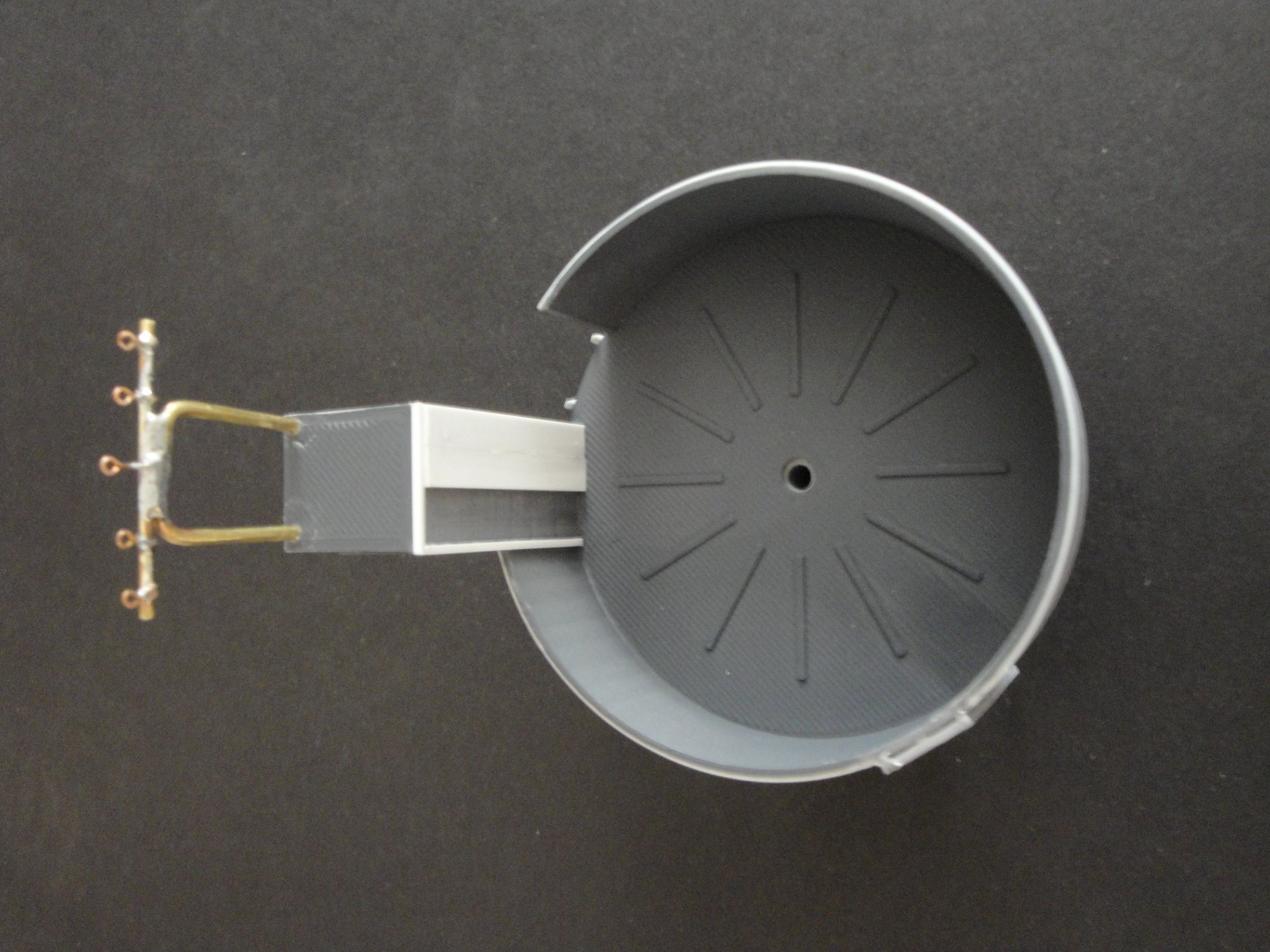
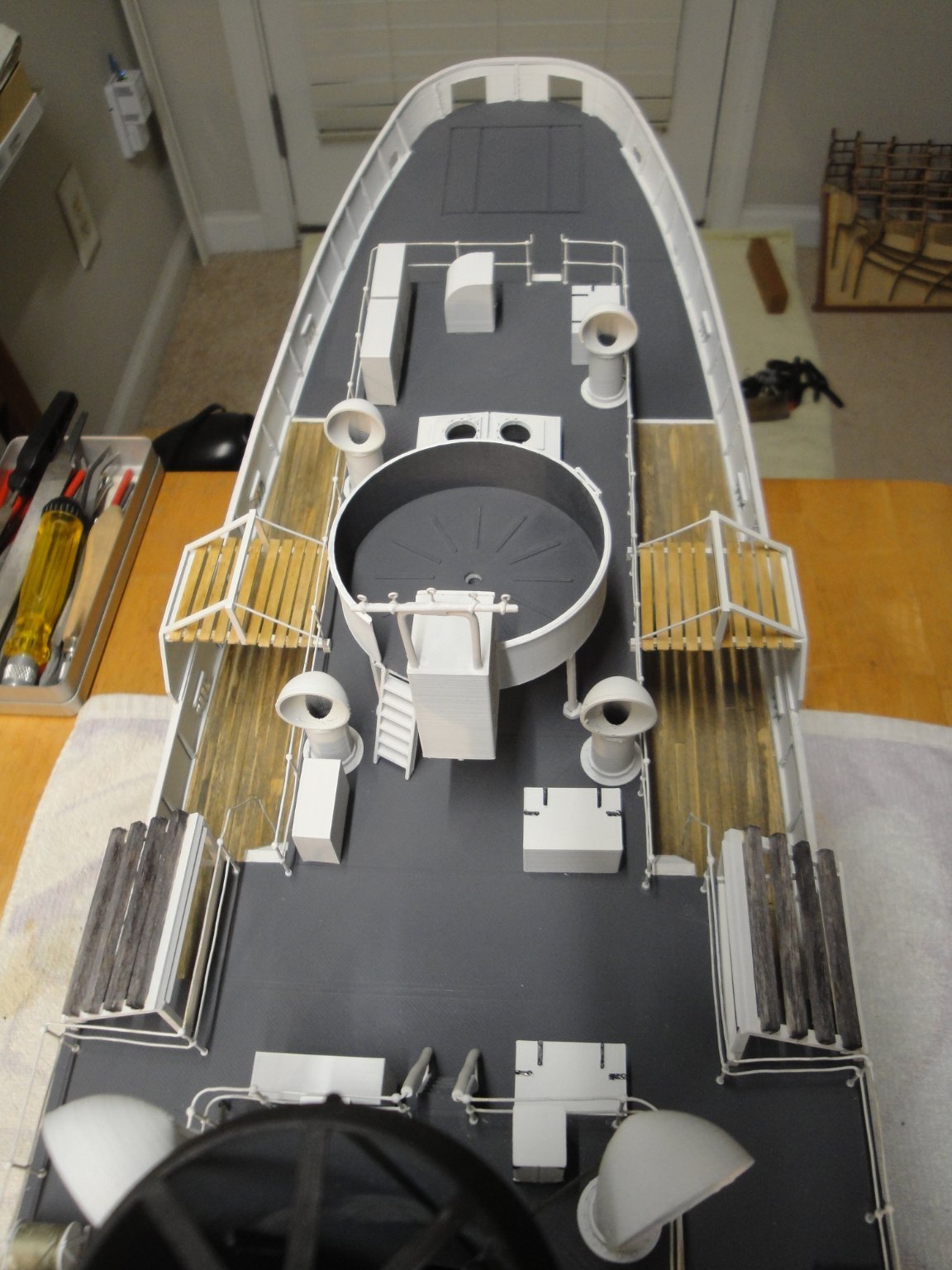
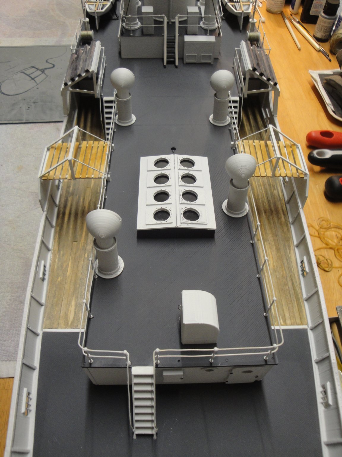
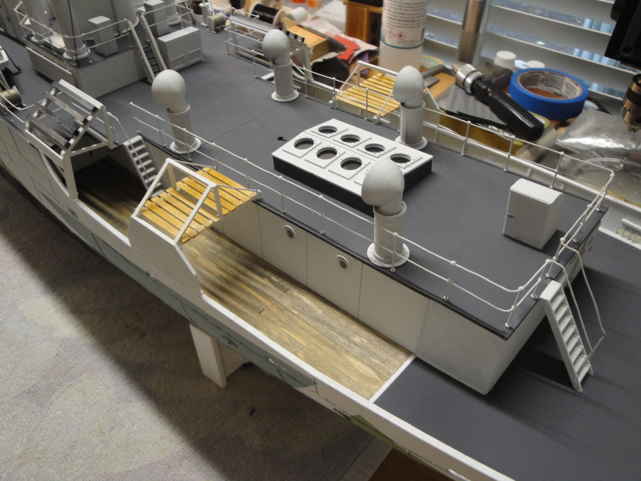
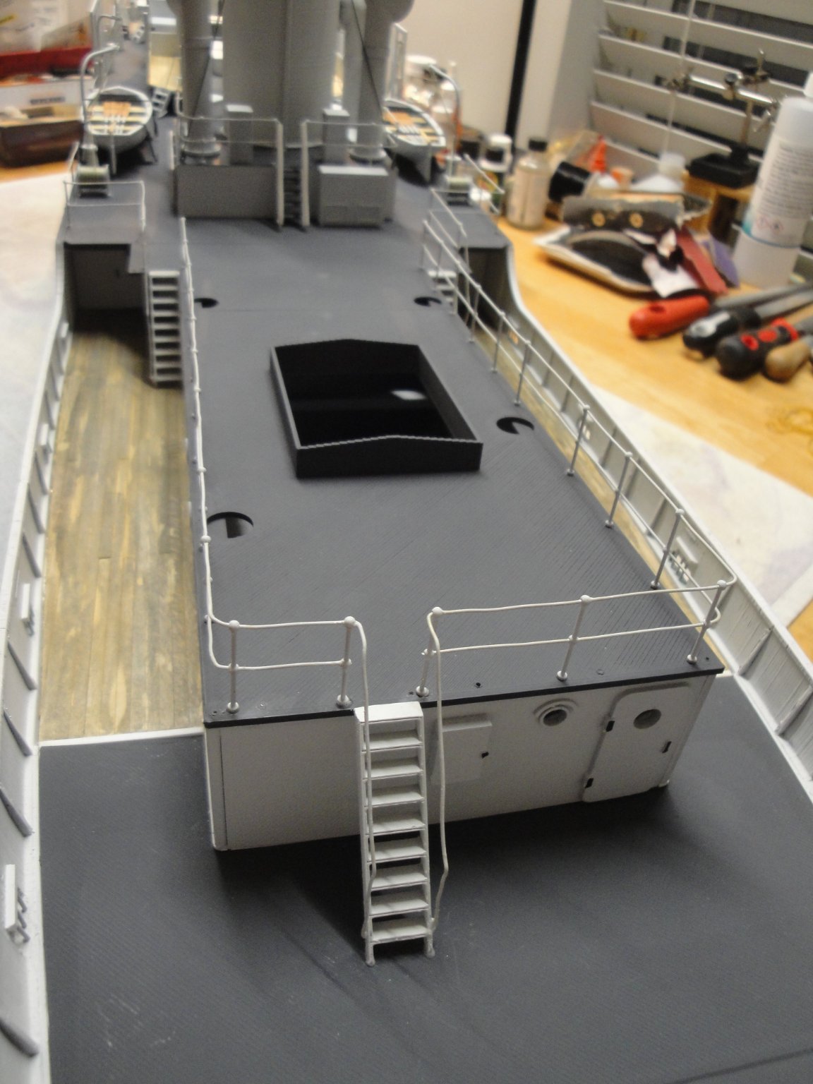
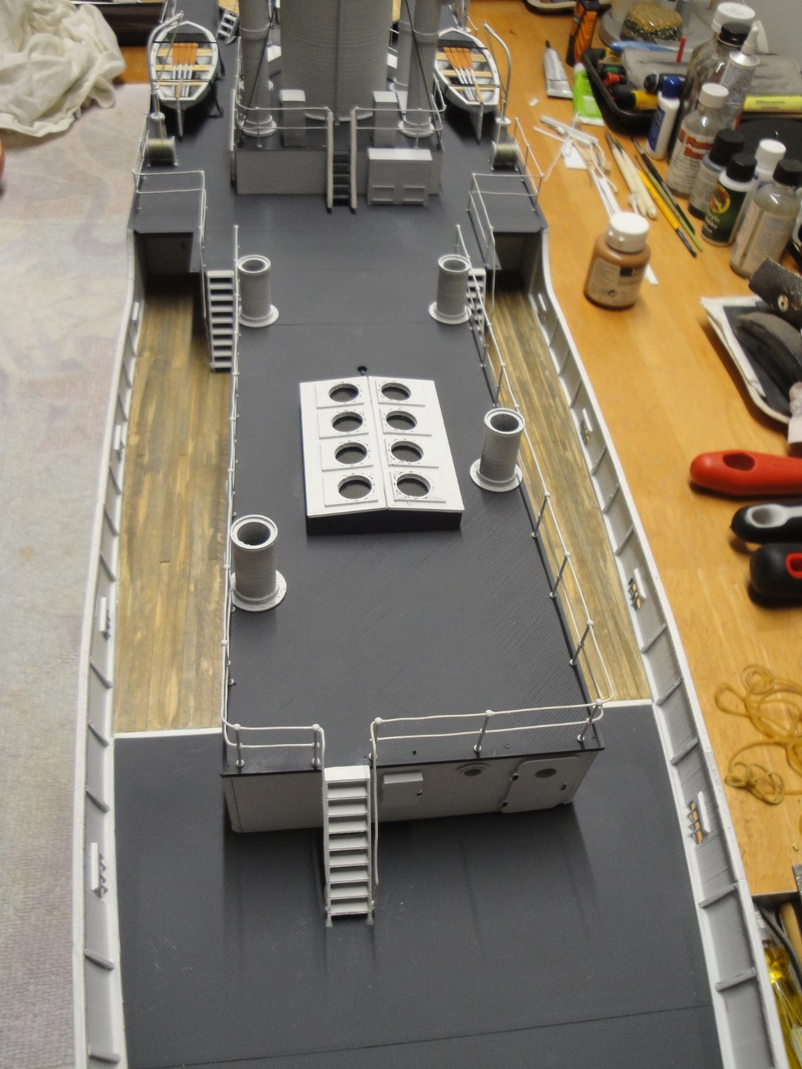
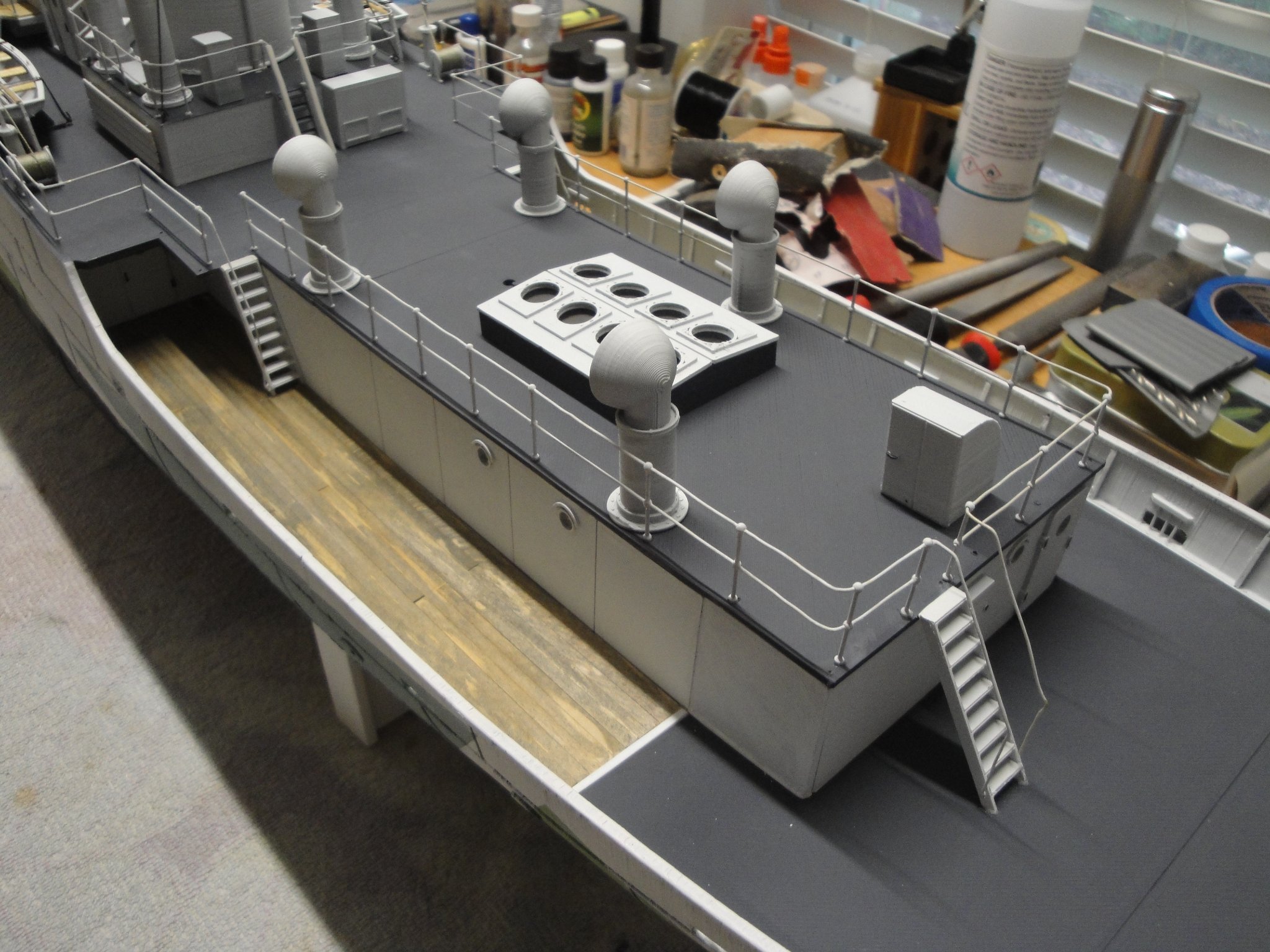
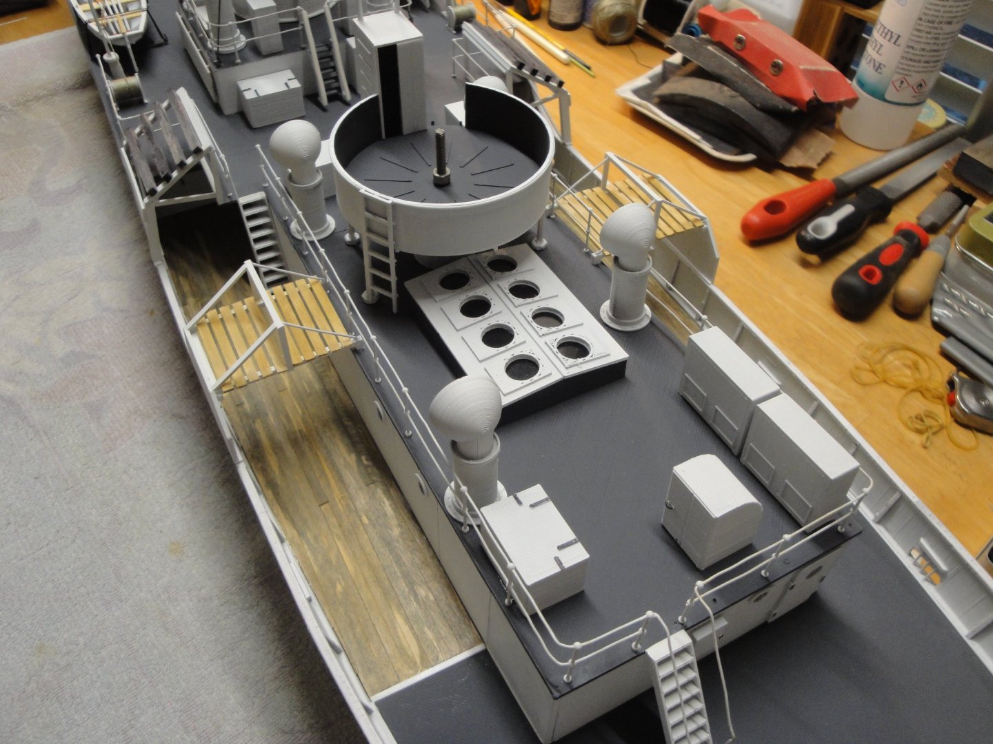
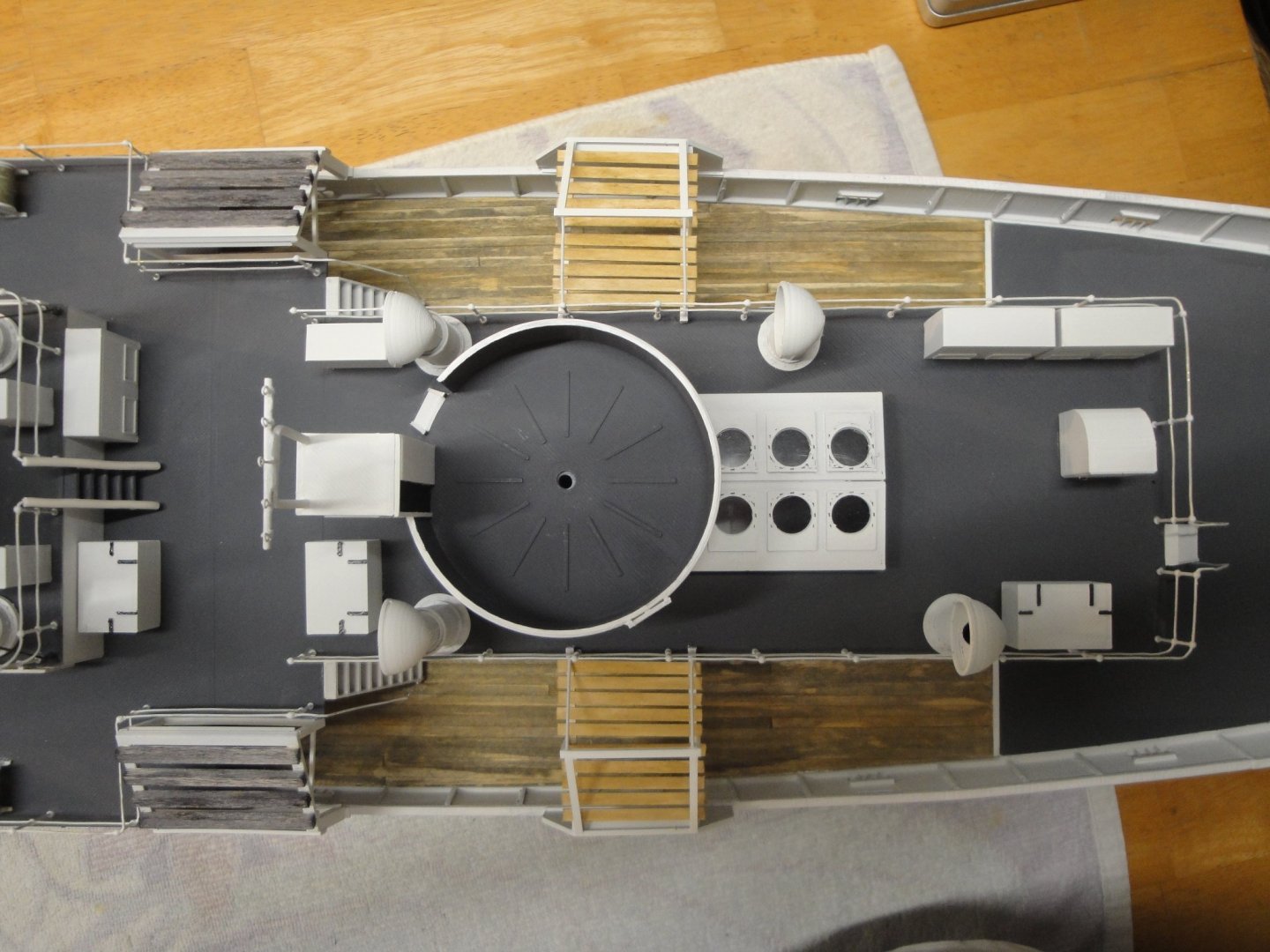
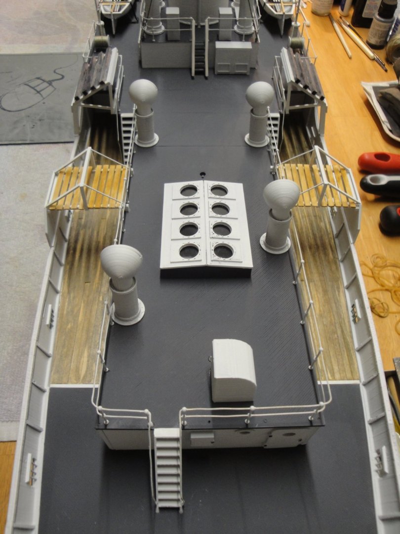
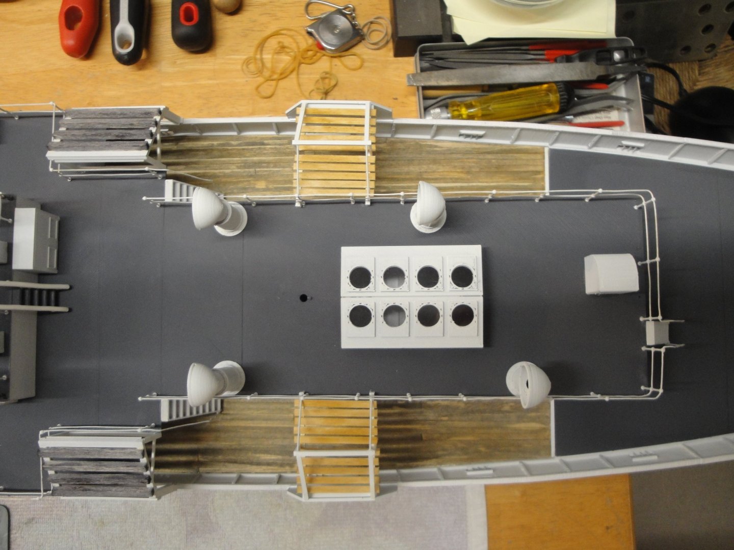
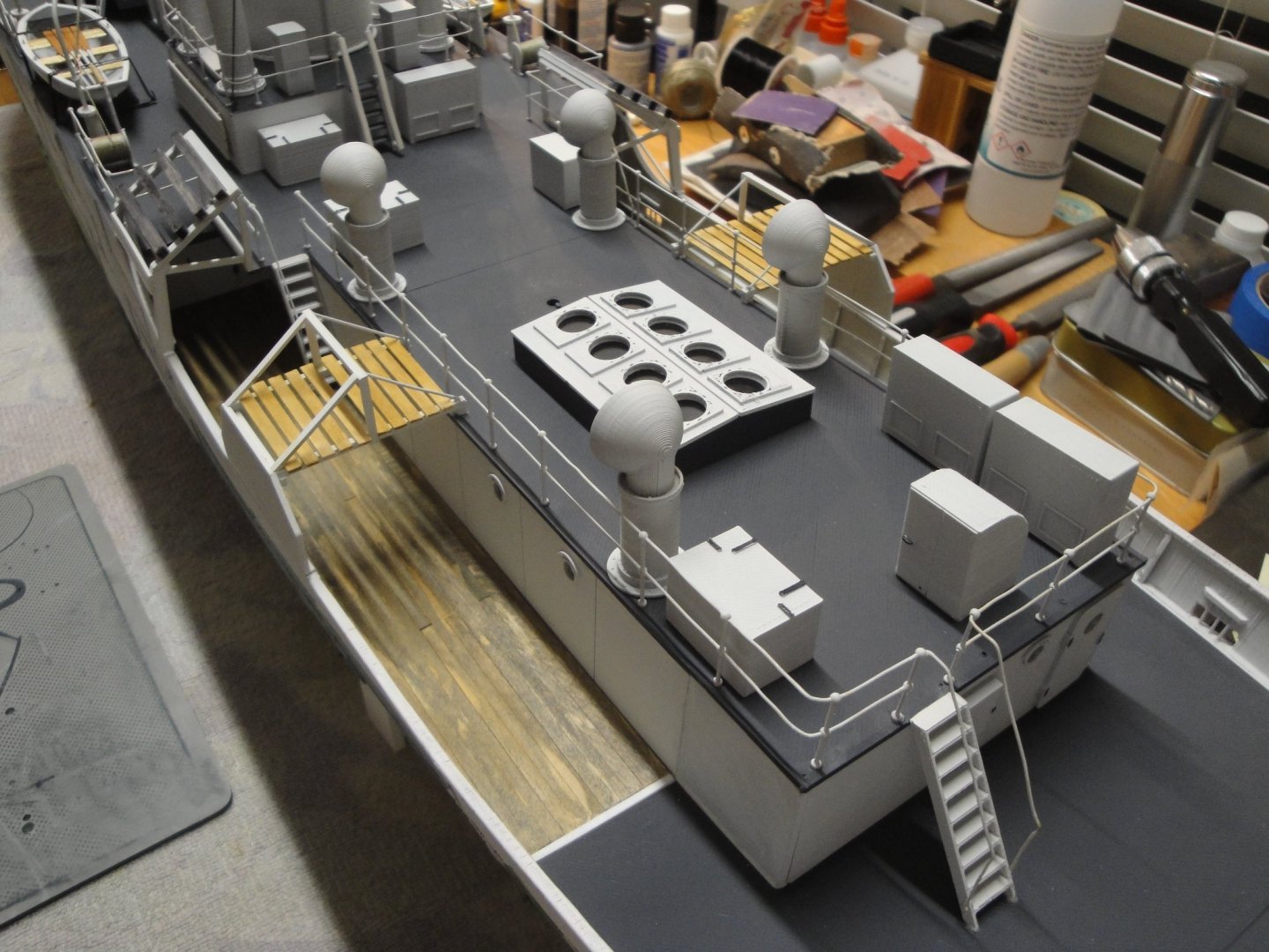
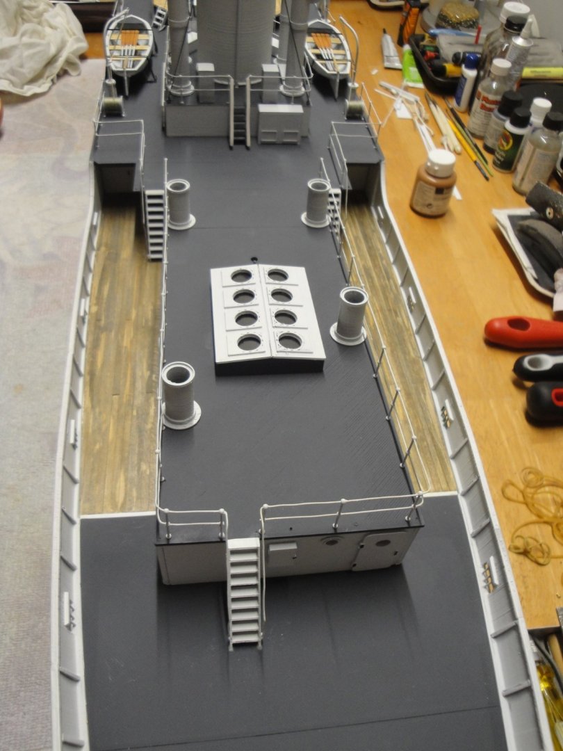
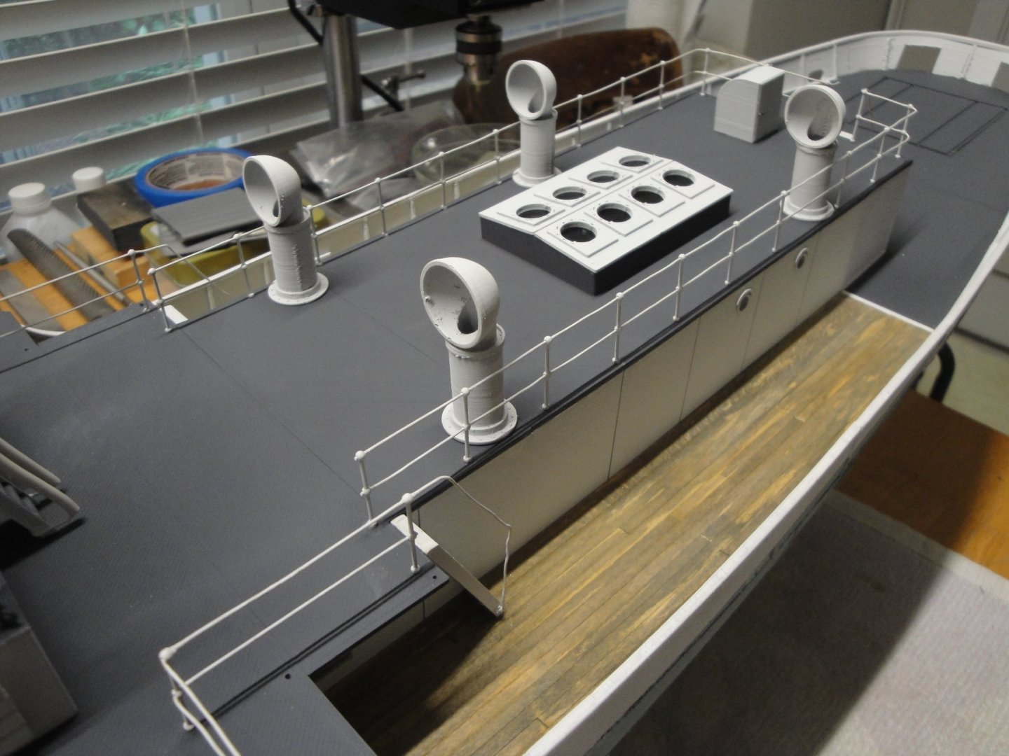
MODULE #5 - THE ENGINE ROOM This is a complex module, not so much as it is described in the kit, but because of all the necessary work to make it look like the HMCS Snowberry. We start with a bare roof and its extension, which has been described in a previous post: The railing is added. I like to do the railing first, as it is delicate and as the stanchions need to be inserted in a particular order. All the straight lines are glued first, the rails are then inserted, bent and the remaining stanchions are added. It is not perfect but looks quite convincing from a couple of feet away. Next, we add the skylights after gluing a piece of clear plastic underneath: The cowl pipes are added as well as cowls and access way: So far, it is all 3D printed and straight from the kit, with the exception of the cowl supports, reduced in height by 10%. Yves


- 321 replies
-
- 10
-
-
- Finished
- Flower-class
- (and 1 more)
-
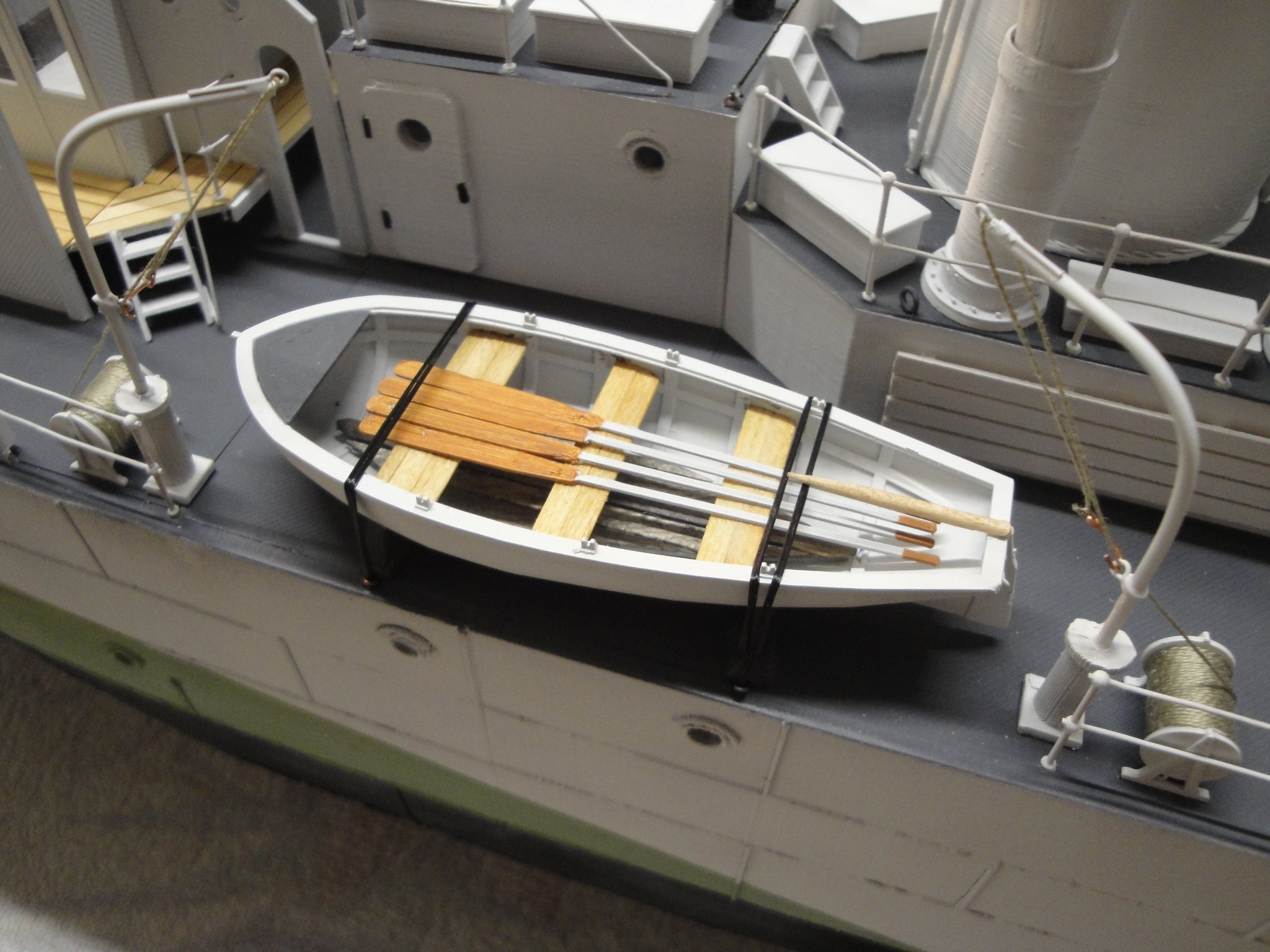
To conclude on Module #4, I owed you a picture of the finished dinghies, with their set of oars. Again, these are 3D printed, painted white and dry brushed with some acrylic raw Sienna paint. Next is Module #5, the top of the engine room. Yves

- 321 replies
-
- 10
-
-
- Finished
- Flower-class
- (and 1 more)