


Bob Cleek
-
Posts
3,374 -
Joined
-
Last visited
Content Type
Profiles
Forums
Gallery
Events
Posts posted by Bob Cleek
-
-
A spritz of the original WD-40 ought to do it. The extension nozzle on the spray can makes a neat job of it. Do not, however, use any sort of silicone lubricant on your tools or anywhere in your modelling shop.
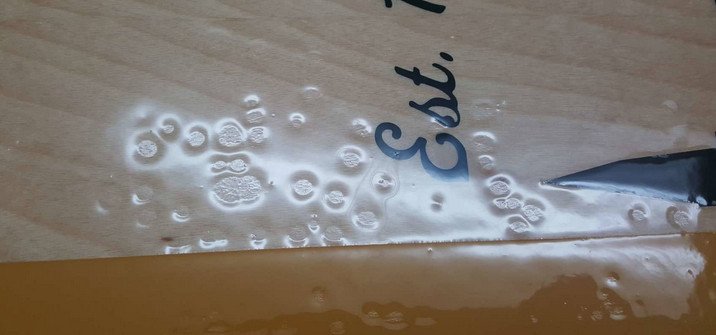
WD-40 now makes a silicone lubricant called WD-40 Specialist Silicone Lubricant. I'm sure it's good stuff, for what it is, but the professional rule of thumb is that silicone of any kind is verboten in any environment where it can contaminate items which are to be painted. Surfaces contaminated with silicone are impossible to paint. Any bit of silicone, even microscopic silicone dust particles, will cause "fisheyes" in fine paint finishes. ("Fisheyes" are small dimples in an otherwise smooth coating surface.)
The use of silicone spray lubricants on things like saw blades discharge microscopic bits of silicone onto the saw surfaces, and everything else in your shop. Every single speck of silicone will produce one of the "craters" or "fisheyes" show in the below photo. The only silicone you'll ever find inside an automobile body and paint shop will be the endowments on the ladies in the parts companies' calendars! I don't allow it in my home shop, either.
-
-
-
2 hours ago, mtaylor said:
I suspect that the term "tall ships" comes from a marketing department somewhere to advertise for one the "tall ship" gatherings that happen. It separates them from the regular steel navy/cargo ships.
Yes, indeed!
30 minutes ago, Jim Lad said:I believe the term 'Tall Ships' was thought up some years ago by the European sail training mob in a advertising campaign.
John
Absolutely correct.
The term "tall ship" was popularized by a poem by John Masefield called Sea Fever:
I must down to the seas again, to the lonely sea and the sky,
And all I ask is a tall ship and a star to steer her by,
And the wheel's kick and the wind's song and the white sail's shaking,
And a grey mist on the sea's face, and a grey dawn breaking.The first line is often misquoted as "I must go down to the seas again." The original version of 1902 reads 'I must down to the seas again'. In later versions, the author inserted the word 'go'. Source: https://poemanalysis.com/sea-fever-john-masefield-poem-analysis
Author Joseph Conrad who spent 1874 to 1894 at sea and was quite particular about naval terminology used the term "tall ship" in his works; for example, in The Mirror of the Sea in 1903.
Henry David Thoreau also references the term "tall ship" in his first work, A Week on the Concord and Merrimack Rivers, quoting "Down out at its mouth, the dark inky main blending with the blue above. Plum Island, its sand ridges scolloping along the horizon like the sea-serpent, and the distant outline broken by many a tall ship, leaning, still, against the sky." He does not cite this quotation, but the work was written in 1849.
These early usages appear to be simply poetic descriptions as would be "a big car" or "a long train." It had no other specific nautical meaning.
Modernly, "tall ship" is often used generically in reference to large, classic, sailing vessels, but is also a technically defined term invented by Sail Training International for its purposes and of course, Sail Training International helped popularize the term. The exact definitions have changed somewhat over time, and are subject to various technicalities, but by 2011 there were 4 classes (A, B, C, and D). Basically there are only two size classes, A is over 40 m LOA, and B/C/D are 9.14 m to under 40 m LOA. The definitions have to do with rigging: class A is for square sail rigged ships, class B is for "traditionally rigged" ships, class C is for "modern rigged" vessels with no "spinnaker-like sails", and class D is the same as class C but carrying a spinnaker-like sail. Sail Training International has extended the definition of tall ship for the purpose of its races to embrace any sailing vessel of more than 30 feet (9.14 m) waterline length and on which at least half the people on board are aged 15 to 25. This definition can include many modern sailing yachts that few who use the term to describe large sailing vessels would recognize as "tall ships."
Outside of Sail Training International's unique commercial parameters, the term "tall ship" is meaningless as nautical nomenclature and people who use it to describe any particular sort of vessel, such as a large square-rigged one, are only proclaiming their status as landsmen.
- BETAQDAVE, Keith Black and mtaylor
-
 3
3
-
3 hours ago, Gregory said:
I apologize if i missed it in all of this, but what is a good generic overall length for a belaying pin?
( I'm not particularly concerned about the rivet counters surveying one of my models and proclaiming that my belaying pins are 2 scale inches too long..
 )
)
One might as well ask the same question about a gentleman's privates. If it looks right, it is right. It takes looking at a lot of them in real life to instinctively judge whether one is too short or too long. It depends on the use intended and is relative to the size of the line that going to be tied to it.
-
18 hours ago, JerseyCity Frankie said:
The other reason for multiple figure eight turns on the pin, as opposed to just a single knot on the pin, is so the crew can “ease under strain”. By taking off just one of the three turns 1/3 of the friction is removed, right? Two turns removed remove 2/3 of the friction, When the time comes to ease a load back onto the deck-for instance when lowering a Mainsail on a schooner- you can’t just cast the line off the pin and let the line run. This would likely break the gear. The load has to be controlled, not allowed to run away. To do this the single crewperson removes turns on the pin until the line begins to render by itself due to the load-the weight- on the line. In this way a single person can control the line as it is eased, and can control the speed too. The friction is still doing the work and the crewperson isn’t holding the weight, they’re allowing friction on the pin to control the speed at which the line pays out.
Another place the single knot on a pin idea can’t work is on sheets. Sheets have to be constantly adjusted and if it’s windy the sheets are under a great deal of strain. But a single crewperson can ease a sheet by easing turns on a pin. Easing a sheet tied to a pin with only a knot is possible but would be dicy and require the attention of a team of crewpeople. And a sheet with a knot attaching it to a pin is constantly tightening that knot as the wind tugs on the sail and I’m afraid after a short while that sheet would need a knife to get it off.
I hear what you're saying, Frankie, but it doesn't comport with my own experience. Myself, I've never had any problem easing off a length of line from a pin, or horsing up from one, either. If you can hold the line before you even throw it around the bottom of the pin, you ought to be able to hold it just as well when casting it off. If for some reason, you want more friction, it's easy enough to take a quick turn around the top of the pin.
Contrary to your assertion, the coefficient of friction in line under load is not a "linear equation." Each of the turns does not carry an equal portion of the friction or of the load. The first turn carries most all of it. Additional turns are just "window dressing." Ever notice how nothing comes free until you get down to the last turn or so? And, obviously, nobody ever "casts the line off the pin and lets the line run" more than once.
Belaying pins are designed to take vertical strains more or less parallel to the direction of the pin and never horizontal (shear) strains at right angles to the pin, which can snap a wooden pin. The pin itself isn't meant to take the majority of the strain from the line, but rather it's the pin rail itself where the greater part of the strength, as well as friction, comes from. Sheets, which generally carry horizontal strains, should never be belayed directly to a pin rail. Sheets should be carried through a block or around a winch to provide a fair lead to a cavel or deck cleat. Pin rails are for halyards and other lines from aloft.
I've belayed lots of lines to pins and hitched lots of sheets to cleats in my 70 years and I've never, ever, "needed a knife to get it off," nor even a fid. That's the advantage of a half-hitch.
This thread got me curious and I did a bit of googling. It seems there are many sites purporting to show how to belay a line and hang a coil and almost as many ways the people posting those instructions say it should be done as there are people posting. Welcome to the internet, the world's largest collection of self-appointed experts!
As the saying goes, "Different ships, different long splices." I suppose. Being "of a certain age," when I was growing up and infatuated with all things maritime, having a father in the shipping industry in San Francisco when it was the busiest working seaport on the West Coast, there were still a fair number of old timers around "on the beach" who'd served their apprenticeships "before the mast" sailing around the Horn in the big four-masted barks and all sorts of smaller sailing craft. Some were kind enough to share what they knew (and probably nobody else cared to hear them talk about) with kids like us. That's how we learned our basic seamanship. Somewhere along the way, we lost the continuity of that maritime culture. Today, it's become quaint and of interest to many, but it seems much of it has had to be recreated, rather than handed down in a direct line. A lot of the detail got lost along the way. There was a lot more to it than those "playing pirates" and singing "sea chanteys" today will ever know.
- Keith Black, el cid and BETAQDAVE
-
3
-
4 hours ago, JerseyCity Frankie said:
There’s tremendous confusion in ship modeling circles about how to belay on a pin but there is zero debate on the topic in the tall ship community. On a tall ship it is always THREE figure eight turns around both parts of the pin never two or less, never four or more. The turns are ALWAYS clockwise around the top of the pin, they NEVER go in the other direction. Debate creeps in on the subject of using a locking hitch on the third turn, some ships do, some ships don’t. Note that the decision to use a locking hitch is never at the discretion of the sailor, each ship will have a stated shipwide policy on locking hitches. Believe it or not.
The use of the three turns has everything to do with FRICTION for it is the friction that holds the line to the pin, not the binding force of a hitch. Three turns is all it takes to create enough friction to prevent any line in any load on any ship from “rendering” around the pin by itself. A line that would have sufficient force to render on three turns would break the pin or part the line itself and loads that are too strong for that wil go on bits or the like, not pins.
Well, what do you expect from anybody who calls them "tall ships?" Rubes for sure!
There wasn't any such thing as a "tall ship community" in the age of sail. Neither did real seamen spend half their time singing "sea chanteys" to the music of insufferable amateur concertina players.
Three turns will hold without a locking hitch, but that takes more work than a single turn and a half hitch twist. The three (or more) turns build an unnecessary wad of line on the pin and take that much longer to cast off. Consider doing it that way with soaking wet inch and a half diameter line and I think you'll agree. Some say multiple turns are required with modern synthetic cordage which is more slippery than natural cordage, and there may be some truth to this, although I've never experienced it in practice. Others say they do it that way on the "dude schooners" because they can't be sure the "guests" really know what they are doing.
It is not uncommon to take two opposing half-hitches on a mooring cleat, however, when the intermittent strains imposed by the vessel's surge alongside a pier or dock may cause a single half-hitch to work loose.
- el cid, Keith Black and mtaylor
-
3
-
7 hours ago, shipman said:
Ah, the photo's depict something I haven't noticed before.
The line is first looped in a figure of eight over and under the pin, maybe four or five times.
Then the crewman 'hand coils' the line. The coil is NOT passed over the top of the pin (as seen in so many models), but instead a 'loose' loop from the last winding over the top of the pin is past through the coil from behind, then over the top of the coil and then past back and over the top of the pin, securing the coil.
The coil is hung from that loop, which can quickly be lifted off again. The crew member must put his arm through the coil again to support it from falling untidily to the deck. May-be THAT'Swhy so many sailors only had one arm!
That's how I read the picture anyway; my main point being that the bulk of the coil doesn't actually go over the pin!
Not exactly. The fall is brought down to the pin and around (outboard) the bottom of the pin, then, with the fall held taut around the bottom of the pin, the loose line is grabbed in the free hand and given a half-turn twist and the resulting loop is cast over the top of the pin, forming a half hitch. That's it. No "figure eight over and under the pin, maybe four or five times." (All but the coil on the right of the four in the picture above look like some donkey has been wrapping the line around the pin over and over again.) That's lubberly and you'd get a start from the bosun's quirt if you tried that back in the day. All that is needed is the single half hitch around the top of the pin. the tension on the line and friction in the half hitch will keep it completely secure. Additional turns and hitches only make it more difficult to cast off the line when that time comes, and it sometimes comes in an emergency when seconds count.
Unfortunately, today it seems belaying a line to a pin is almost never seen done correctly. They always seem to over-do it with multiple turns. Seamanship is another of the dying arts.
The remaining line laying on deck is then coiled up in one hand (and not around your elbow, either!) Each loop of the coil must be given a half turn with the fingers as it's coiled to keep the line laying fair and not kinking. When the coil is made up in one hand (or sometimes on deck it it's too large to hold, which can frequently be the case in large ships), it is picked up and the free hand is reached through the middle of the coil and a bight is pulled between the line tied off at the pin and the coil and pulled through the center of the coil and over the top of the coil, taking a twist as it does, and the loop resulting from that twist is hung over the top of the pin, thereby hanging the entire coil on the pin. To cast off, the loop is simply pulled off the pin and the line freed from the pin, with the standing part then coming off the coil without fouling.
I can do it a heck of a lot faster than I can tell you how to do it. It's one of those details on a model, particularly when restoring an older model, that tends to indicate that the model was "sailor built" by somebody who actually had some blue water under their butt and knew what they were doing, instead of just building a model from a kit.
- Keith Black, mtaylor, stuglo and 1 other
-
4
-
26 minutes ago, JerseyCity Frankie said:

Good points. Another error frequently seen on model pinrails is that the coils hanging from the pins fail to correspond to the length of the particular falls depicted. A three=part purchase is going to take a third more line than a two-part purchase to two-block it, i.e. a third more the working length. The length of the falls will also vary depending upon the distance from the uppermost block to the pinrail. Neat coils, all of the same length don't exist in real life. Falls should be the correct length to properly portray the coil in minature.
-
1 hour ago, gsgreene said:
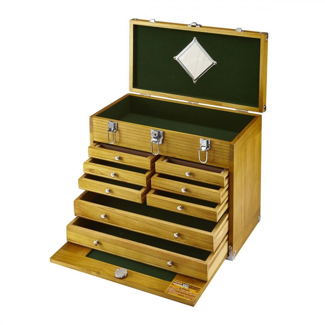
I'm trying to clean up my workbench before Christmas and I'm struggling with the numerous X-acto handles, blades parts etc. in various locations. I would like some way of easily organizing all of these but haven't got any really good ideas. I have some of the wooden box sets that hodl some items but the plastic inserts aren't very secure and fall out, plus I'd like to have everything in the same place. I'm sure many others have dealt with this so does anyone have any good ideas or pictures of how to store these?
The old wooden box sets (which always had a lot of tools in them for which one had no use whatsoever!) had wooden separators instead of the cheesy plastic ones we see now. You might build some wooden dividers into your wooden boxes and consider throwing the plastic ones out. Good storage keeps everything in its place and makes for much more efficient working. Without it, I spend way too much time looking for a tool "I know I laid down here somewhere." I find machinists' tool chests perfect for storing categories of small tools, which makes sense because that's what they are designed for!
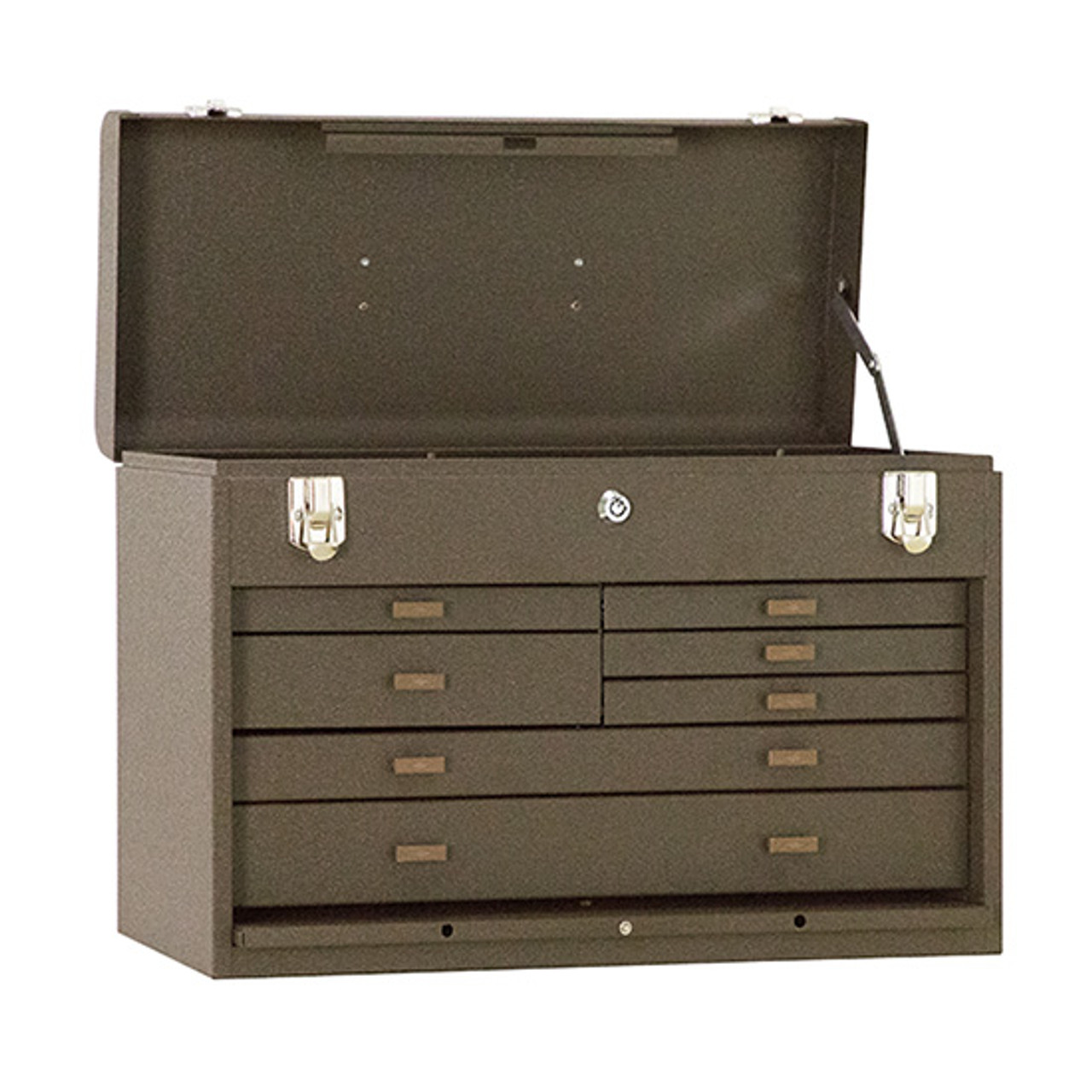
 Kennedy professional grade chest at about $300, but much better, with ball bearing drawer slides: https://allindustrial.com/99-010-520-7-drawer-machinists-chest/?device=c&keyword=&campaign=296456090&adgroup=pla-4582558307670047&msclkid=ce02091052cb141766b454e17e367e67&utm_source=bing&utm_medium=cpc&utm_campaign=**LP Shop - Catch All&utm_term=4582558307670047&utm_content=Shopping Catch All
 Tool chests come in a myriad of configurations, many "stackable" on rolling cart bases and at many price points. The good ones aren't cheap, but nothing good ever is. For modeling purposes where we aren't going to be loading them up with hundreds of pounds of steel machine tooling and the like, for which the good ones are designed, the lighter and less expensive models will serve without requiring taking out a second mortgage. (Costco sometimes has quite good stainless steel "house brand" models at excellent prices. Harbor Freight has lots of options at, well..., Harbor Freight quality, but a decent enough value at their low prices and suitable for modeling purposes.) Proper tool storage is essential to good craftsmanship and a good tool box is as important a "tool" as any. The less time "looking" and "searching," the more time working. Spending the money on a good rolling tool cart may not be as exciting as spending it on a "sexy" tool, but your tool box is the one tool you will use every time you use any other tool you store in it. And if you live with other people in your household, the locks on most tool chests come in very handy.

-
4 hours ago, druxey said:
I'm sure that there were local variations, but they were generally longer and much thinner than seen on most models. The handles would be less than 2" in diameter (try grabbing a chunky one in your hand!) and the overall length about 18" long. See:
It's sort of surprising that the NMM would collect, inventory, and store such a common artifact made as recently as 1925. I suppose it's almost 95 years old now, though. It makes me feel old! Another item for my "Kids today" file, as in: "Don't know what a belaying pin looks like!"
- Keith Black, mtaylor and druxey
-
3
-
1 hour ago, KeithAug said:
Yes that's how I did it until I got frustrated with having to use 2 hands. Now it is easier and quicker which is important when you change blades frequently as I do.
I do a lot of my work with fine toothed slitting saws and thy are much more difficult to jamb than a TCT saw.
Quite true.
-
-
2 hours ago, BETAQDAVE said:
Bad news guys, I am afraid that Doris will no longer continue with her presentation of her modeling on our site. I went to the modelforum.cz to view her Royal Katherine build log and found a quote (July 14, 2019) where she has said as much.
 Apparently she was expressing her frustration there at having to repeatedly respond to the same questions over and over even though she had provided many detailed photo tutorials previously.
She is apparently on several different modeling forum sites at this time and wanted to cut down on the time spent on them to devote more of her time to actually working on her modeling projects. Personally, I think that she is looking for more guidance for her from the sites. Unfortunately for her, she herself seems to be the authority on the subject and there are few out there that know more about the subject than her.

However if you want to continue following her work, (with the availability of the translation programs) just go to the modelform.cz website and you can follow her there. I am saddened by this news as my wife and I can't help but appreciate her artistry and find that I continue using some of her techniques. Still, I wish her continued success on her modeling.
I guess this makes Doris a "canceled Czech."
Seriously, though, I stopped following her logs on a regular basis for much the same reasons given for her abandoning posting on this forum. When I follow a log, I read every post by the builder and I learn a lot. Her work is truly exceptional and she is a highly skilled modeler. That said, her log became, to my mind, "cluttered" and overwhelmed by gushy compliments and "fan mail" which made reading her log tedious. I'm sure every build logger appreciates the compliments and positive encouragement. Ours is a lonely hobby under the best of circumstances and a compliment from anyone who knows what they are looking at is always treasured. Doris always made sure she acknowledged every comment and "like." That must have ultimately made tremendous demands on her time and caused her to "burn out" on MSW. I, also, was annoyed by the many times she was asked what materials she used or how she achieved a particular effect when those questions had been asked more than once before and answered in depth previously. Such questions impose upon everyone reading the log. I submit that it's enough to occasionally express appreciation for such masters' sharing their work and leaving it at that.
-
Or lay a piece of softwood on the table, raise the blade, and jamb the face of the block of wood up against the saw teeth and hold it fast there, then turn the arbor nut. The teeth bite into the wood when the arbor is turned by the wrench. I've never changed a table saw blade any other way.
-
6 hours ago, bruce d said:
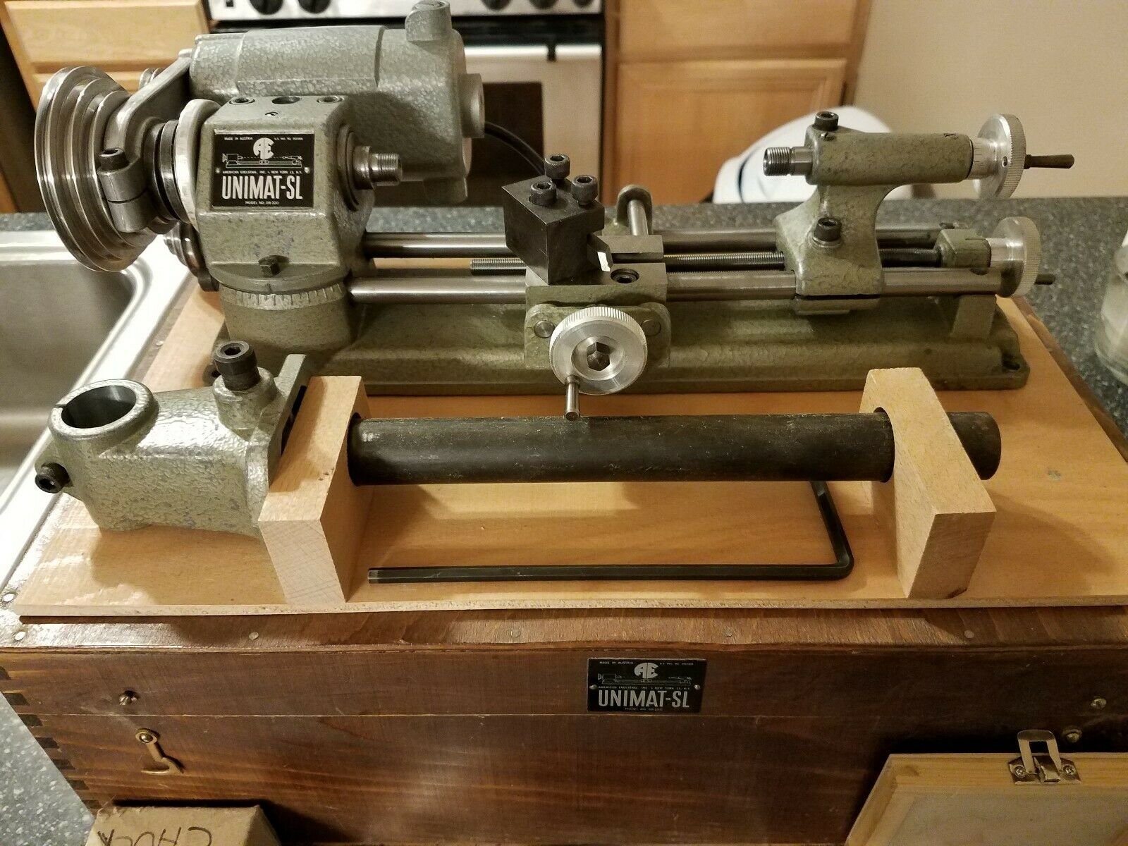
Unlike the UNIMAT 3 it has a built-in taper turning facility by adjusting the angle of the headstock. I assume you have a three jaw chuck.
"In the spirit of full disclosure," the above isn't' exactly accurate. It does have a swiveling headstock, but turning tapers on a piece of any length will require providing your own method of offsetting the tailstock center or providing some sort of traveling backrest to prevent deflection of the workpiece.
-
41 minutes ago, shipman said:
Hmpf! I've had two Unimat lathes for years, an SL and a later white enamel square shaped thing. I understand these are capable of tackling clock/watch work, so I would imagine 8mm brass belay pins would be possible. The trouble is, I've never used a lathe, so haven't a clue where to start. Speeds? Cutting tools? For such a 'simple' job I am in danger of over complicating what needs to be done. I've been toying with using an electric drill and files (which should be possible), then I remembered I have these lathes tucked away. Any advice please?
Yeah, you really don't need them. Just pack 'em up and ship them off to me. You can put the storage space to better use!
Just kidding. You've got a Unimat SL and what sounds like a Unimat 3, its successor model. Both are still in demand, although they haven't been in production for decades. Tooling is available on eBay... at a price. Until the Sherlines came along, they were state of the art for modeling. They aren't exactly "watchmakers'" lathes, but they will do that work if the watchmaking spindle is used. These are available second hand, but aren't cheap. As a general purpose mini-lathe and mill (they are combination machines that can be set up for milling and drilling as well as turning) they are great as long as you have the tooling for them and don't expect them to do very heavy work, which shouldn't be necessary for modeling. They also have table saw, jig saw, grinding, disk sanding, jointing and planing, and milling attachments, as well as a thread-cutting attachment. Modern quality scroll saws, and the Byrnes' table saw and disk sander are far better than the Unimat attachments, but in their day, they were the best there were for modeling. Brass belaying pins are a piece of cake on the Unimats. Grind out a tool bit to the belaying pin's profile and you can turn them out in a jiffy.
All of the instruction manuals and project books for the Unimats are online in PDF format. Google them up and print them out and put them in a binder. Follow those instructions and you'll be on your way. Don't worry so much about speeds and cutting tools. You won't be cutting exotic or super hard metals with it. All you need to know is in the manuals. Gerald Wingrove's The Techniques of Ship Modeling addresses the Unimat SL's capabilities extensively, including using them for turning out wood and metal belaying pins.
In good shape and with only basic tooling and no optional attachments, the Unimat SLs are bringing as much as $800US on eBay these days. Of course, you can then spend $1,000 or more on a collet holder and collet set if one is so inclined!

- Canute, paulsutcliffe, Jorge Diaz O and 2 others
-
5
-
-
2 hours ago, Jim Rogers said:
All clove hitches from beginning to end secured with diluted white glue (PVA).
Depending upon the scale, I suppose. In full-sized practice, a half-hitch is taken around each shroud, but the ratlines are secured to the outside shroud at either end of the length of the ratline by splicing a loop in the end of the ratline and then lashing that to the outermost shrouds. In practice, a clove hitch on the outside end would loosen and untie in short order. If you think tying scale half-hitches is tedious, just try splicing scale line!
-
I discovered In the Wake of the Bounty on Amazon Prime TV last night. It's a one-hour long combination documentary made in 1934 of a visit by a film crew to Pitcairn Island in 1930. The documentary of life on Pitcairn Island in 1930 is interspersed with a dramatic portrayal of the mutiny story. I expect it would be of interest to many, and particularly those building Bounty models.
It is, of course, in black and white, and filmed 90 years ago, so let's just say it's "dated." The shots of sails in the dramatic segments conflate 20th Century bulk carriers with 18th Century Admiralty practice, but are some of the few contemporary film cuts of real sailing ship practice at the end of the Age of Sail. The production qualities of the dramatic reenactment scenes are amateurish and of no value to modelers, but movie buffs may enjoy watching Errol Flynn in his very first film role. The dramatic segments may also be of historical interest to movie buffs because the movie was made contemporaneously with the introduction of the "Hays" and "Production" Hollywood self-censorship codes and is one of a genre of long-suppressed travelogues and historical movies which served as a excuses to depict somewhat gratuitous nudity. The scenes of Bounty's crew in Tahiti have that quaint "National Geographic porn" quality. No doubt, the movie's coverage (or un-coverage) of bare breasted Tahitian young ladies no doubt contributed greatly to its box office success.
Seriously, though, the film and interviews of the Pitcairners and their daily lives, including their launching their whaleboats, is very interesting. This was (they claim) the first movie film taken on Pitcairn Island and in 1930 it was still a rather primitive place which had little contact with the outside world. At that time, the oldest people living there were only the grandchildren of the mutineers and original Tahitians themselves, and the local culture was still closely connected with the mutiny events even if all but one of the British mutineers had died of natural causes or been murdered in squabbles and feuds by the time Pitcairn Island's inhabitants were discovered by the Nantucket whaler Topaz 1808.
It's available for streaming on Amazon Prime TV at the moment.
- Gregory, GrandpaPhil, vossy and 4 others
-
7
-
Great answers, Alexey! Thanks very much. The PL4s look like a big improvement on the PL3.2 and I'm sure they will be very successful. Thanks for your contributions to ship modeling!
- mtaylor, Landlubber Mike and kurtvd19
-
3
-
You should be proud, Alexey! It looks beautiful.
From what I see, the PL4 series provides the option of purchasing a dedicated three-strand machine, the PL4-3 that will also wind two-strand line or a four-strand machine, the PL4-4, which is the successor to the PL3.2, that will wind two-, three-, or cored four-strand line. It appears that the PL4-4 is virtually mechanically identical to the PL3.2 but in a more organized and tighter package which places the separate control box of the PL3.2 with its attendant connecting wires which clutter the workspace (but in no way inhibit operation) within the base of the machine.
Many of the parts have been redesigned, obviously increasing strength to their benefit. This is particularly so with the bases for the main power and take-up spool motor mounts, which I think is a significant improvement structurally. Notable, as well, is the change in the traverse arm, shortening it and changing it's travel from the vertical to the horizontal plane, which makes it much less likely to break from an inadvertent impact. Arm now pivots from the middle, rather than then end as it did in the PL3.2 and an additional fair-lead added so there is now one at each end of the traverse lever. I presume this is intended to provide greater range in setting the angle at which the line feeds out from the crossbar.
The head appears to be redesigned, having only a single face rather than the two plates between with the gears were sandwiched on the PL3.2, but the mechanics of the head appears identical. The head axle is mounted in a differently designed post which I expect provides a more robust fixture, although the PL3.2's mounting block did not seem deficient in that respect. If nothing else, the PL4 mount is more elegantly designed. It appears the separate mount for the core bobbin has been re-engineered to make it a bit more convenient, as well.
The biggest difference I see, aside from the redesign of the head, which doesn't seem to change anything except to simplify the previous design and provide a more elegant assembly, are the changes to the adapter disk and crossbar through which the finished line leaves the headstock. The solid adapter disk and and straight crossbar attached at each end, which is adjustable by movement of nuts on the threaded rods on the PL3.2 appears now to be replaced by two apparently identical three-legged "spider" pieces attached at three points to the threaded rods attached to the headstock. The PL4 crossbar does not have attachment/adjustment nuts on it, but instead appears to be part of a sub-assembly connected to the former "adapter disk" by plastic sleeves over the threaded rods from the headstock which perhaps provides a more convenient adjustment method for the crossbar. That would be an interesting improvement if that is indeed what it does.
Alexey, could you give us some more detailed information about the new model? Here are my questions:
What's "new and different" and why?
What does the new traverse design with the two fair leads intended to improve and how are the two fair leads used?
What is different about the operation and or function of the new adapter disk and crossbar design?
Is it dependent upon the new horizontal two-fair lead to do what it does differently?
If the new adapter disk and crossbar design is a significant improvement, can it be purchased separately to be attached to the PL3-2 as an upgrade?
The PL3.2 crossbar, being a flat piece with two holes for threaded rods to pass through and one smaller hole in the center for the line, made it easy for the user to fabricate an additional crossbar with a larger hole that accommodated larger diameter line passing through it. How does the PL4's new "three-legged spider" molded piece that replaces the PL3.2's flat plastic crossbar accommodate differences in line size? Does one have to purchase different "spiders" and drill larger holes, or what?
While I suppose your initial post was appropriately placed in the "things for sale" section of the forum, I'd like to suggest to the moderators that further discussion should be in the "tools and materials" section and also placed in the "rope" section of the "modeling techniques" section in the home page drop-down bar. The fact that it's for sale makes its posting by the seller to the "for sale" section correct, but the discussion of its operation and technical developments more relevant to the other sections mentioned and gives those discussions much wider notice than in "things for sale," as the limited comments to the initial post in "for sale" amply demonstrates. This is of much wider interest.
- mtaylor and Aleksei Domanov
-
2
-
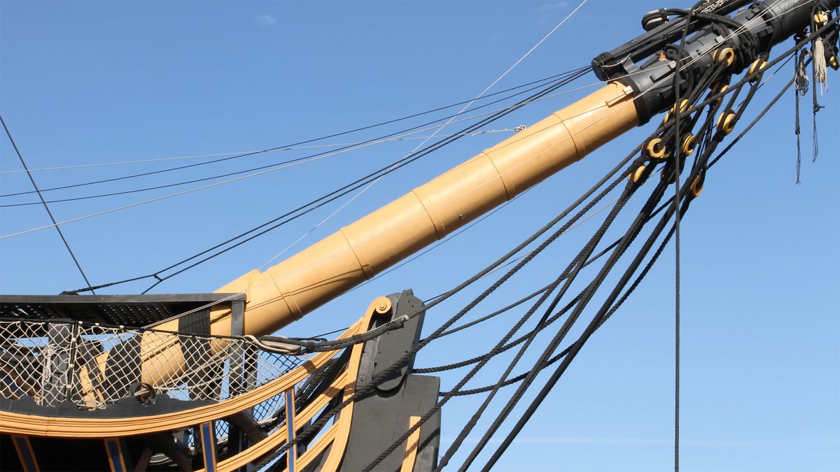
10 hours ago, Justin P. said:
From the VICTORY website:
"HMS Victory is currently undergoing a 13 year, £35million conservation project, with experts from fields such as timber preservation, shipbuilding, rigging, conservation, engineering and heritage. This is an exciting time for the ship. The most obvious sign of the project is that her masts have been temporarily removed, and visitors are also able to see first hand some of the work that is being carried out on board to save HMS Victory for future generations to enjoy."
They don't mince words here, they could conceivably throw some new lines and another layer of paint on her but here is where the two things diverge. The paint will be vetted for interactions with every other element at play and the rigging specially chosen if not completely remade following period appropriate protocols. It is more than a "replace all the rigging" protocol and likely they still choose to retain as much as they can of the original (if any of the original exists).
It seems they classify the parts of Victory on a four-point scale reflecting various benchmarks in her history. With respect to her bowsprit, they note:
- Present at Launch - No
- Present at Trafalgar - No
- Present Pre-1923 - No. Fitted 1936
- Rarity - Some
They note:
By 1936 it was clear that the Victory’s bowsprit, which dated from 1859, was no longer structurally safe. Experts advised that ‘it would appear to have earned its discharge’ and recommended that it should be replaced by a steel tube.
A section of the removed 1859 bowsprit is exhibited in Storehouse 10, at the foot of the staircase leading to the Fore Topsail Gallery.
I believe all the lower sections of Victory's masts are made of steel tube, the same as her bowsprit. Back in 1936, I suppose that was "restoration," rather than "conservation."!
https://www.hms-victory.com/bones/frame?layout=simple&fr=x
(Restoration log of HMS Victory website: https://www.hms-victory.com/restoration-log/preserving-history-hms-victory-through-archives )
Don't get me started on a rant about the US National Park Service's "policy" that the deterioration of ships and buildings "is part of their history" as an excuse to let priceless artifacts rot away, nor the government's budgeting practices that often require five years or more to get major projects approved. The result is too often a total lack of necessary routine maintenance of floating vessels which must be routinely maintained to avoid catastrophic damage, last minute failed attempts to obtain "emergency stop-gap funding" for repairs, or diversion of such funds to other projects if they are provided at all, and the eventual scrapping of the vessels as ultimately "beyond repair." SS Wapama being an example:
https://en.wikipedia.org/wiki/Wapama_(steam_schooner)
https://councilofamericanmaritimemuseums.org/documentation-projects/steam-schooner-wapama/ (with links to full set of lines and construction drawings suitable for modeling.)
https://www.loc.gov/resource/hhh.ca1521.photos?st=gallery (Library of Congress detailed photo set)
https://noehill.com/sf/landmarks/nat1973000228.asp
https://www.sfgate.com/bayarea/article/Lumber-schooner-Wapama-last-of-kind-is-condemned-2371267.php (28 photos prior to scrapping.)
"By 1997, the maritime park's general management plan called for "minimal" measures to slow the Wapama's deterioration, but it added, "The vessel's underlying structural decay will not be addressed." That, essentially, was a death sentence for the ship."
-
Sad indeed. He was one of my favorite modeling authors. Not always an easy read, but his books were chock full of valuable ideas. His Techniques of Ship Modeling is a must-have.
- druxey, mtaylor and FriedClams
-
3
-
6 hours ago, Richmond said:
I am very new to air brushing and have been using vallejos air line of paint, I assumed I shouldn’t thin this paint since it’s designed for air brushing out of the bottle...should I be? I’m not too concerned with money as all of it is cheaper then the cigarettes I used to smoke lol but I don’t like being wasteful.
I didn't say that as the original post indicates, but I'll respond to the question:
That's all a matter of your own judgment. If the paint is being sprayed evenly out of the gun, rather than spitting and sputtering and producing a "splattered" finish, that's how it should be. If the paint isn't coming out so thick that it takes forever to dry or "floods" and starts to run, that's how it should be. If it produces a perfect finish without buildup that obscures fine detail, that's how it should be. If you're happy with it, that's how it should be. If not, it's time to read your airbrushing manual, watch a few YouTube videos, and start experimenting. The problem is more often an incorrect adjustment of your airbrush and you should troubleshoot for that before blaming the paint. Learn what "conditioners" (thinners, retarders, drying accelerators, and leveling agents) are available to you and add those to your arsenal.

Oseberg Ship by KrisWood - 1:25 - Vibeke Bischoff Plans
in - Subjects built Up to and including 1500 AD
Posted
Happened across a Viking ship monograph while doing some quick research on an unrelated ship for a friend.
The Frigate Constitution and Other Historic Ships, by F. Alexander Magoun, S.B, S.M. written in 1927 and republished by Bonanza Books is a book of ship modeling mongraphs of historic ships by a professor at MIT. It's somewhat hard to come by in it's original printings, but there have been many reproductions, some of poor reproduction quality. Get the original edition or the Bonanza reprint, if you can.
One of the featured historic ships is the Gokstad Ship, a Viking vessel excavated in Norway in 1880. The book contains detailed high quality drawings, including construction details, taken from the vessel itself and instructions for building a model of it. There is also a long and detailed description of a "Viking funeral" as found upon the excavation of this vessel. You'd probably find it fascinating and a helpful supplement to your research and plans collecting.