


Stuntflyer
-
Posts
1,140 -
Joined
-
Last visited
Content Type
Profiles
Forums
Gallery
Events
Posts posted by Stuntflyer
-
-
Thank you all for the comments and "Likes"
Sure, Rusty! I'll make you as many as you want if you will do my rope coils.
")
Mike
- Ryland Craze, Canute and Jack12477
-
 3
3
-
Really beautiful, Chuck! A wonderful build log packed with lots of useful information. You are a great model builder and I'm sure that the barge will be another beauty.
Mike
- Ryland Craze, Tigersteve, mtaylor and 2 others
-
5
-
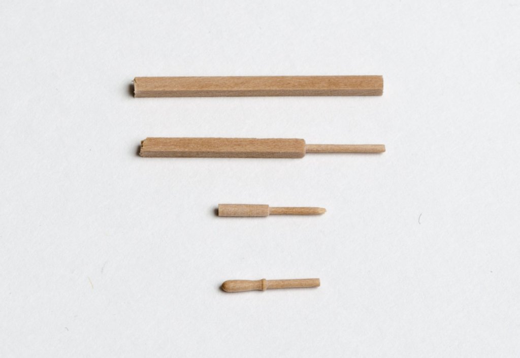
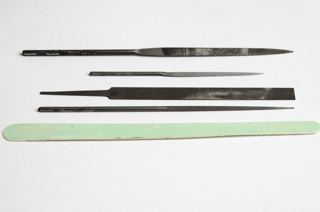
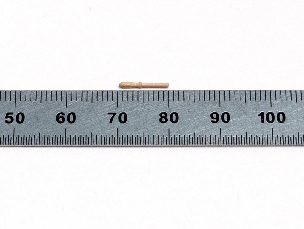
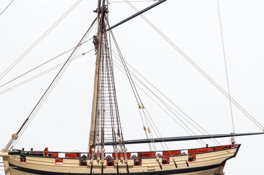
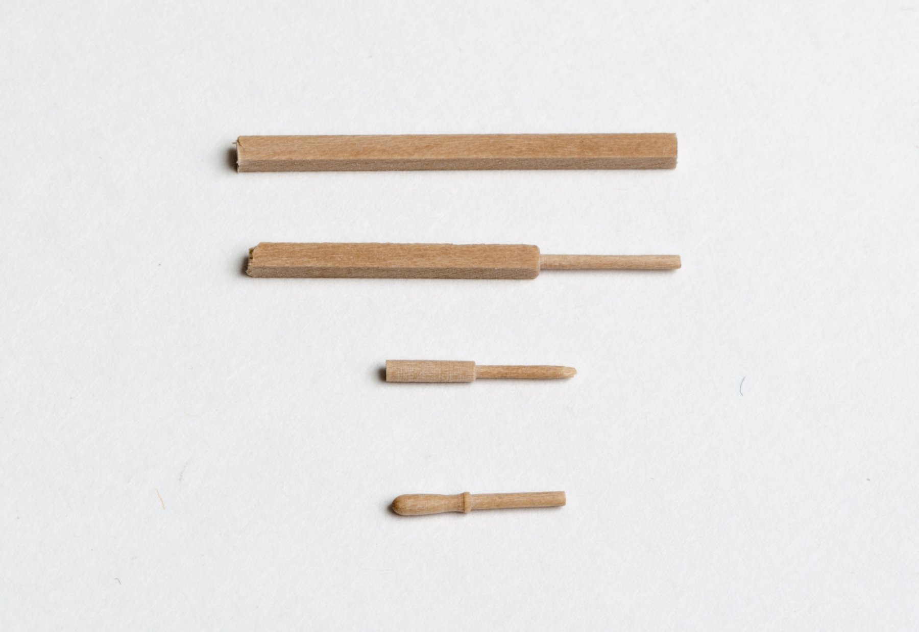
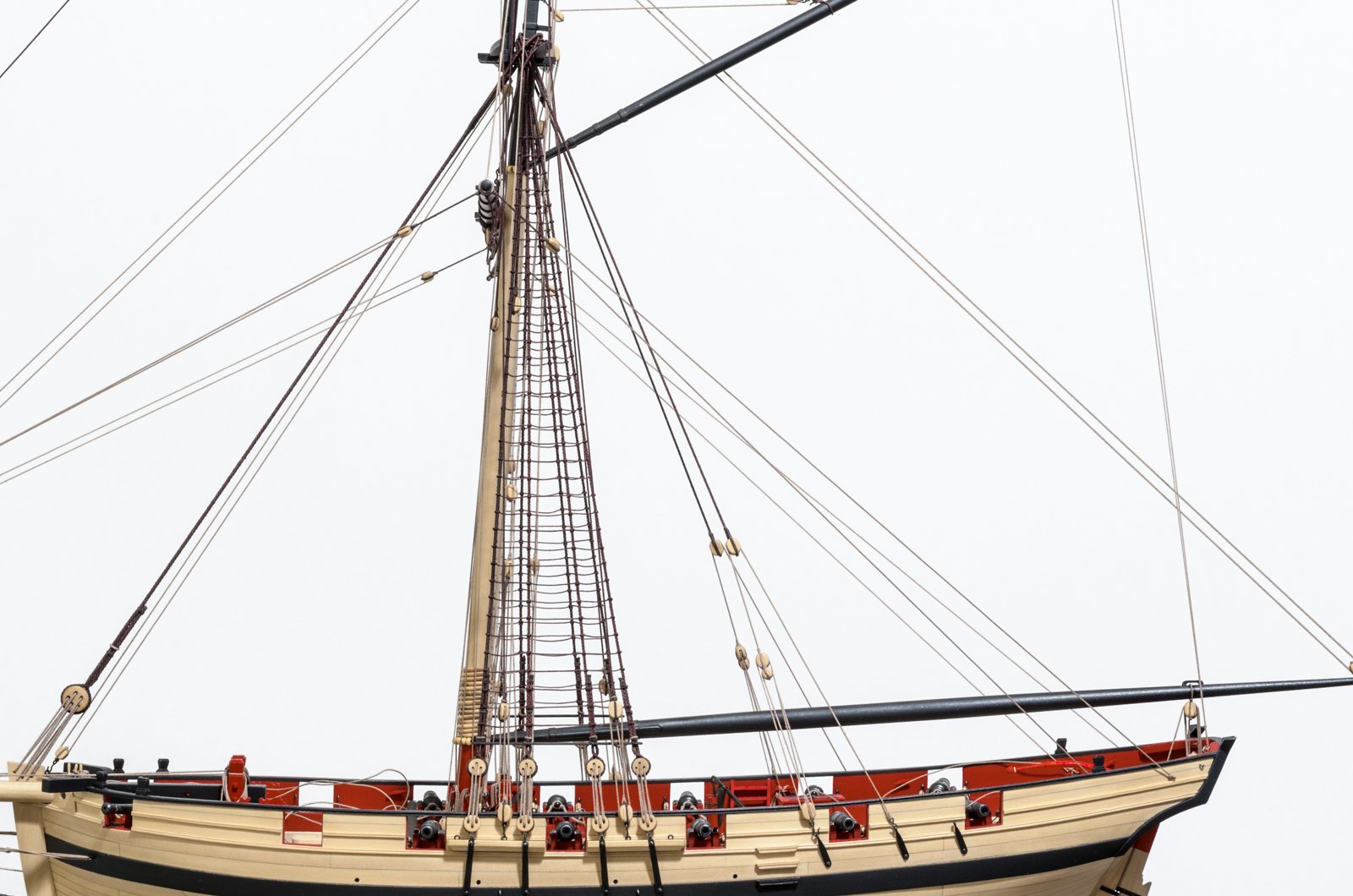
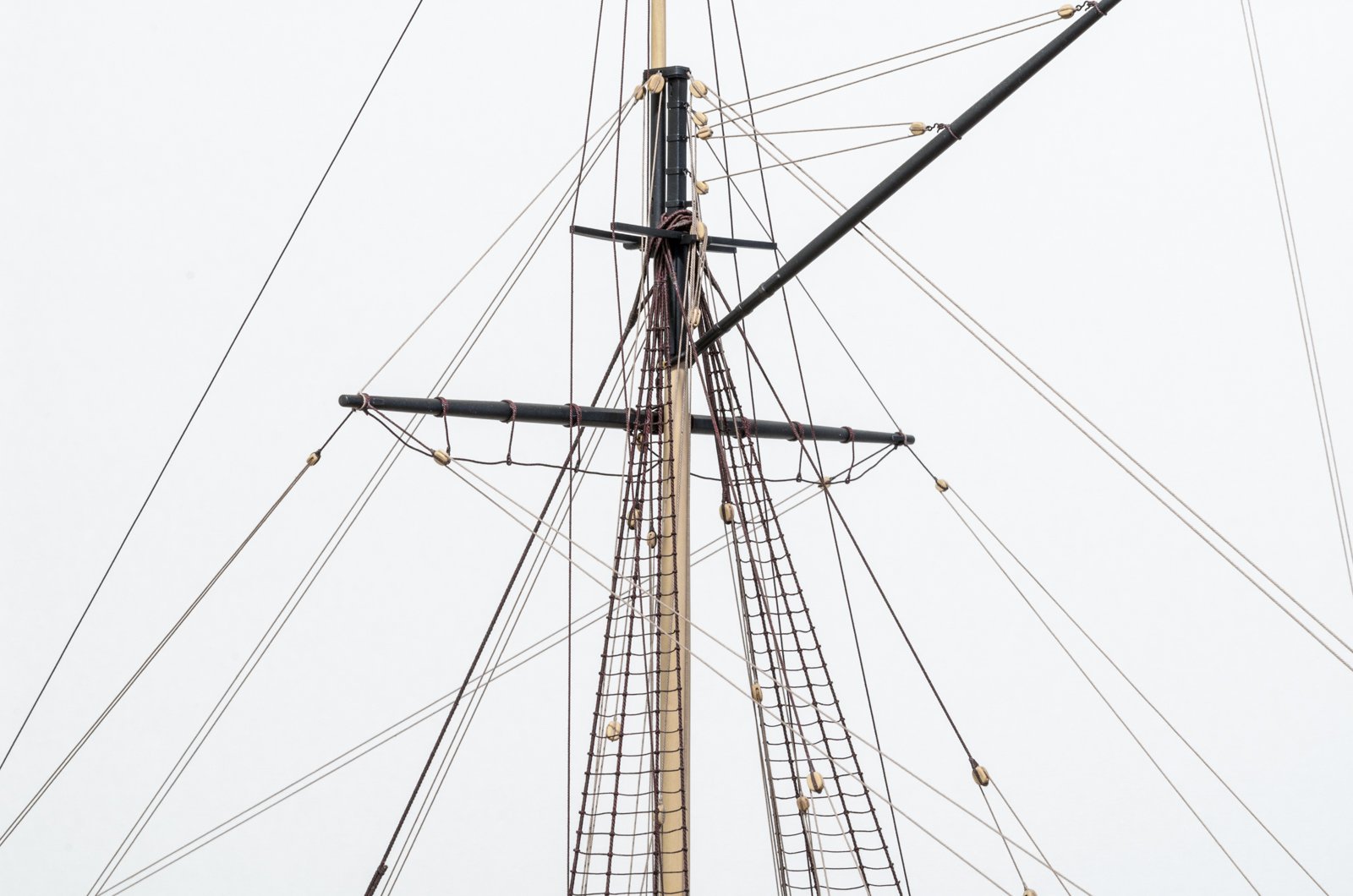
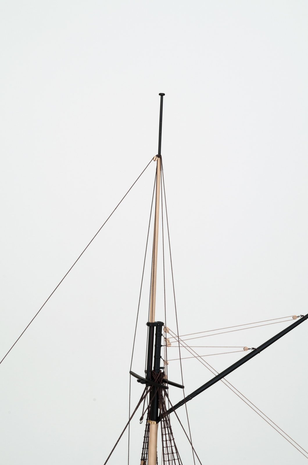
While working on the topsail yard, I noticed that I needed a few more belaying pins. These were made from 1/16" square boxwood strips and the Dremel rotary tool. Using a 1/16" collet, the bottom end of the pin was reduced to .032" (1 1/2" scale). After cutting the handle of the pin to the correct length, the bottom end was inserted into a 1/32" collet and the pin was reduced to .045 (2 5/32" scale) From here the handle was easily shaped, and the bottom was trimmed off. Final length = 18" scale.
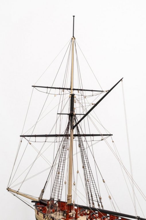
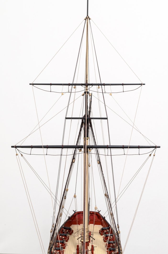
The topsail yard is completed and all lines are belayed. I still need to trim the lines and add the remaining rope coils.

- KenW, amateur, Pete Jaquith and 29 others
-
32
-
Thank you, Johann, Christian, Maury, Nils and Thomas for the wonderful comments and for the "Likes". All very much appreciated!
Mike
- Mirabell61, mtaylor and Canute
-
3
-
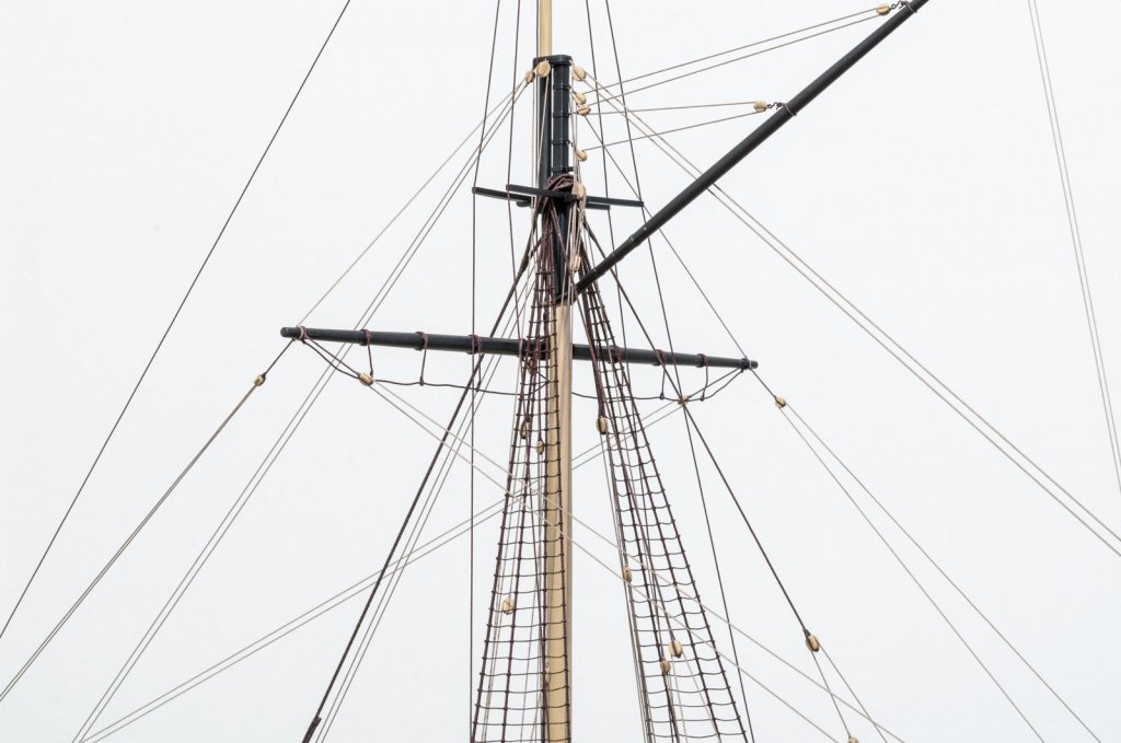
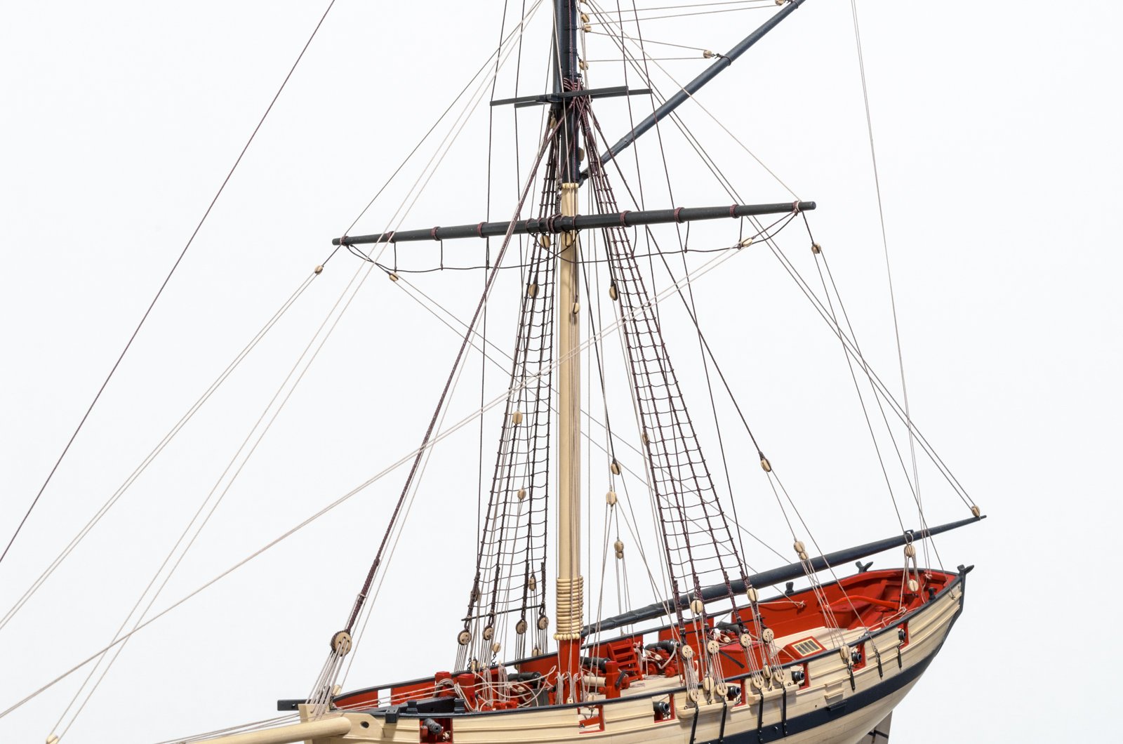
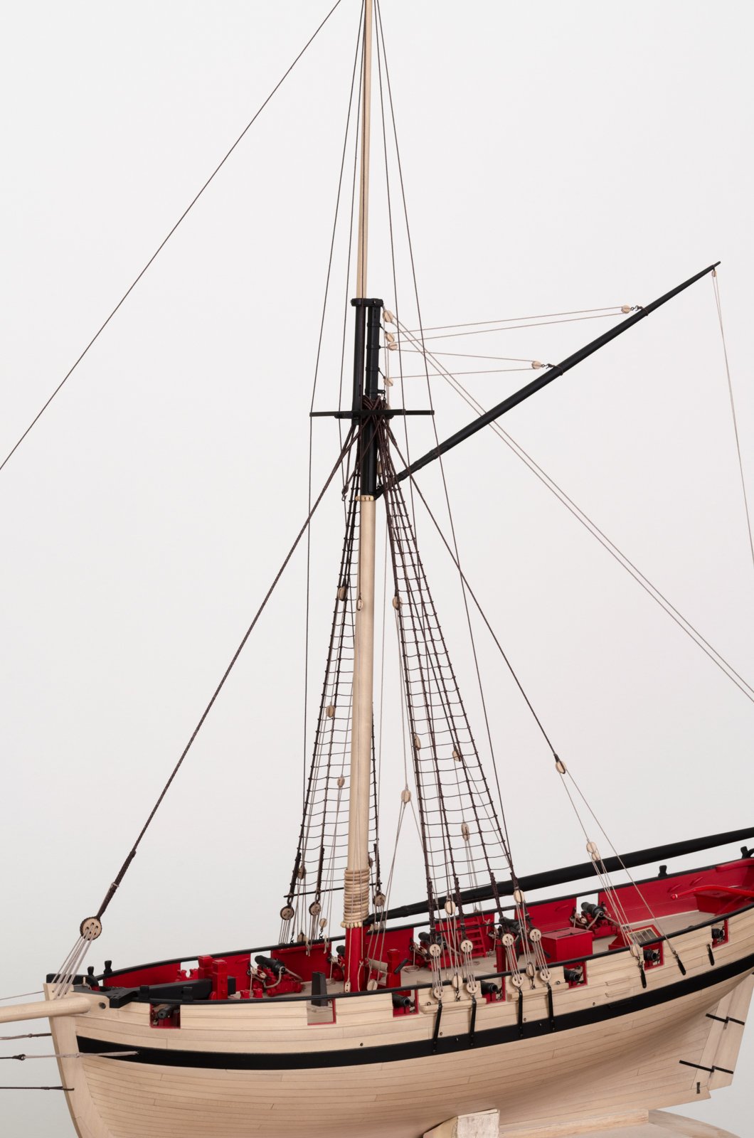
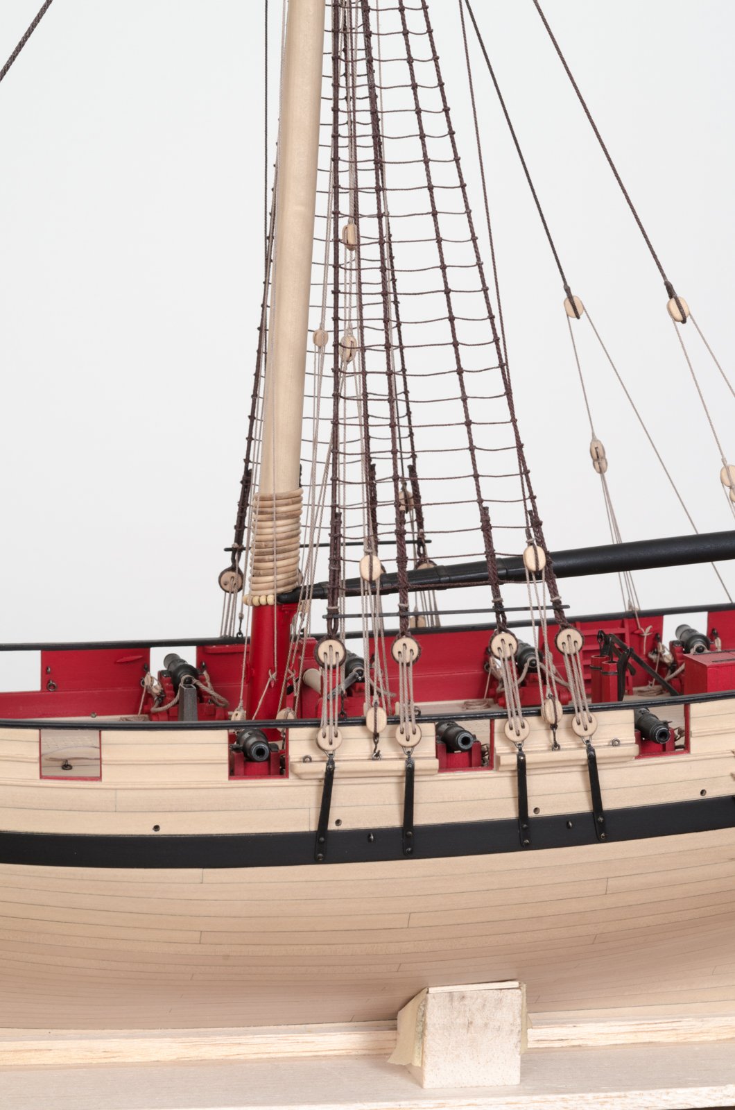
Progress has been slow lately with the yards, mainly due to my putting off doing them. However, once I got started things went smoother than I originally thought and it was good to have Chuck's build log and plan detail as a reference. The lower yard rigging is done with the exception of trimming a few rope ends and adding coils. I'm going to tidy up the stirrups and horses after the topsail yard rigging is completed. My plan is to do that with the aide of some acrylic matte clear finish.


Mike
- druxey, Dubz, AnobiumPunctatum and 19 others
-
22
-
Aha! Thanks for the update, Chuck.
Mike
- Nirvana, Canute, popeye the sailor and 1 other
-
4
-
14 hours ago, Chuck said:
I will have plenty of more detailed images of the rigging once Mike drops by with his camera. He doesn't know this yet but I plan on asking him to help me photograph this stuff. Photographing rigging with a point and shoot is impossible.
I'm ready when you are, Chuck.
Mike
- Jack12477, Ryland Craze, mtaylor and 2 others
-
5
-
Thanks guys! Yard Rigging is next, though I only have a general idea on how to do them. Guess it's time to do some research. Stay tuned!
Mike
- Ryland Craze, mtaylor, Tigersteve and 3 others
-
6
-
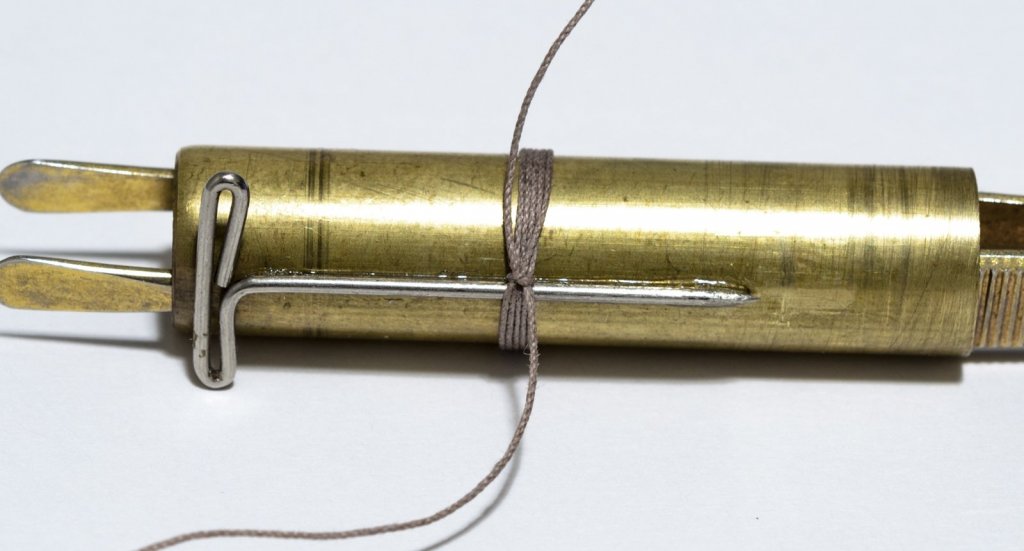
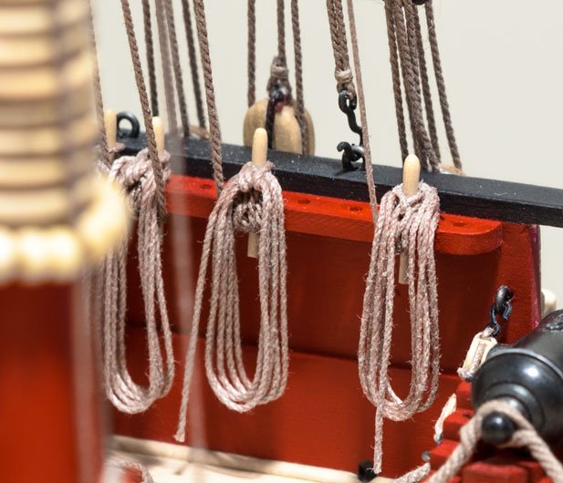
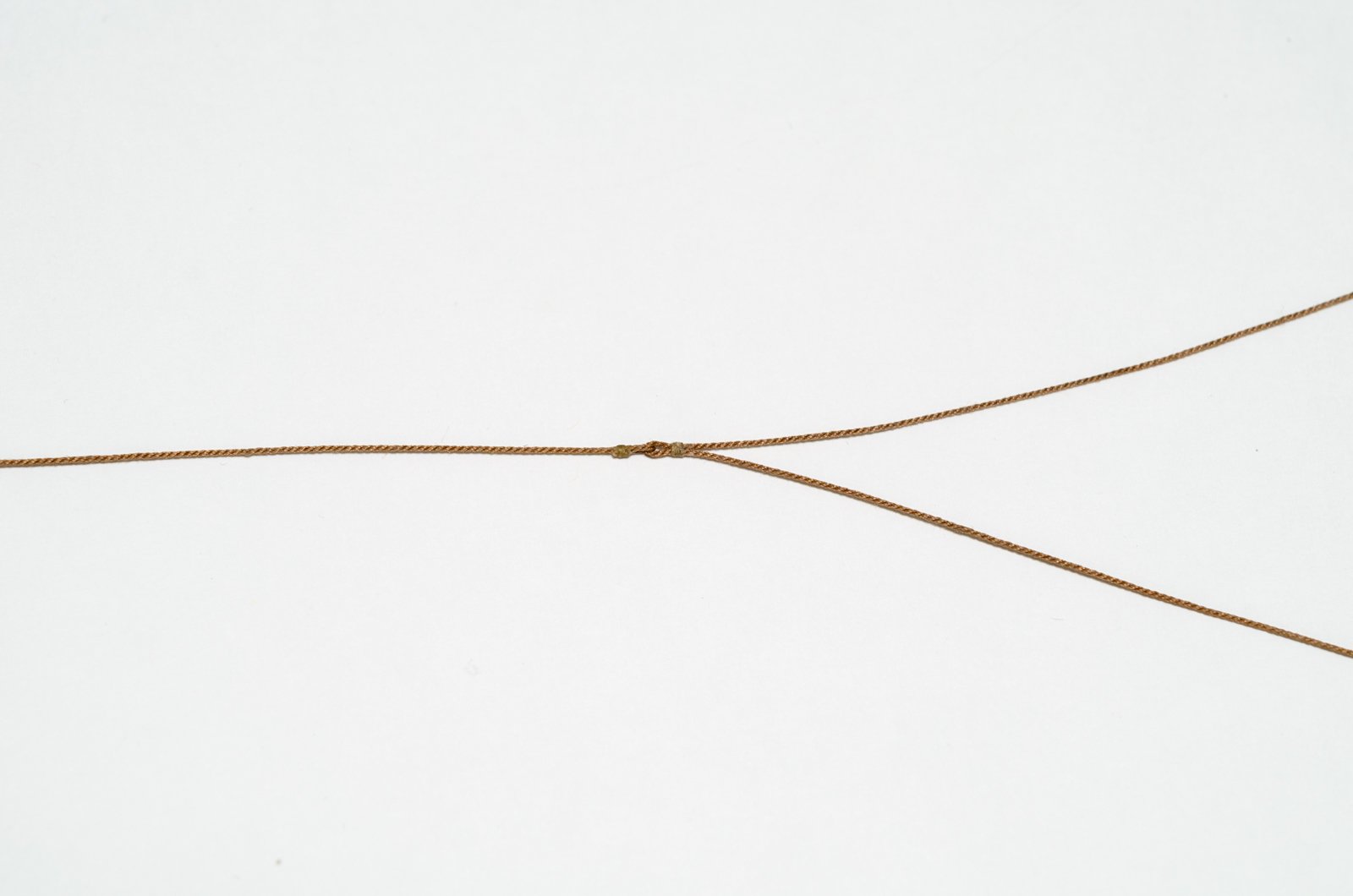
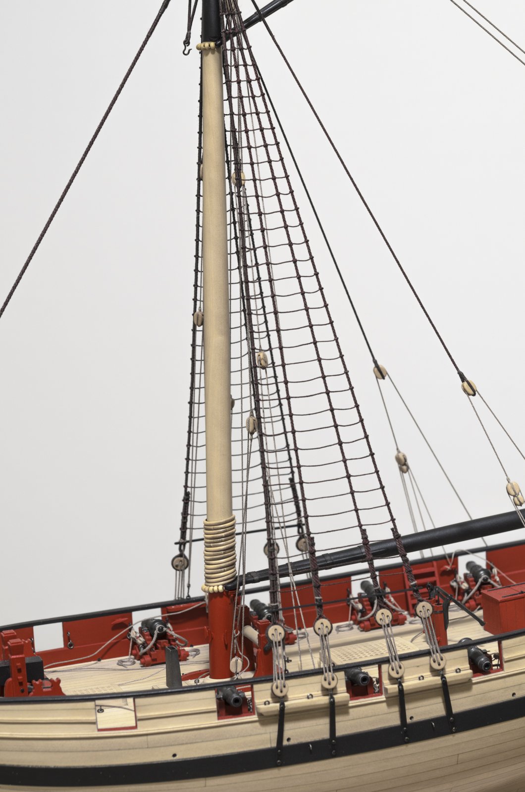
Well, its been an interesting week. The rope coils that were needed are now completed. I can see that this is an area that could use some further refinement and I will try to do that as the rigging continues. I tried to follow chuck's method of doing them, but came up a little short, I think. Also, I would like more rope available for re-tensioning should the need arise. In the end I came up with a different way that gives me a little more flexibility. Unfortunately, none of it can be used on the completed coils. Some of the photos are macro shots so the detail can be brutal. I referenced David Antscherls TFFM vol.4 pg 103 for making the rope coils.
The rope is wrapped around brass tubing of appropriate diameter. The pin makes space to pass the rope around the coil. A half hitch and a drop of glue secures things.
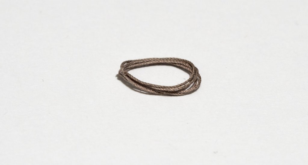
The original coils were done like this. The loop that goes over the belaying pin is one of the coil loops pulled up short and wrapped around the upper coil.
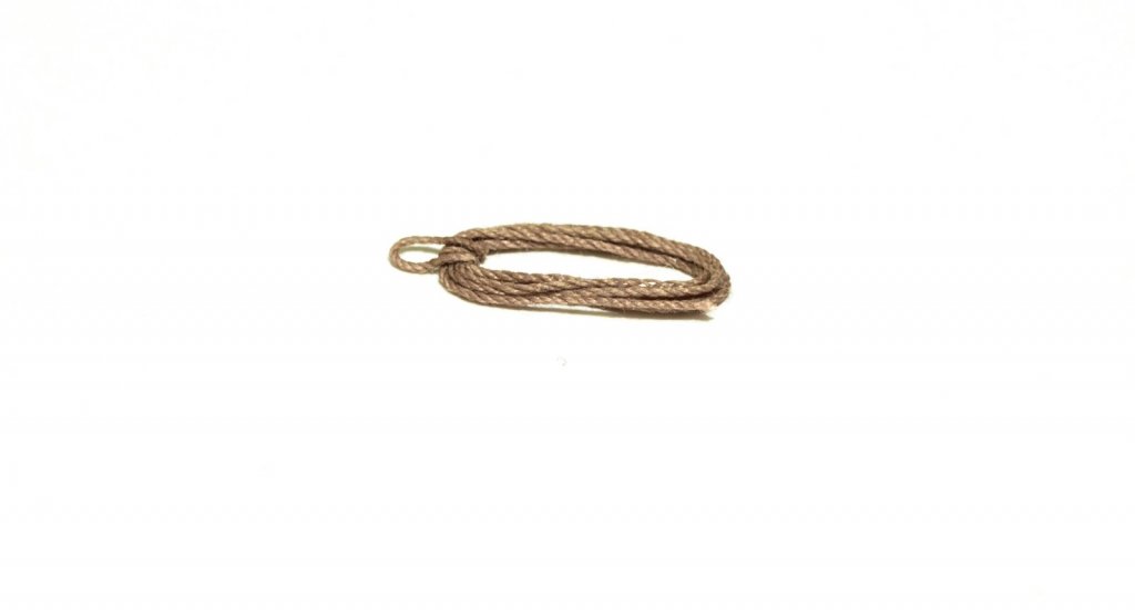
With the new technique the loose ends are cut off flush to the knot.
The way I did the completed rope coils can be seen on the left. The end of the rigging line was belayed, cut short and glued under the pin rail. The coil was then placed over the belaying pin. To demonstrate what I came up with afterwards I'll be using a free pin rail position on the right. Honestly though, I can't help but think that this has already been done. The rigging line is first belayed around the pin. Although not fully seen here, the blue painters tape was wedged behind the pin and pushed down to hold the rope while belaying. The free end is left long.
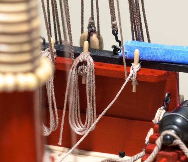
The rope coil was placed over the belaying pin with the knot behind the pin. It was then stretched with a 1/8" drill and given a coat of Badger "Clear Matte" acrylic.
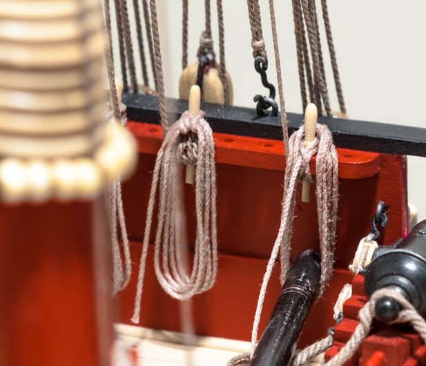
This is the end result after removing the drill, hitching the loose end to the belaying pin and cutting the fall. Lots of rope to hold onto should the need to re-tension arise.
Mike
- shipcarpenter, KenW, Ryland Craze and 22 others
-
25
-
Tom, Michael and Albert, Thank you!
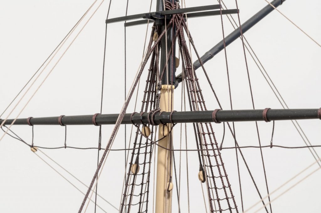
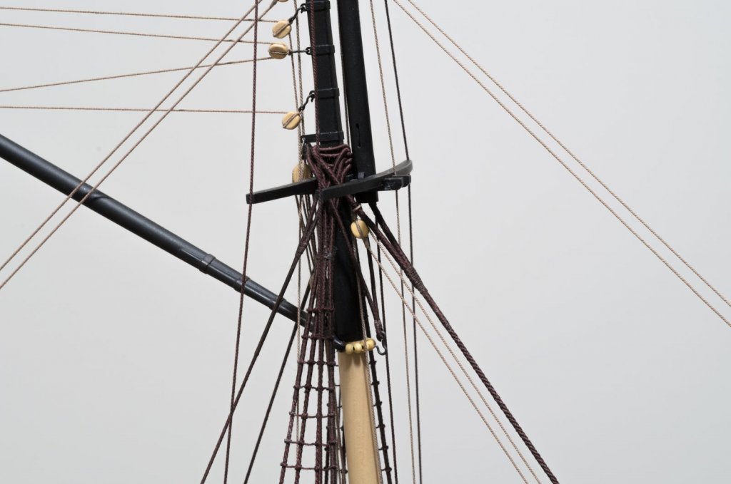
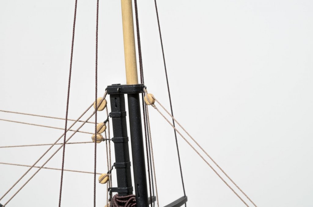
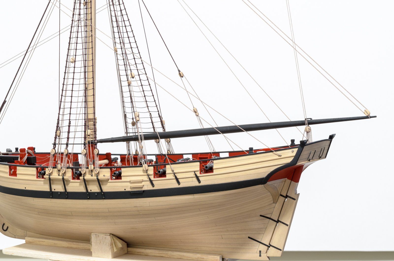
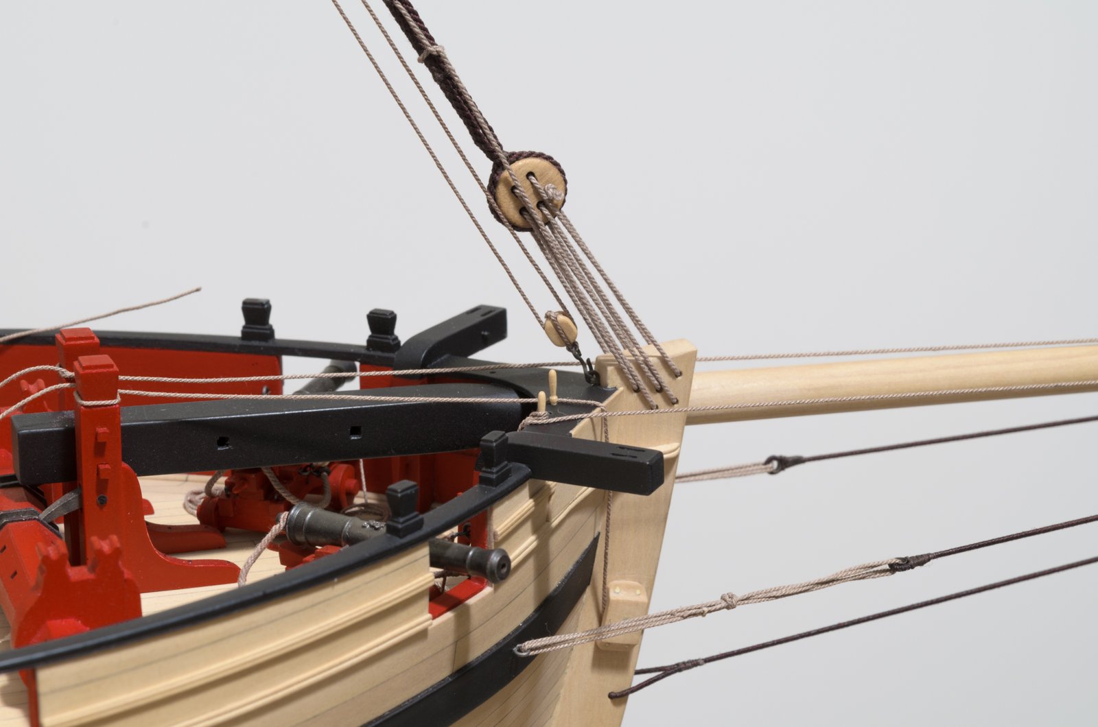
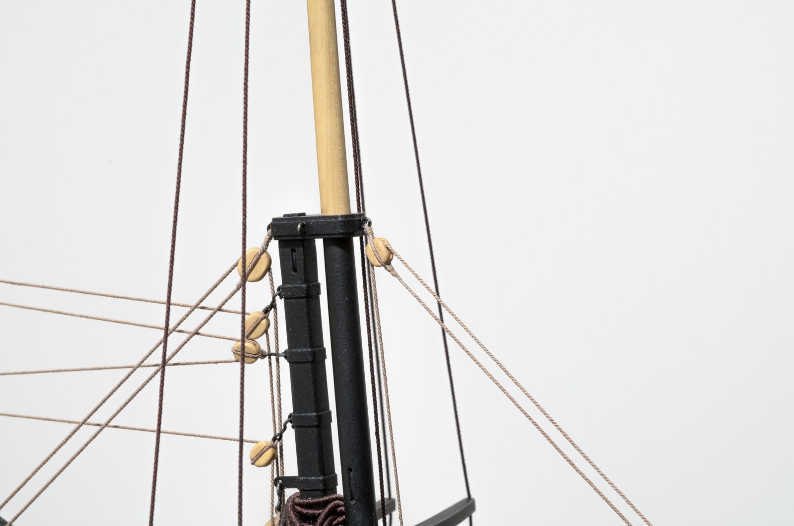
Work continues with the foresail halliard. There is a 24 gauge eyebolt located on the cap rail and just aft of the stem. Not that it's hard to do, but I can see where one might want to place it early on before the rigging is started. The block located behind the crosstree wasn't difficult to place, but care has to be taken not to bang into the other rigging already there. Chuck noted that it has to be placed so the rope falls behind the lower yard to a cleat on the lower mast.
Time to tighten things up and get to those rope coils I have been avoiding. . .

Mike
-
Looks very nice, Erik. A major hurdle cleared.
Touching up never seems to end, so there is plenty of time for that.
Mike
- MikeB4, Ryland Craze, mtaylor and 4 others
-
7
-
-
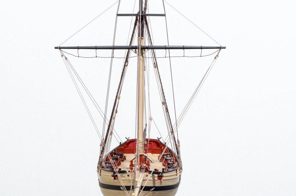
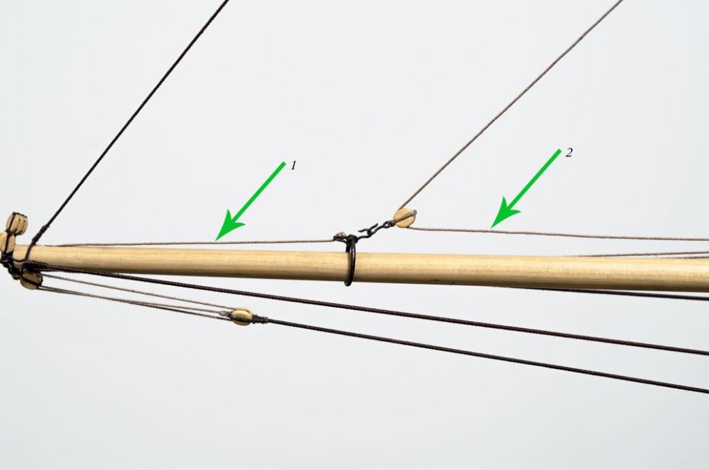
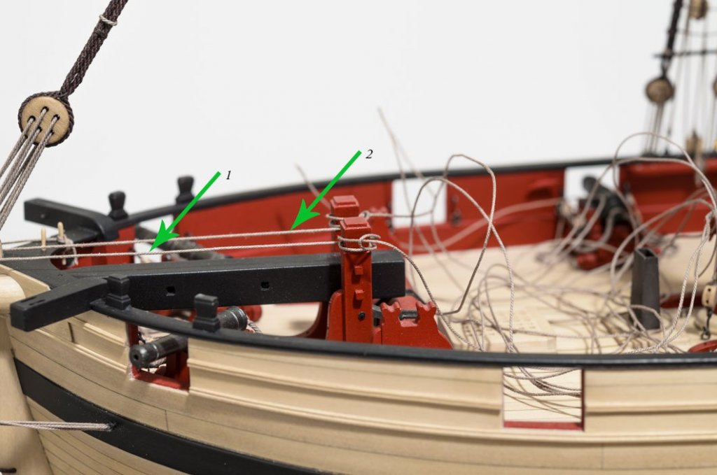
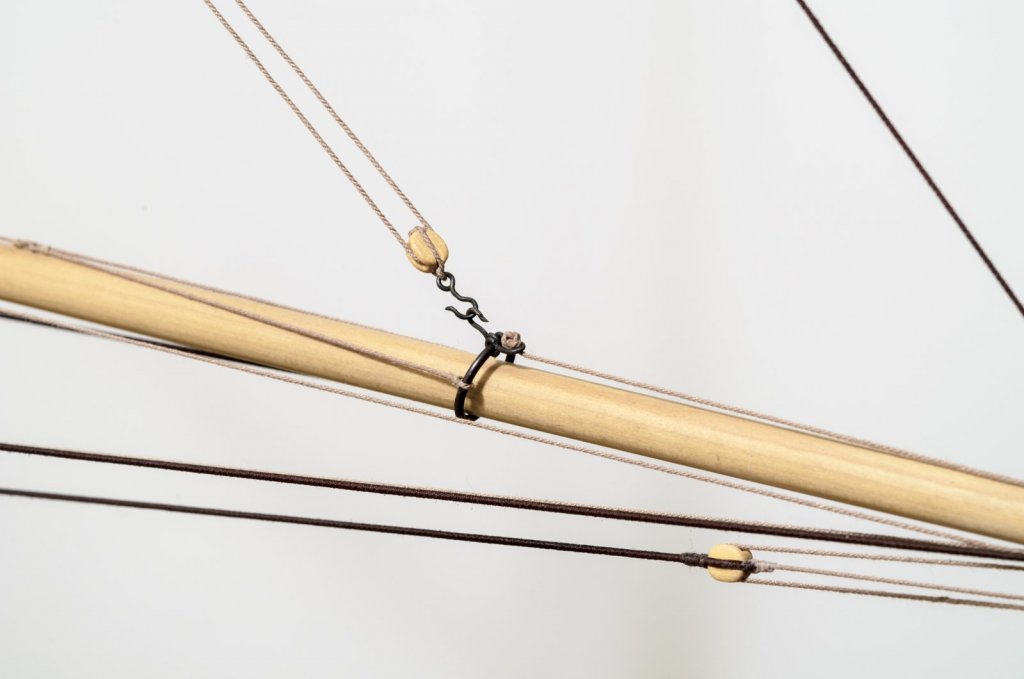
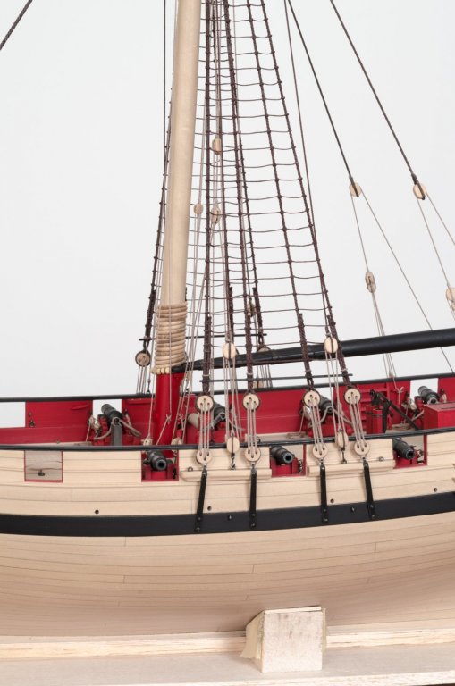
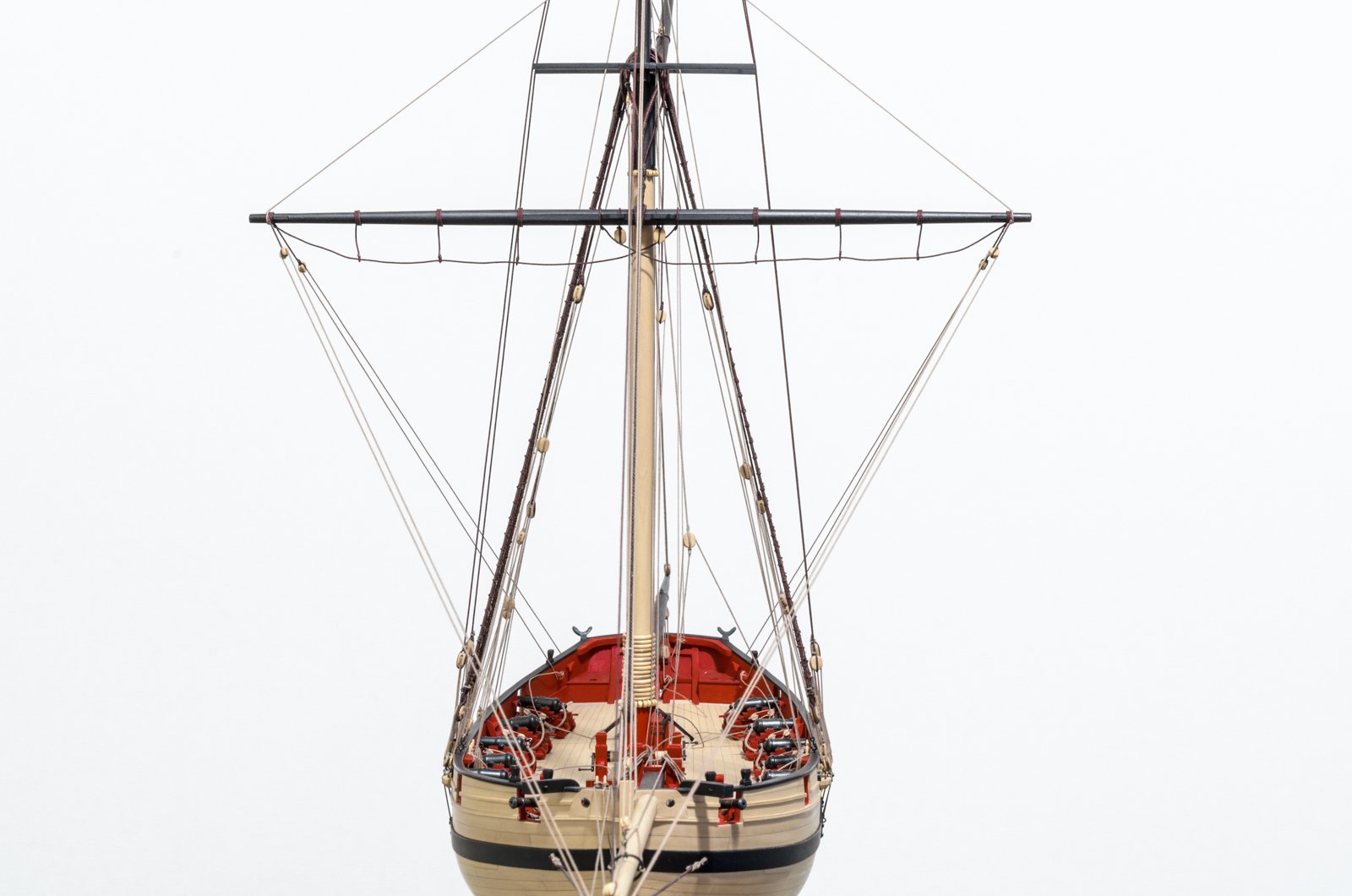
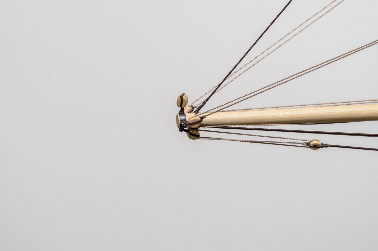
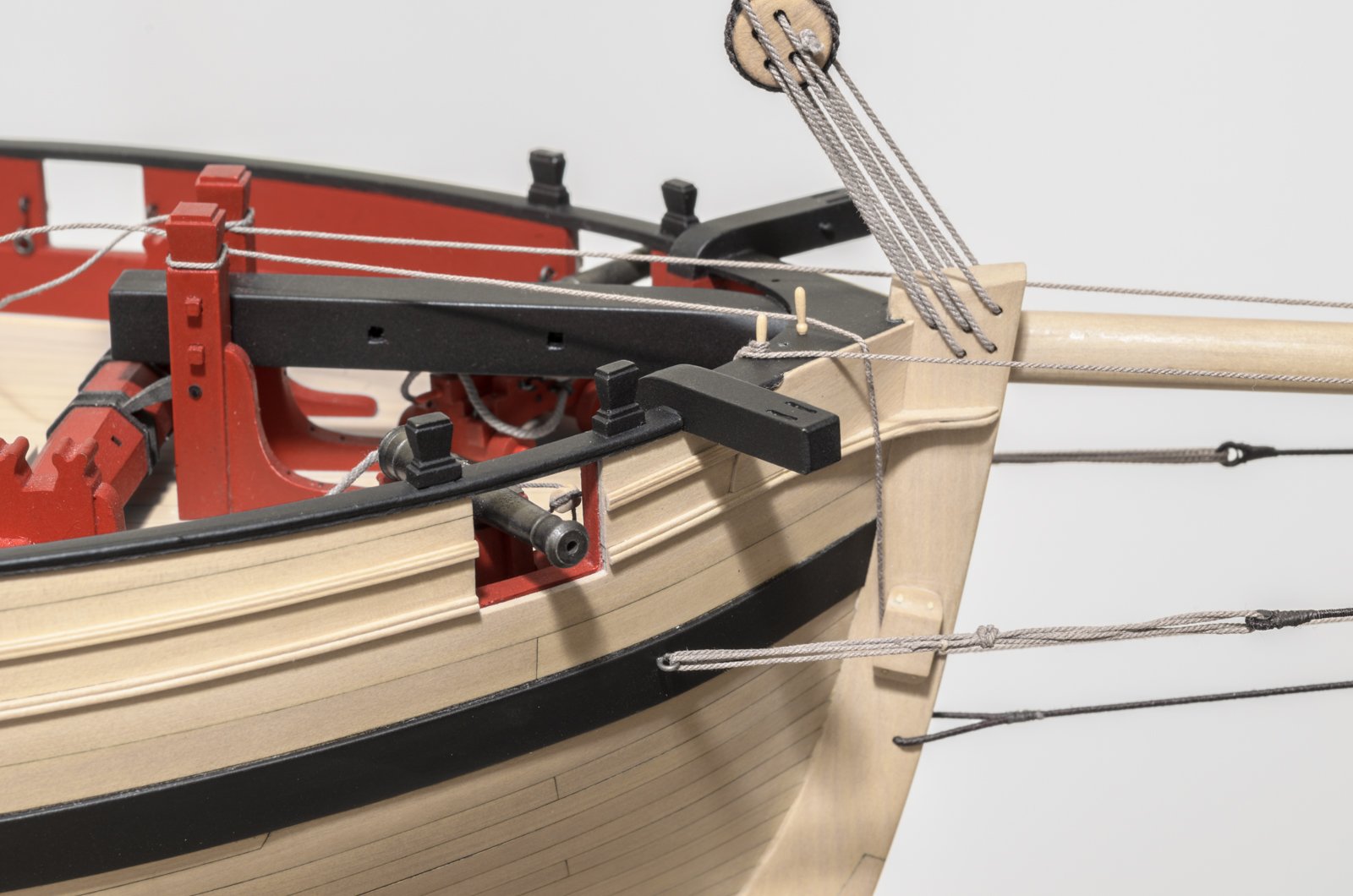
Today, I started the running rigging with the jib halliard and related components. The traveler ring, was made by Chuck and is available on his website. I decided that stabilizing the traveler ring was key to making it all go smoothly. The photos below show the steps taken to achieve this. Note that the jib halliard #2 is temporarily wrapped around one of the bowsprit bitts instead of being fully rigged through the block at the mast head. That will come later after the jib inhaul is completed. The jib outhaul #1 is routed correctly.
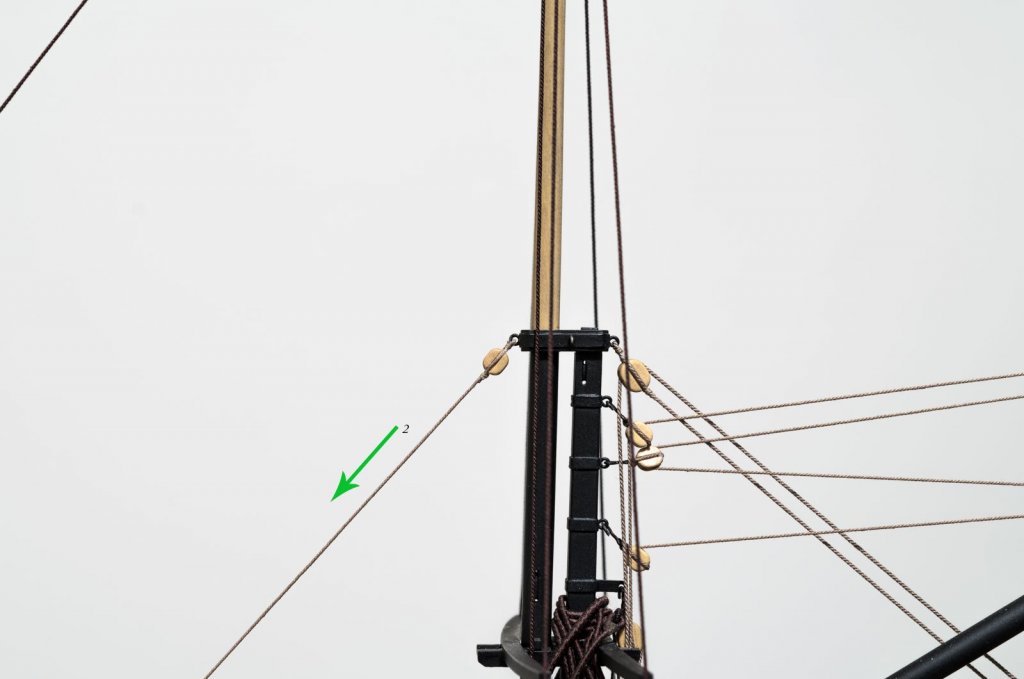
With the traveler ring stabilized I made the jib inhaul.
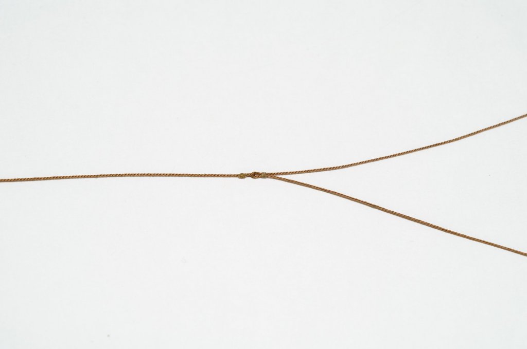
Lastly the inhaul was seized to the traveler ring and the jib halliard was routed correctly.

Hope this all makes sense. .
Mike
- KenW, John Cheevers, Mike Y and 28 others
-
31
-
Dirk, Rusty, thank you for the kind words, and for all the "Likes"
Mike
- mtaylor, Ryland Craze, Jack12477 and 1 other
-
4
-
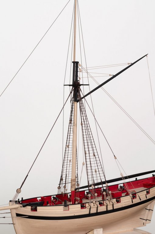
Well, I have finally made it past the standing rigging. I recently noticed that the cleats going around the lower mast are evenly spaced, just not in the right starting position. They all need to be shifted 5-10° in one direction to match the plans. I don't see this as anything to be concerned about, but I will leave the top mast stay tackle long, should I need to move it to another cleat later. It's impossible to take the photos the way I want to show them, that is the entire image, full size and high resolution. Can't have everything, but hopefully you will get the idea.
Mike
- oneslim, Tigersteve, russ and 22 others
-
25
-
Hi Rusty,
I glad to see your making some nice progress again. You might find that the pin rail between the catheads will have to be raised, virtually level with the top of the caprail, in order to clear the bowsprit. Check out Chuck's third photo in post #910. I had to do the same on mine.
Mike
- Ryland Craze, druxey, mtaylor and 4 others
-
7
-
Erik,
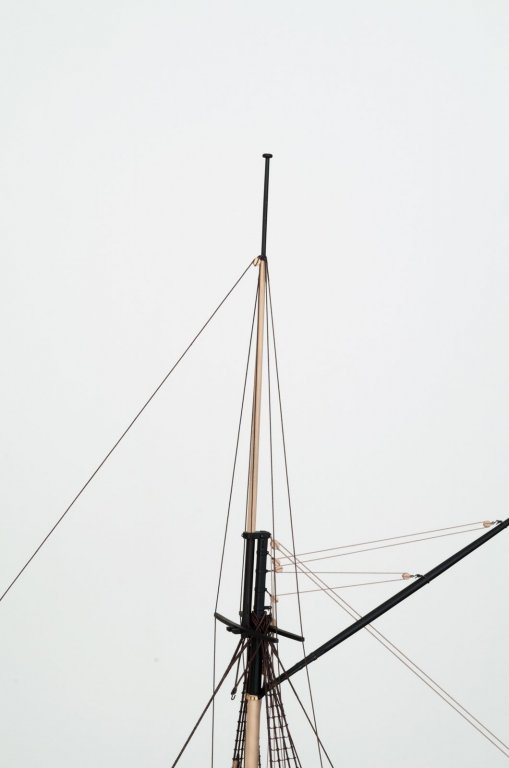
The topsail yard was reduced approx 1 1/2" (actual) and the lower yard was reduced by approx 1 13/16" (actual) . As to why they where drawn longer on the plans, I really can't say.
Mike
- Canute, Ryland Craze, Captain Poison and 1 other
-
4
-
Hello everyone,
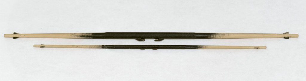
I've completed a few projects ahead of finishing up the standing rigging. One being the repainting of the workroom and the other being the necessary shortening of the two yards, as per Chuck's instructions. No doubt he will have the drawings and related comments available when he has time. I could have made all new ones, however I wasn't really happy with the idea having to do that. Since the stock thickness remains the same for both. I just shortened them and re-tapered them to the proper spec with the use of a hand drill. The lower yard needed new sheaves and there was just enough length available to allow for this. I left them unpainted so you can see what they look like at this time. I was able to salvage those pesky to make stops as well.
Mike
-
-
-
-
-
Erik,
I would not do it that way. Gaps will remain gaps no matter how much you try and force the wood into place. This is especially true since boxwood is not going to conform to variances in shape beyond a certain point. Take your time to get a press fit, though not too tight. The glue will swell the wood slightly and you definitely want the wood to go into the space as far as possible. I would only bevel the wood ever so slightly, Too much and there is a risk over thinning the edges during final sanding. You might end up test fitting numerous times in order to get it right. However, I think that the process will go quicker than you might expect.
Mike
- Tigersteve, Nirvana, Maury S and 6 others
-
9
-
Hey Mike.
I have no doubt that you will find this to be an interesting build. Can't say much for the poor Britannia castings, but those can be replaced with wood. Follow Chuck's instructions and it should go smoothly for you. Any questions, please don't hesitate to ask.
Mike
- MikeB4 and Knocklouder
-
2


Halifax by rafine - FINISHED - The Lumberyard - 1:48 - semi-scratch schooner
in - Kit build logs for subjects built from 1751 - 1800
Posted
Nice progress, Bob! It looks like planking that bluff bow might have been a bit challenging?
Mike