Beef Wellington
-
Posts
2,249 -
Joined
-
Last visited
Content Type
Profiles
Forums
Gallery
Events
Everything posted by Beef Wellington
-
 Looks great Rob. Did you end up pinning the rails? As you say, these look pretty long so are maybe less prone to damage, and with the trip piece above also helping push back against any strain from the rigging you are probably in good shape. Must be nice not to have to worry about any armament 🙂
 -
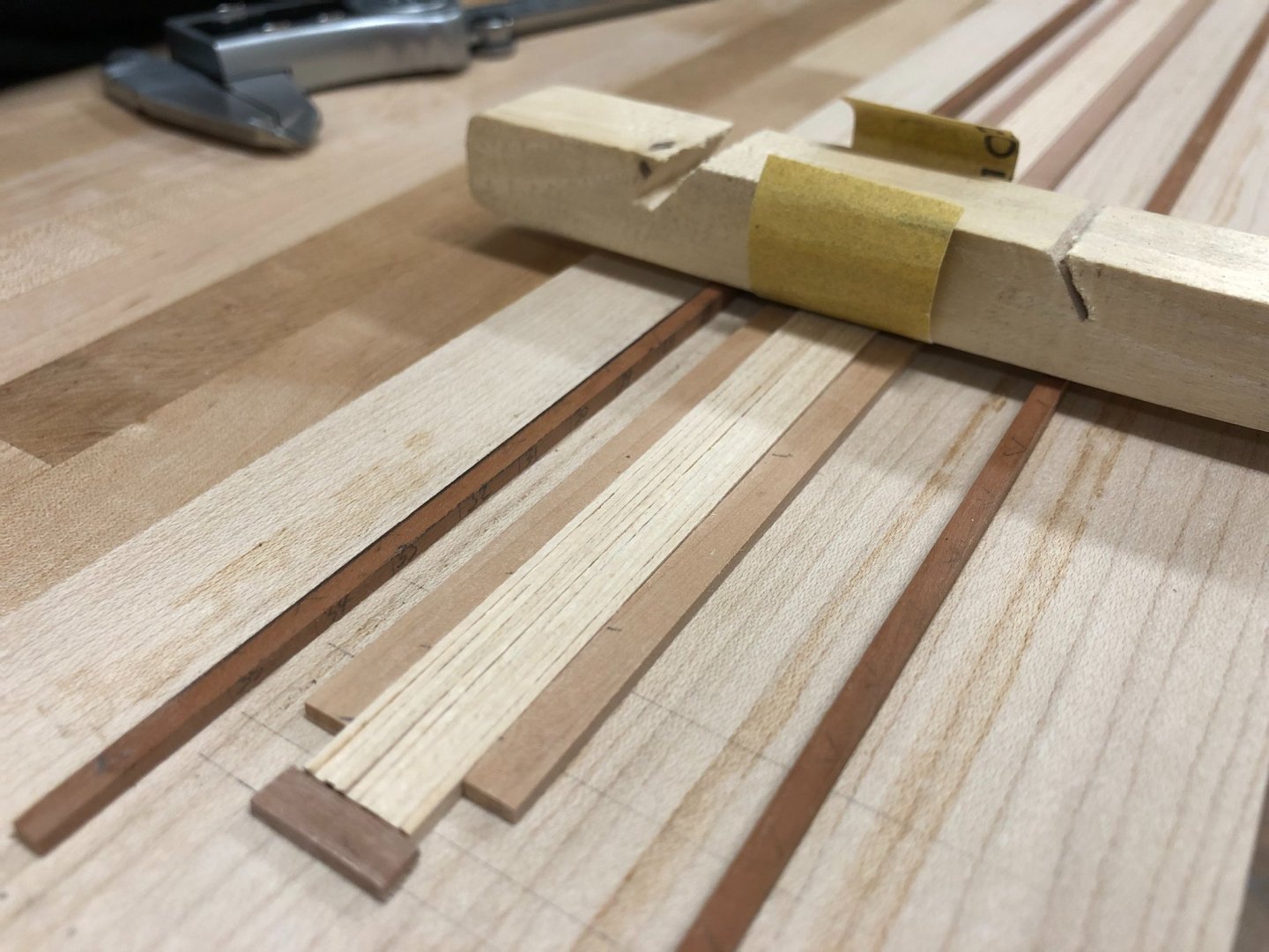
@ Mike - no not officially an engineer, but my brain does work that way....am a physicist by education, and have played a little with battlefield engineering. Up to this point, its been possible to get by just by look and feel, and the philosophy of thinking ahead and not sweating the small stuff 🙂. This task just required more planned precision. BTW - you can never have enough serving on a model if you have the patience for it. Hopefully this photo makes the jig operation clearer (I left the tape off the outside guide templates for clarity). The fine sandpaper shown is around 0.2mm thickness which would pretty much be offset by the electrical tape thickness. (0.2mm plank width variance would add up to a 4mm problem per side, so it adds up quickly)
-
Thanks Rob, you did such an excellent job on Ethalion that its a hard act to follow, but gave me no reason to hold back 🙂 I'm hoping the planned widths are sufficient to at least get started with a reasonable degree of confidence. Once planking starts to approach the planned waterway then I suspect it will then be possible (and necessary) to tailor more manually. Will also leave off installing any waterway planks until necessary as that should also allow some fine tuning.
-
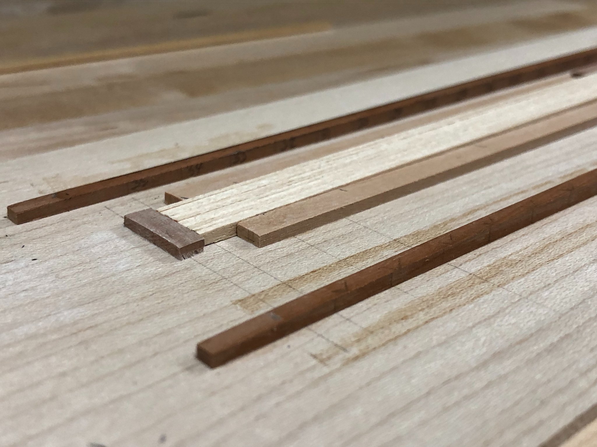
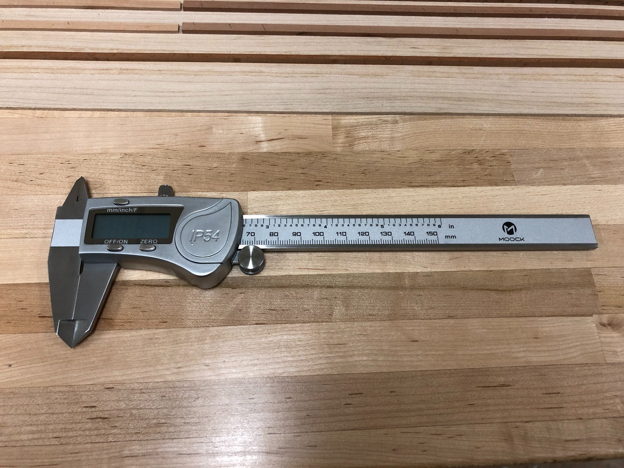
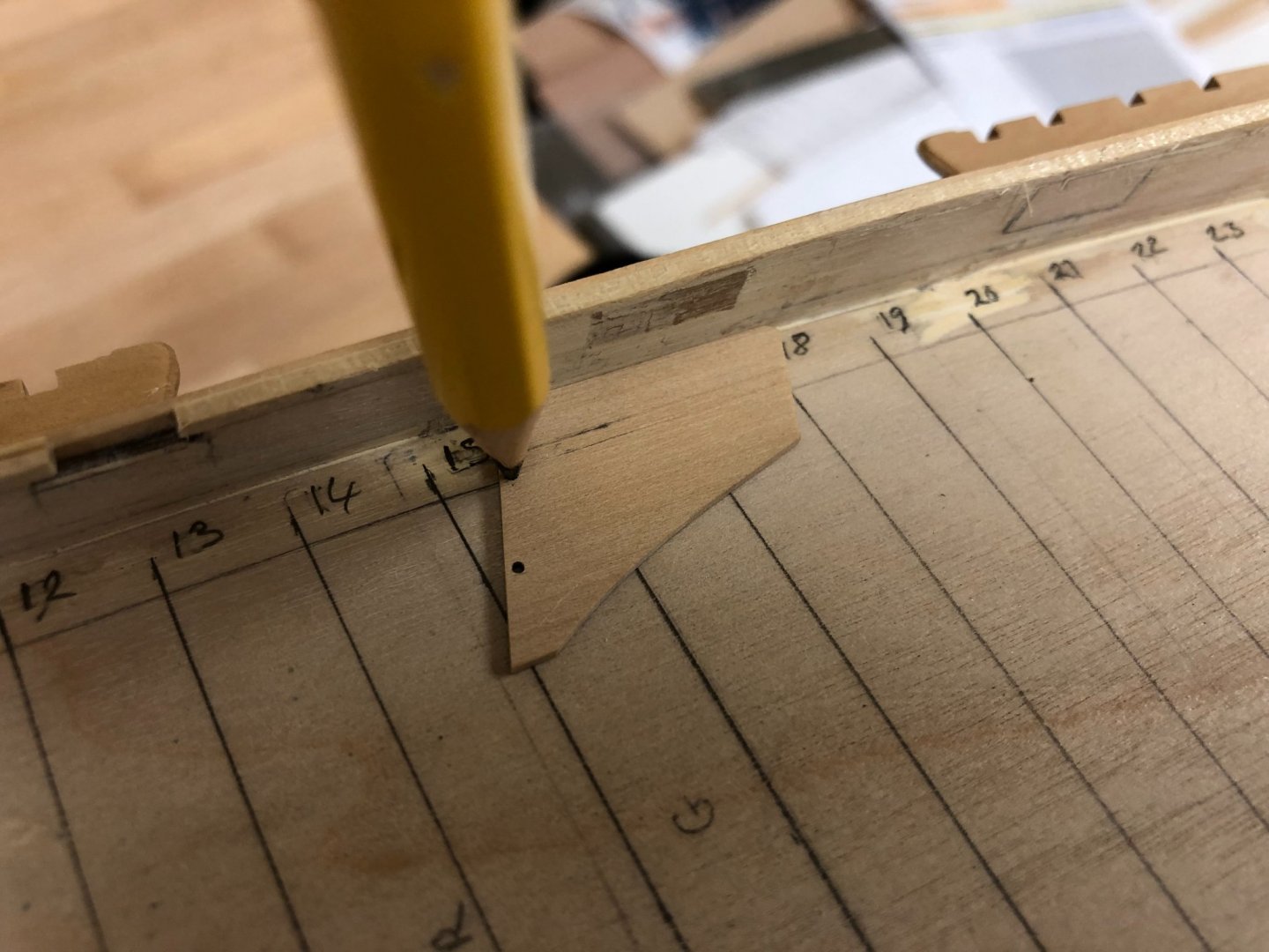
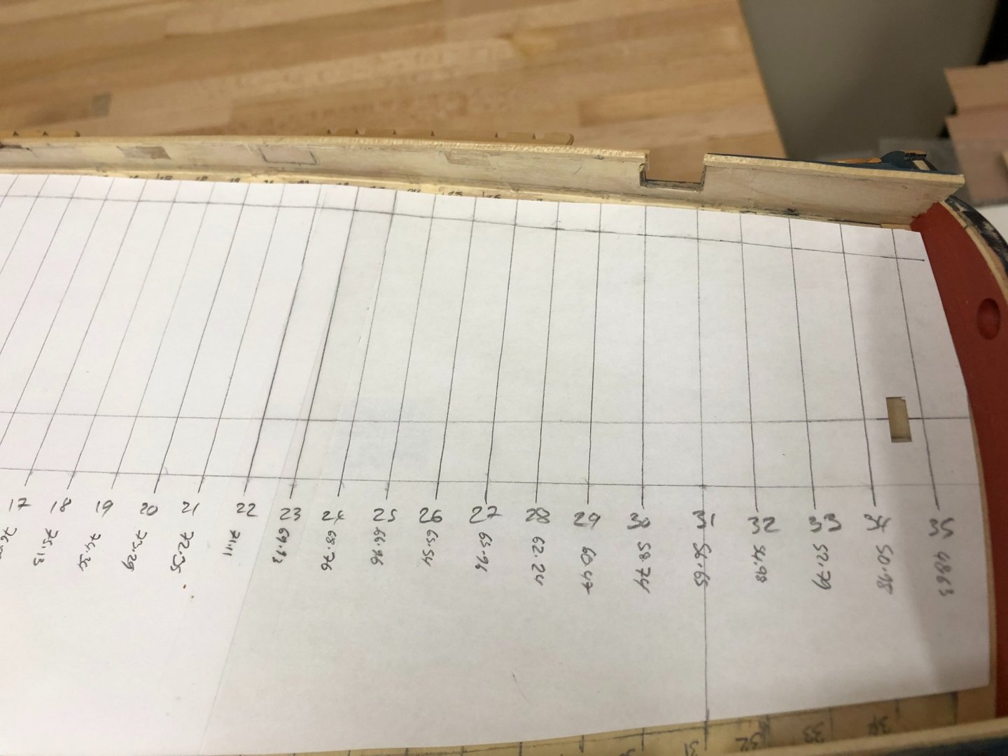
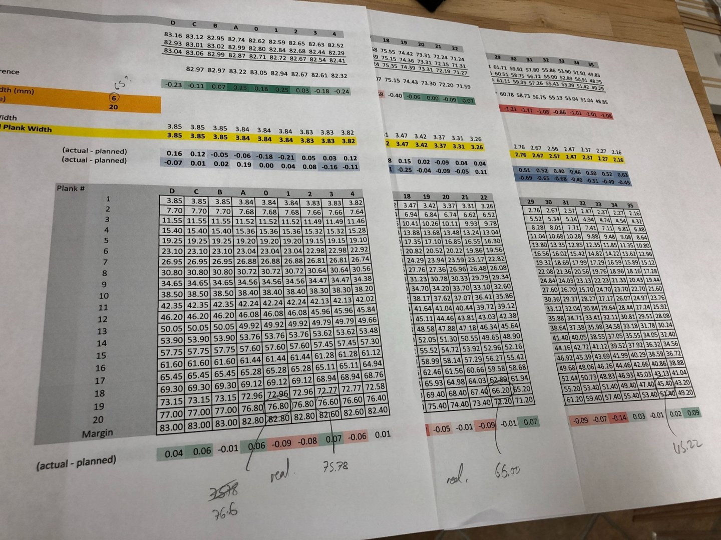
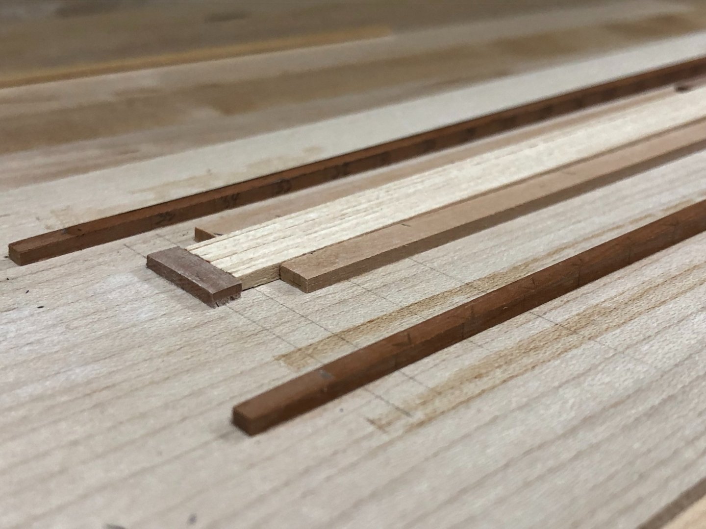
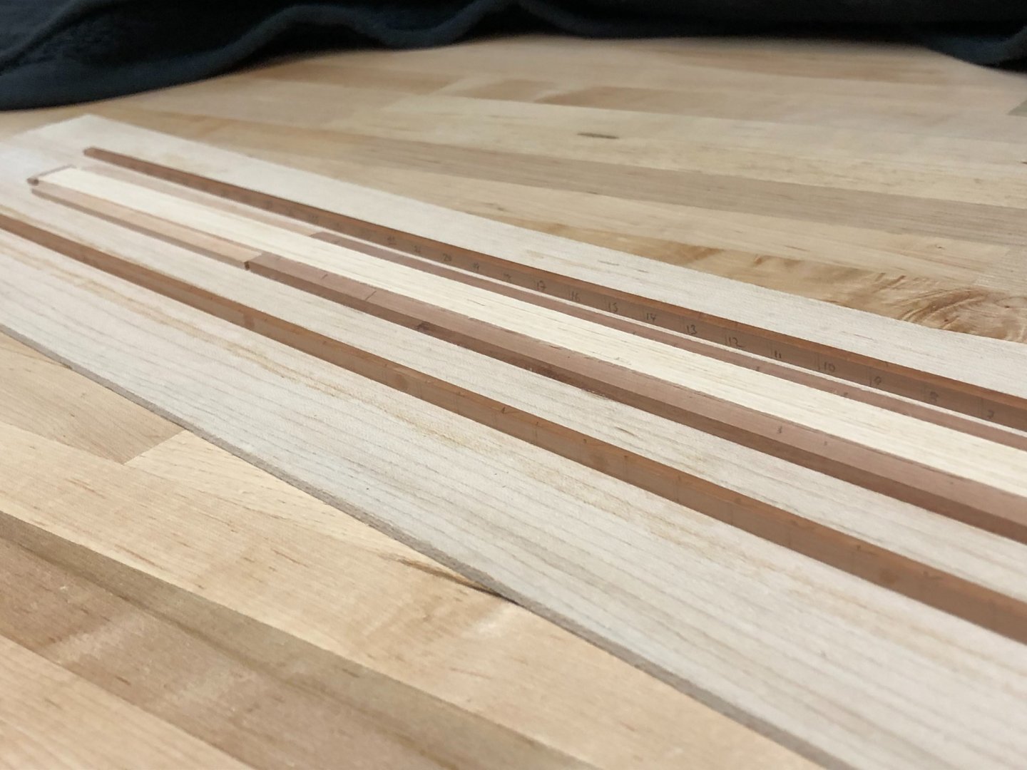
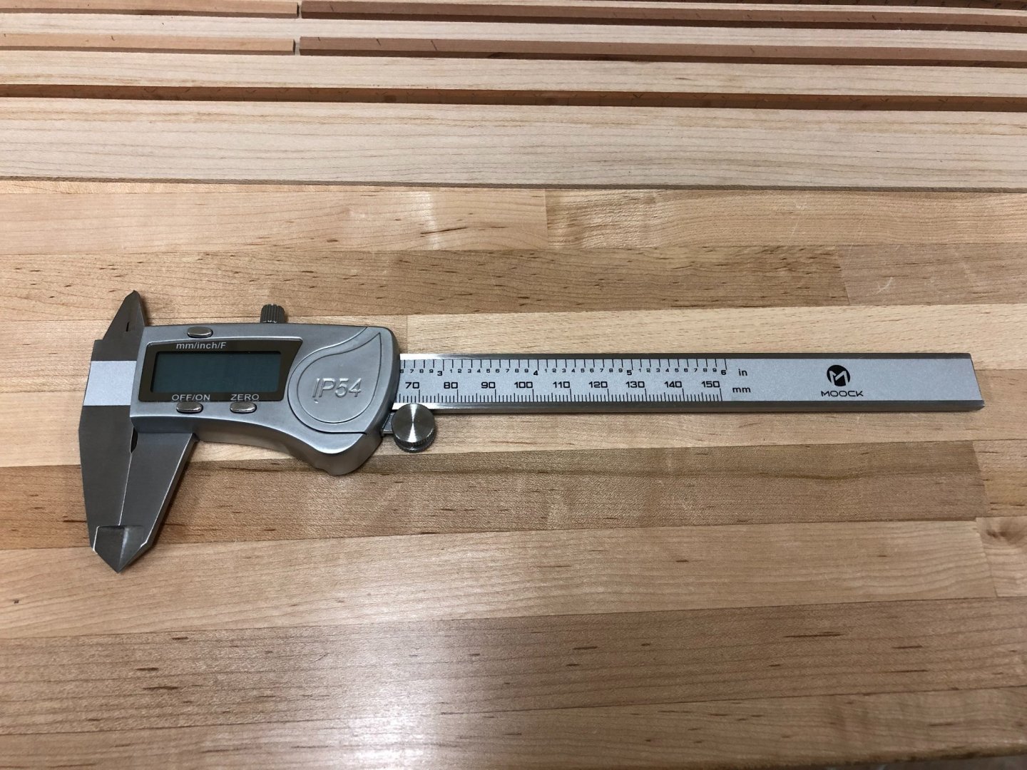
Thanks everyone for not forgetting me! @BE - Yes, I will glaze the lights. One of my other vacillations is what with, especially as the stern lights still need to be installed. There is the kit supplied perspex, crystal clear, and I also have some thin mica sheets which are less than perfect but maybe a little bit more 'period'. Still pondering that one, luckily don't need to decide now. @Eammon - need to see you getting back into things now the Ballier is complete! @Mike - very much enjoying watching your Snake come together Planning for quarterdeck planking: Planking the forecastle and quarterdeck has had me in a state of indecision for quite some time. Of course one option would be to simply plank with standard 4mm strip. While there is next to no chance of a mess-up, I knew that I would be forever kicking myself as this would not be consistent with contemporary practice. At this time, it seems that deck planking was still done by hand and involved planks being tapered, but without being joggled into the waterway. I'm going to follow the suggested pattern in the AOTS Diana book which show a consistent taper over the full length (with consistent run fore to aft), rather than the other contemporary practice of having a wider section at the rear of some planks to allow the adjacent plank to butt into it. This approach will definitely be a big challenge, but I'm hoping that taking this slowly will at least give a chance of success. Firstly, the quarterdeck was marked out with 1cm station markers, the centerline defined and an estimate for the waterway placement. I'm planning on the waterway being about 5mm wide, so the edge was marked 6mm from the interior bulwark face to allow for an additional layer of planking. For ease, this exercise was then then repeated on a paper template, and seperate templates were created for both starboard and port sides. The width of the deck was then measured at each 1cm station. To aid this exercise, I used a newly acquired digital caliper which I HIGHLY recommend to anyone, I don't know how I got by with without one to this point - no more eyeballing to the nearest 0.5mm! To minimize error, each measurement was taken 3 times and then averaged on each side. This highlighted something that is not too surprising, that is that the the hull is not symmetrical, and varies in width from the centerline by up to 1mm, and needs to be accounted for. All of these measurements were entered into a spreadsheet to estimate the required taper for each plank, and which allowed certain constraints to be resolved (for example, a whole number of planks are needed (!), and that the width of the plank at the aftmost end shouldn't be less than 50% of the widest part of the plank.). The small discrepancies between the starboard and port side were resolved by simply averaging the two, mainly to avoid the need for different tapering approaches, and hopefully these discrepancies can be resolved without being apparent to a typical observer. The spreadsheet allowed the overall planking plan to be determined at each station, so that this can continually be checked as planking progresses. To give everyone a sense for where this landed, the desired plank is 3.85mm at its widest, tapering to 2.16mm at its narrowest over a length of 35cm. Now the plank widths were known, 2 templates could be made out of some spare pear stock. (These were fine tuned after temporarily glueing together) I was very happy with how this turned out, and it proved possible to get to a high level of accuracy with time and care. These templates were then glued onto a board, and jig to hold planks placed in between. Each plank was rough shaped to remove 75% of the needed material, but then finished with ever finer sandpaper. The sandpaper was placed in the center of a block that slides on the templates to provide the final shape. Electrical tape was placed on the templates to help protect them, and also offset the thickness of the sandpaper. The bottom photo shows the first 10 planks having been finished. I was very pleased with the level of accuracy that this gave, there being very little difference between the planned and actual. Next step will be to start getting some of these installed, and continue shaping the remainder that will be needed.
-
Congrats on reaching this milestone, looking very nice Mike, especially mounted on her stand.
-
Hi Vane, nice update and good to see the planking progressing so well.
-
Flag lockers are a great addition Mort, all looking very nice indeed.
- 60 replies
-
- 1
-

-
- victory
- caldercraft
- (and 1 more)
-
Looking good Stergios! Getting close now to the finish line.
- 1,144 replies
-
- 1
-
-
- snake
- caldercraft
- (and 1 more)
-
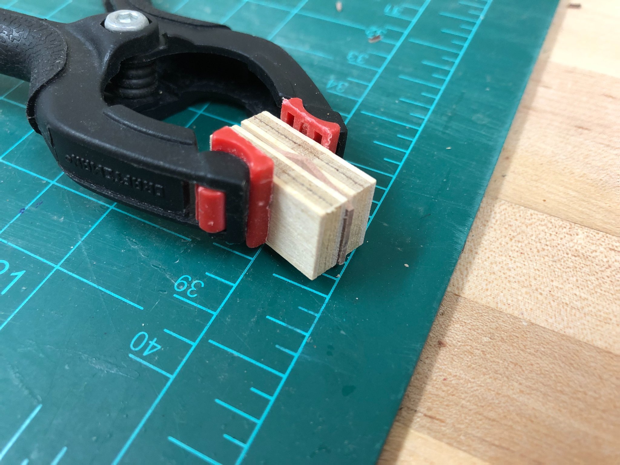
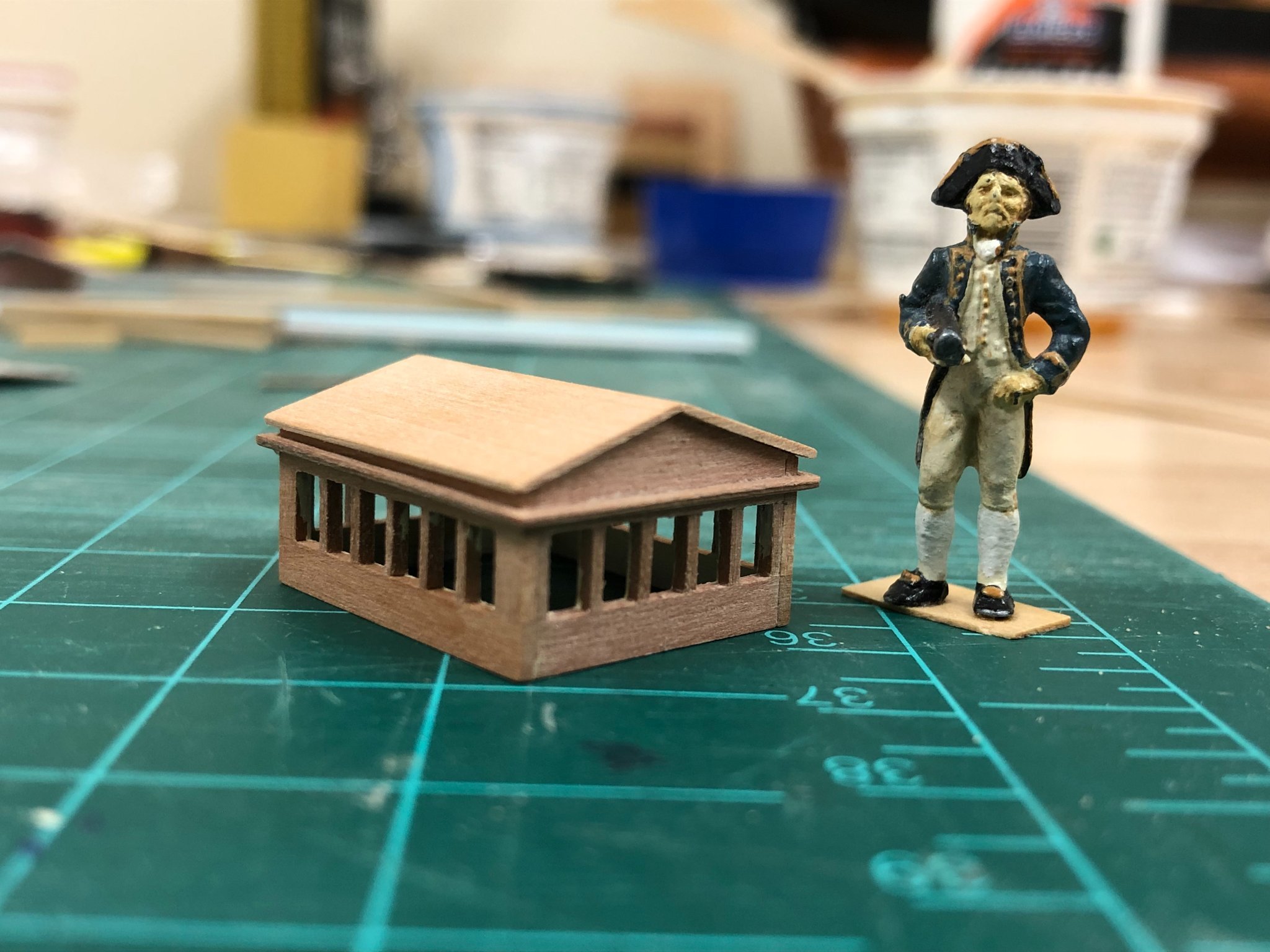
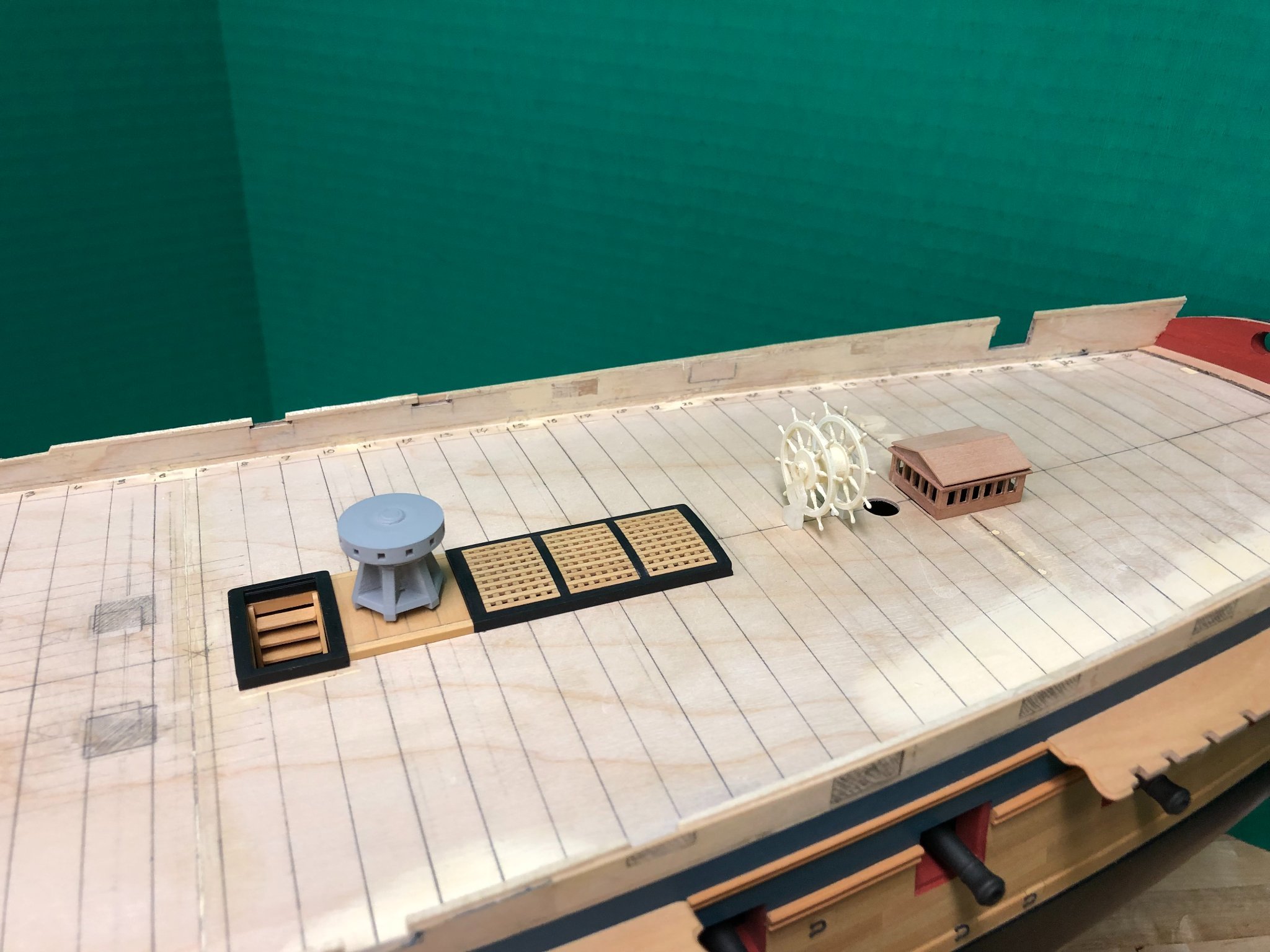
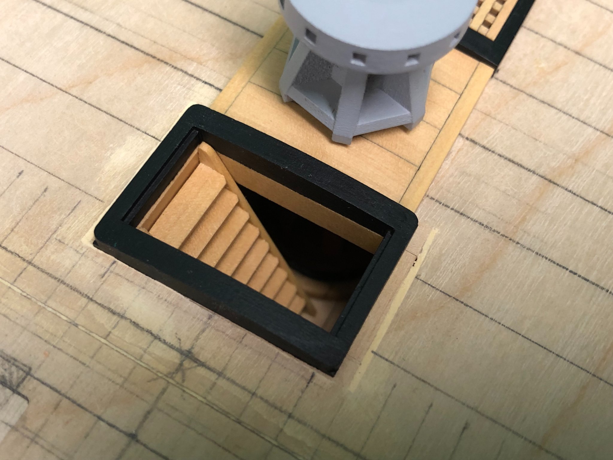
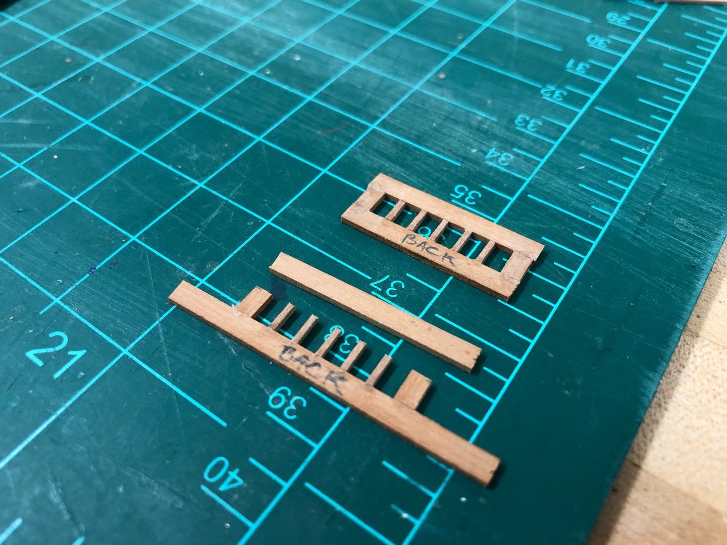
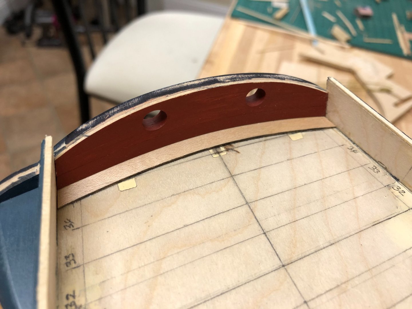
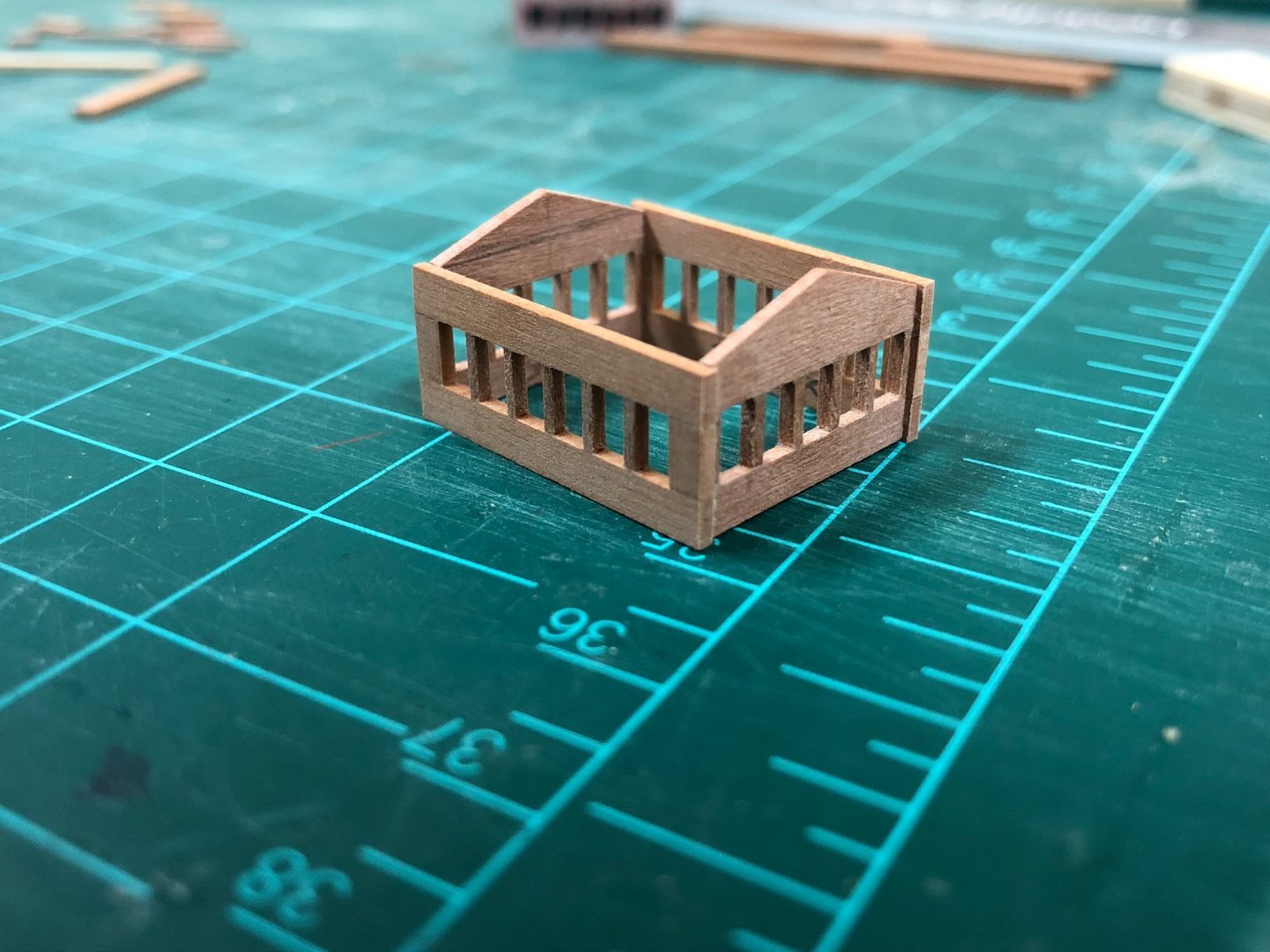
Time to clear away the cobwebs and dust from this buildlog and play a little catch-up. Have been grabbing a few moments here and there to on some items that aren't really that interesting, and especially mulling over the approach to take on a few things. The quarterdeck and forecastle decks are in place, this is a very large piece so these were cut into more manageable sections which works better for me, otherwise I find that the PVA glue has set too much by the time all surfaces have been glued up. Cutting sections at points where there is support from the beam underneath makes this a much more manageable exercise and allows the sheer of the deck to be maintained. Once installed, glue was forced into the gap at the edges of the deck to prevent any future flexing, and then filled and faired to get as smooth a run as possible. The stern fascia has also been finished with some interior planking and a preliminary coat of paint, a margin deck plank installed and the rear gun ports finished. The strips on the stern fascia were shaped by steaming longitudinally first, otherwise the two compound curves would make this very challenging. One feature that I've been obsessing over is the quarterdeck skylight. The kit provides a structure that reminds me a lot of a small greenhouse enclosure, and this is a feature that I found hard to find many suitable examples of on contemporary frigate models. The various Artois models show both an exaggerated grating or the 'greenhouse'. Somehow I mislaid some of the pieces so scratching something myself was always going to be a requirement. Like many features, this seems to be a transitionary period, moving from the skylight being an addition to a existing companionway (e.g. clerestory style top that is wider than long - the example BE put on his Pegasus being excellent example), to more modern structures that are longer than wide and form the more typical shape. Interestingly, some slightly later plans (e.g. the very slightly later Leda class) show this feature on the plans suggesting it being a more permanent or standardized feature, but none of the Artois plans show anything beyond a small coaming. In the end, I decided to take some inspiration from HMS Trincomalee, and build a structure that has side lights similar to the cleristory top, but with solid wood roof. In the main, the was driven by the fact that glass at this time period was still realistically only available in smaller panes, and that a solid top just seems a little more utilitarian and cost effective. Once that decision was made, I needed to figure out how to execute... Firstly, a very simple jig was made up with blocks the size of the needed glass panes, this would allow the narrow strip to be secured while being glued to what will be the lower part of the structure. The method of assembly required that at each end, a wider 2mm piece is needed to simulate what will be the corner structure. Once dried, the supports can be cut back to th e necessary height before removing from the jig. The upper structure can then be attached out of the jig either a strip for the side wall or a shaped 'end'. The end of the left and rigt supports are approx 1mm wide so that when joined with the sides the corner support will be of consistent dimension. When fully glued, the structure is stronger than I expected, but still clearly very delicate. The end pieces were cut back as close as possible flush to the last support with a knife, but the last effort had to be with a sanding stick. Clamping the structure between some ply offcuts allowed the ends to be carefully sanded relatively safely. The structure could then be assembled, lego blocks were used to keep everything as square as possible. Once fully cured, a rectangular section was inserted to introduce some additional strength (forgot to take a photo) before the side were carefully sanded back flush. A profile was introduced into some 1x1mm strip for the upper molding which was attached prior to installing the sloping roof pieces. Not finished yet, but this is sufficient to allow for some planning of the deck planking. And finally, the various coamings and capstan partners have been made up to give a sense for the layout. These items will be attached to the subdeck so deck planking will butt up against them as was actual practice which I suspect will prove to be a little challenging, but more to come on that hopefully. One compromise that I saw as being unavoidable is that the 3 hatchways directly aft of the capstan should taper slightly. In practice I believe that the battens in the gratings themselves would taper as well, but that is just not an option. Given that it would look very odd to my eye to taper the coamings but not the gratings, the decision was made to not taper. Don't think this will be noticeable, and a compromise I can happily accept.


-
Loving the progress and especially the figures. I'd definitely be tempted to continue working with the Royal Watermen, a full compliment would be a really striking addition to enhance the model. Think if you can get a little more 'flounce' to the bottom of the jacket to differentiate from the breeches they'll look great.
- 185 replies
-
- 2
-
-
- queen anne barge
- Syren Ship Model Company
- (and 1 more)
-
Very interested in following along, this subject and kit doesn't seem to pop up too often.
-
Wish you all the best in your endeavor's Chris, I think you are truly re-invigorating the PoB kit market with some outstanding high quality kits, and also providing a source for quality scale mini-kits for many fittings that seem to have been missing in the market place.
-
Looks like a fascinating project and a fantastic kit! You seem to have a very good idea on how to approach this and its welcome that you looking for a solution that considers different skill levels.
-
Looking at the picture of the barrel and the carriage, think your problem simply comes down to the supplied parts. The carriage looks a little big for the cannons provided which may be contributing to the problem you're seeing. The common consensus seems to be that the metal Amati carriages are not the most authentic. If you're set on keeping these items, my suggestion would be to add some additional wood quoins (on top of the simulated molded one) to raise the level of the rear of the barrel.
-
I hope you enjoyed a "Dunnock's" Tea Cake while you were there (boom boom!..sorry couldn't resist). Yes, sadly Unicorn has seen better days, and rapidly approaching the point where her situation needs to change, either major work or dry docking, if she isn't to deteriorate beyond redemption (she's hogging badly). Despite her less than impressive condition, she is far more 'original' than her sister Trincomalee and an fascinating way to see the evolution of building techniques from the same design. I find it amazing that there isn't an AOTS Book on the Leda class, given the surviving evidence and likely modeling interest considering the historical significance. I think Chris Watton was/is contemplating a future kit design of this class, so hoping that does come to fruition. BTW - The roof which was installed shortly after her completion is also original, and is the only surviving example from when a ship was placed in ordinary - and so is somewhat almost as historically significant as the ship herself.
-
I don't believe it! Well done indeed sir, you've done her proud and she's looking mighty fine. Really fine model Eamonn.
- 1,039 replies
-
- 1
-

-
- ballahoo
- caldercraft
- (and 2 more)
-
HMCSS Victoria 1855 by BANYAN - 1:72
Beef Wellington replied to BANYAN's topic in - Build logs for subjects built 1851 - 1900
Love the way all the details are coming together in such a detailed, authentic and harmonious way!- 1,021 replies
-
- 4
-
-
- gun dispatch vessel
- victoria
- (and 2 more)
-
Hi ECK, I always hate to make observations on other peoples work (but always hope people help identify my mistakes!) so forgive me, but the wale looks to be too wide. Hard to tell from the angles of the photo's, the top seems to sit abut right but the bottom extends lower than I would have expected which may result in the top of your coppering being too far down the hull so may be worth double checking.
-
That rope looks fantastic Ben, looking forward to you opening your store? Hard to tell in the photos, are the colours similar to Chuck's rope?
-
Great solution Rob. I think you state some very wise words, important to understand the various sheer lines that features that follow, either the sheer of the deck or the sheer of the wales.
-
Hi ECK, apologies for missing your start, although you're making amazingly fast progress. There are a number of current Diana/Artois build going on on the site right now and always good to see another. Your other builds look great, hope you don't mid me pulling up a chair to follow along.
-
Have you truly been away? I think we all have periods when other activities are the focus. Keeping my eyes peeled for a new build log 🙂
-
Nice progress David! Sure you've thought it through, I'd be tempted to simplyinstall another layer (or 2) of planking above. Given that these would terminate at the sternpost and below the waterline I suspect it would be very hard to see once sanded. I had to use a similar fix, albeit on the first planking.
-
Glad to see you have started this BE, keel section is looking very nice. I've jumped back in myself and trying to figure out where I was a year ago...
- 185 replies
-
- 1
-
-
- queen anne barge
- Syren Ship Model Company
- (and 1 more)
-
Congratulations Rob, a really fine model indeed. Well done!