Beef Wellington
-
Posts
2,249 -
Joined
-
Last visited
Content Type
Profiles
Forums
Gallery
Events
Everything posted by Beef Wellington
-
 Could be true, although that is inconsistent as well. On the right side the 1 is followed by another numeral and is not scripted. Although hard to read, it also appears that there is no use of the medial/long s anywhere (e.g. in Bowsprit) which also seems a little odd.
 -
Glad to see you have taken these on, can fully appreciate the fiddle factor but you seem quite the old hand on these smaller boats. I agree there has been a huge gap in the market for these high quality minikits, these seem like a great upgrade to the older kit supplied options.
- 70 replies
-
- 2
-

-
- 22ft Yawl
- Vanguard Models
- (and 2 more)
-
Looks great Rob! You've clearly been busy. Forgive me if I missed it, what did you decide on for the topgallant masts (stump, common or long)? Also curious if you are following the plans, or the rigging diagram in the AOTS Diana book, and whether you've seen any differences.
-
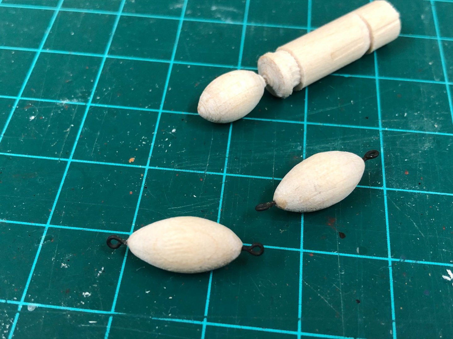
Michael - welcome aboard and thanks to you and the others for the interest. Nun-Buoys: I've been trying to get my head around these for some time, there seems to be little info on these in sources but seeing how others have tackled these (esp. BE and Chuck) were of great help. I seem to recall that the buoys should be around 1/3 to 1/4 the length of the anchor but for the life of me can't find the reference or place that I read that to confirm. The body of the buoy was shaped from some spare dowel, and 2 ringbolts inserted at the extremities leaving some of the length exposed. These would have been made from leather and would have been 'served' with leather strips as suggested by Lavery, but this was a detail I ommitted, and these were simply painted with brown and black paint. In a slightly larger size, these would be fun items to add a little more detail on (as I think BE did on his on his Pegasus build) To make up the anchor buoy slings, eyes were seized into some rope, and threaded onto the rope that will become the hoops. I wasn't quite sure what size to use, but considering that in practice these would have been wormed, parcelled and served - presumably for protection - it seems likely that they would be reasonably substantial. I used some Syren line to get a little definition, and used a black marker to darken as I only had some tan stuff handy. Mounting the slings on the buoy itself proved quite the challenge. Firstly, the hoops were made up with a single overhand knot, secured with GS Hypo glue, and then trimmed. The slings on each end need to go underneath the hoop on the opposite end. I found the best method was to suspend in some helping hands to fine tune, although this proved very fiddly. Once everything was satisfactorily in position, the 4 slings were seized around the ringbolt (which simulates the loop the slings would make), and then trimmed. This was then attached to a pre-made coil to represent the length of rope needed for given depths of water, and then secured to the shrouds for storage, and attached to the anchor. On many models, these are shown as rather drab items, I have to believe in practice that these would have received some sort of brightly coloured paint to aid visibility, but I stayed with the more conservative muted tones. So at this point, the only item remaining to be completed is an ensign of some sort, and some tweaking of the rigging...


- 800 replies
-
- 14
-
-
- snake
- caldercraft
- (and 1 more)
-
definition of "prolific" - producing a great number or amount of something, an abundance of inventiveness or productivity I think your comment "I have no room anymore" proves it 🙂
- 164 replies
-
- 1
-

-
- vanguard models
- flirt
- (and 1 more)
-
Just incredible what you are achieving Mike, hats off to you dealing with that insane PE at that scale, looks great though. How do you fold the PE at this scale?
- 179 replies
-
- 9
-
-
- hatsuzakura
- pit road
- (and 2 more)
-
Hi Dunnock, great to see another 'Diana' coming to life, looks like you are thinking well ahead. I'm sure you've seen many of the other fine builds going on right now and I'd suggest letting folks know you've started your log. Sure you'll get plenty of support and this kit definitely has its head scratching moments. Look forward to more.
- 310 replies
-
- 2
-
-
- Diana
- Caldercraft
- (and 1 more)
-
Good decision, if its any consolation, one learns more from correcting and redoing mistakes than doing it right the first time...at least in my experience.
-
Welcome to the Snake club Matthew, you seem to have made a very solid start. Definitely don't be afraid to fair the bulkheads a bit more, that will really help you get a smooth line of the planking.
-
Looks pucker from where I'm sitting Peter, well done. Are you going to rig the catharpins?
-
VTHokkiEE has given some great advice. Looking a the planking tutorial will really help explain how to approach it, the balsa strips look quite thick compared to other kit supplied wood, and will make following the basics more important. Planks do not naturally want to curve in 2 dimensions at once and will likely try to twist out of the intended hull shape if forced as you seem to be experiencing. Look forward to seeing how you tackle it.
-
I'd definitely recommend starting a build log. Although it would possible to add some shims to fill the gap, I think you'd run the risk of altering the shape of the hull away from its intended form as the gaps look quite significant. I wonder if you faired the bulkheads sufficiently? More photos might help with better advice.
-
Chris - I'm assuming that even though Amati have not released this, they still own the rights to your design so you could not release under Vanguard?
-
Hi Mike, think this picture from earlier in log explains it best (Post #323 on page 11). Definitely a good idea to do this before installing the cat heads on the model as I think you'll get better results. HMS Snake by Beef Wellington - Caldercraft - Scale 1: 64 - First wooden ship build - Page 11 - - Kit build logs for subjects built from 1751 - 1800 - Model Ship World™
- 800 replies
-
- 2
-
-
- snake
- caldercraft
- (and 1 more)
-
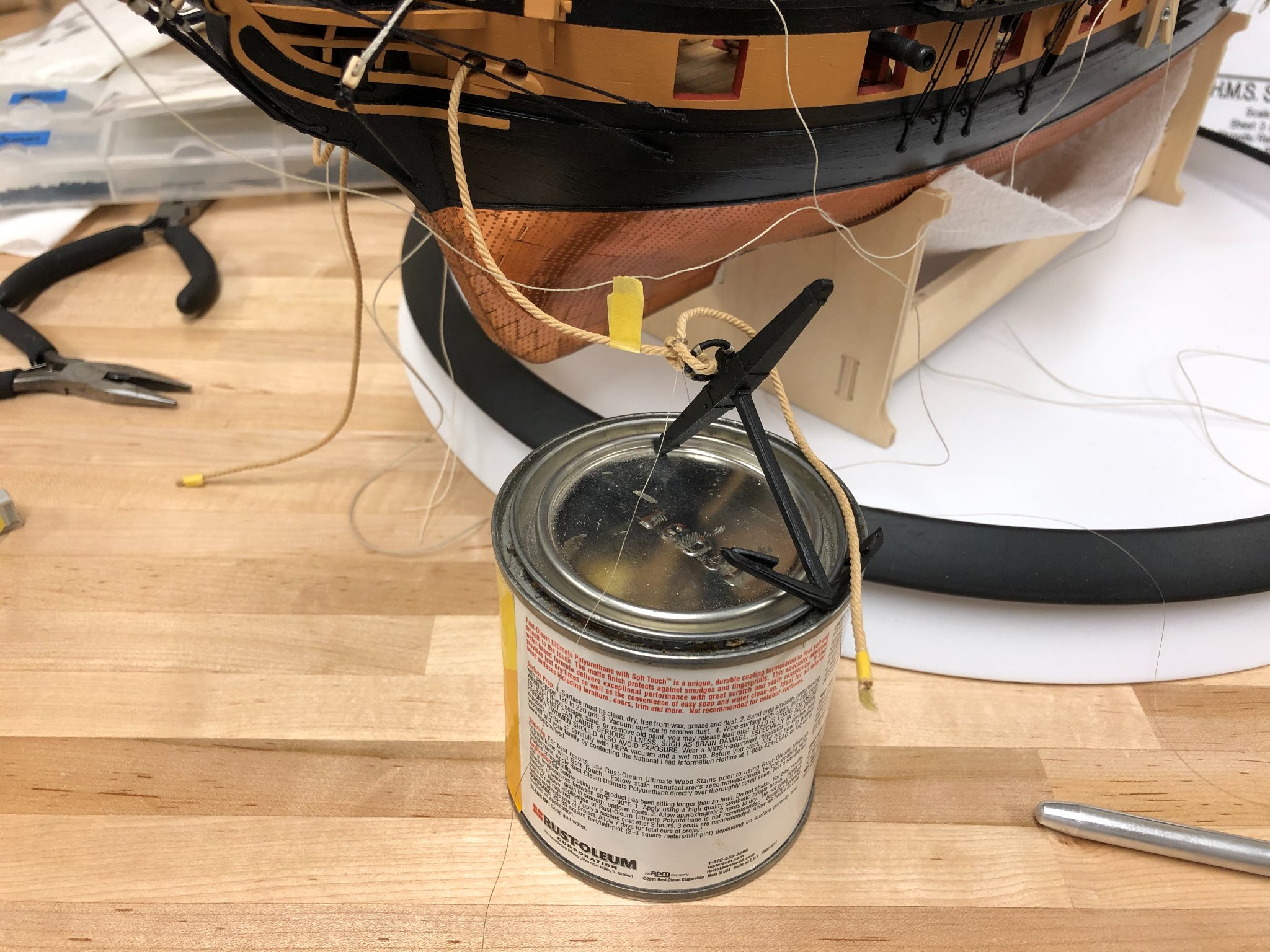
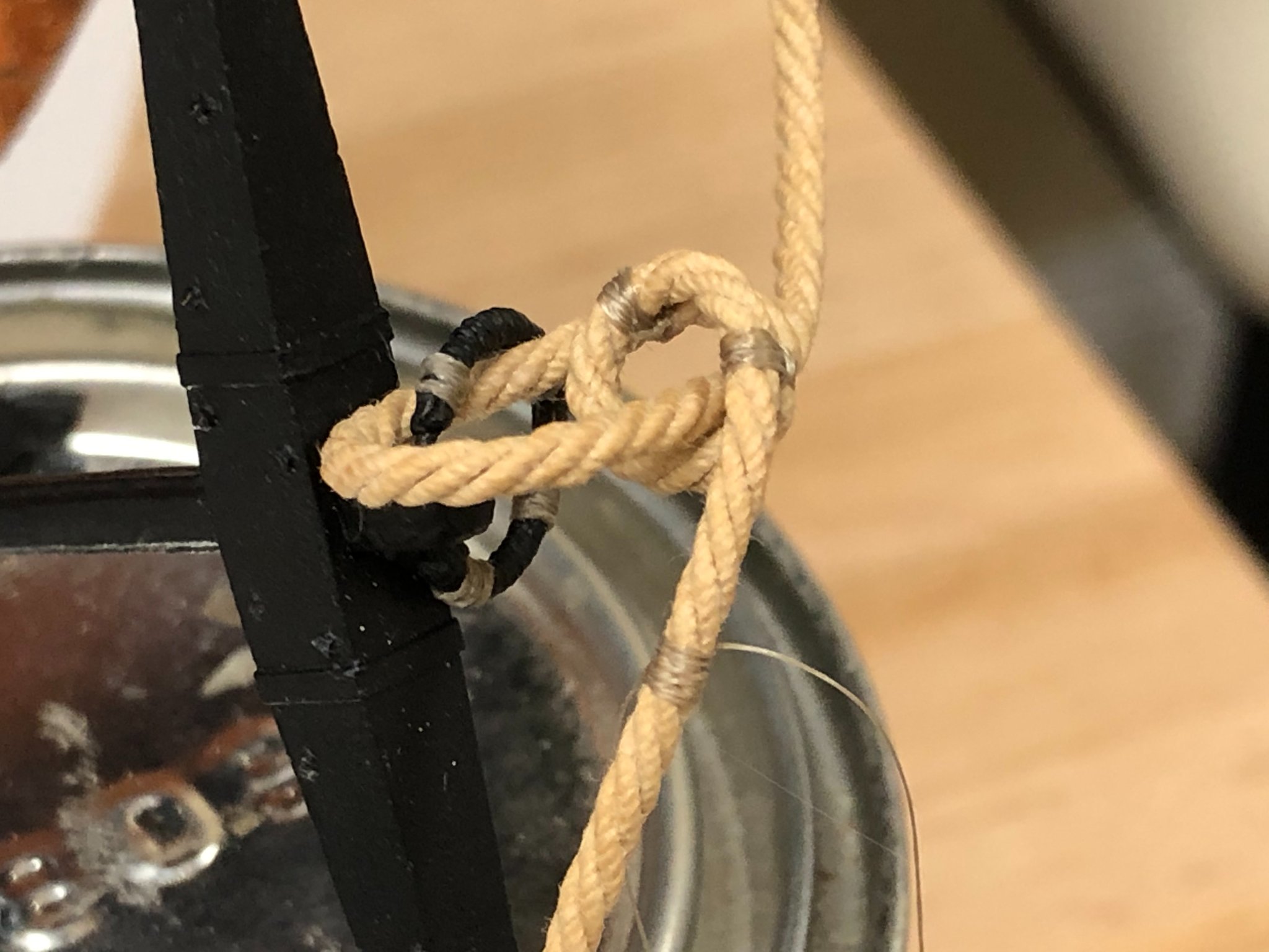
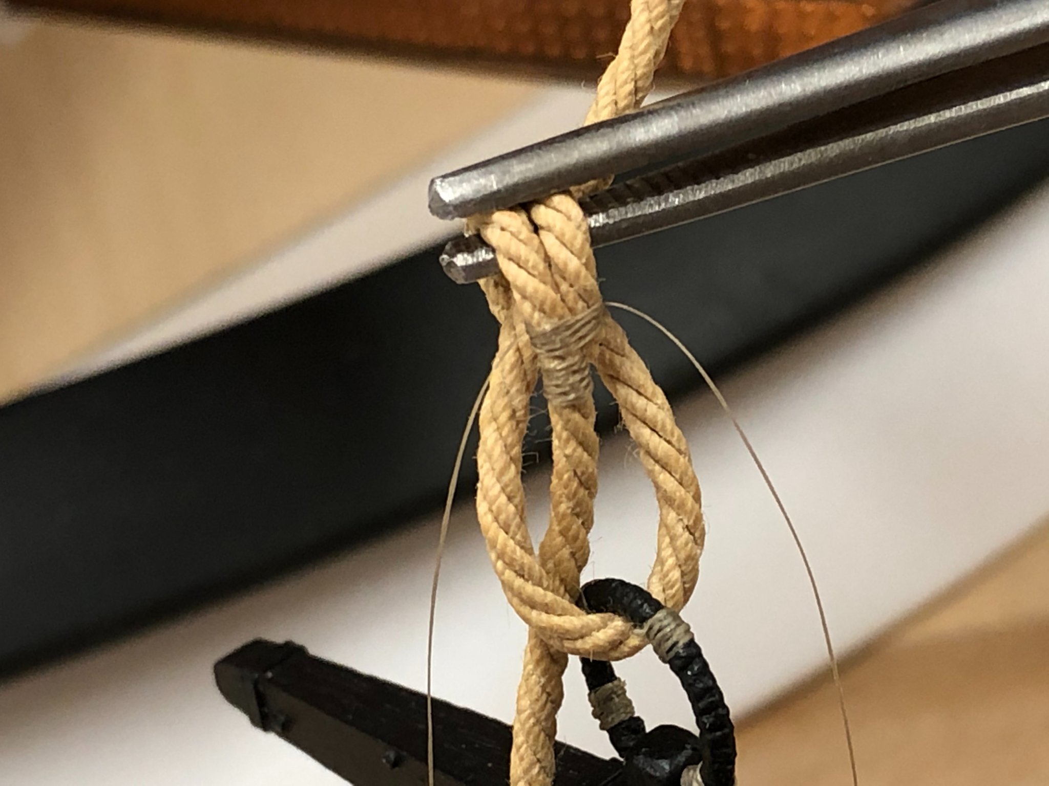
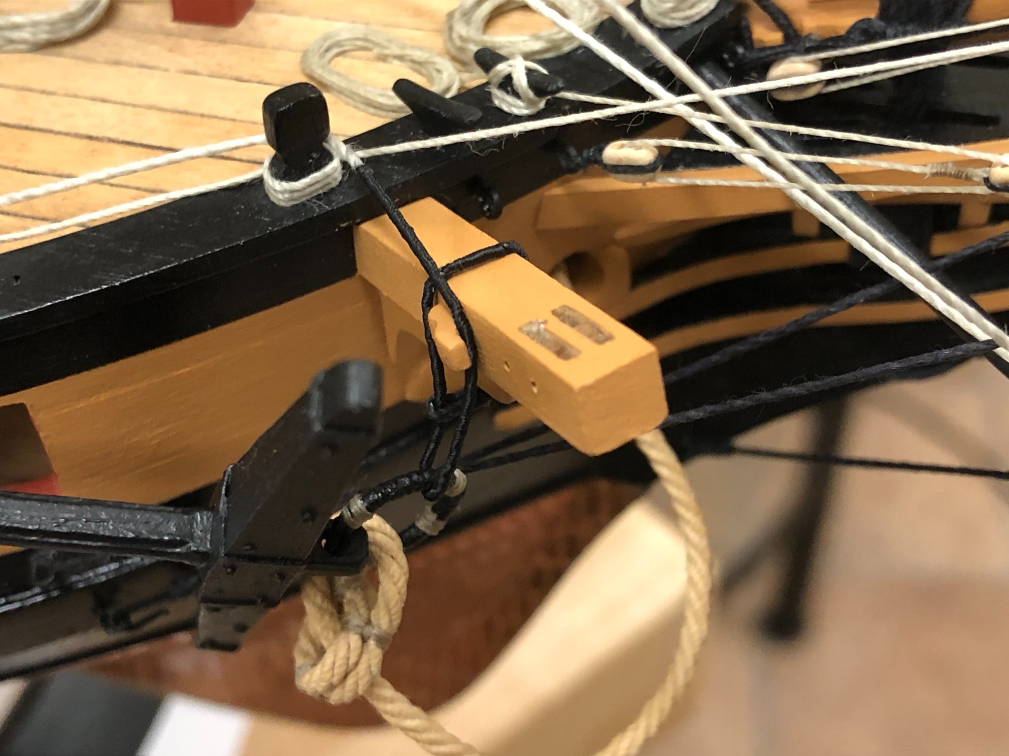
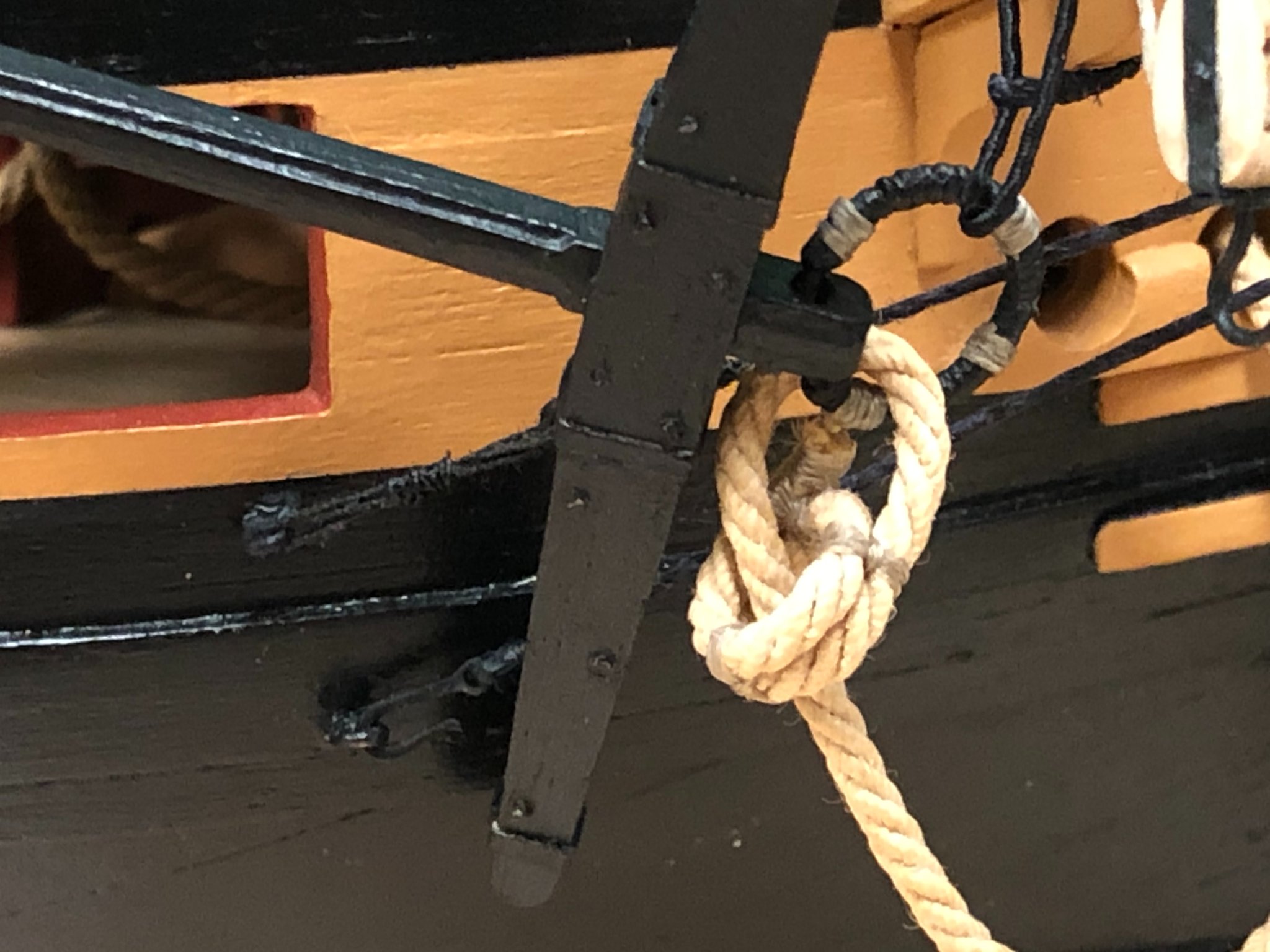
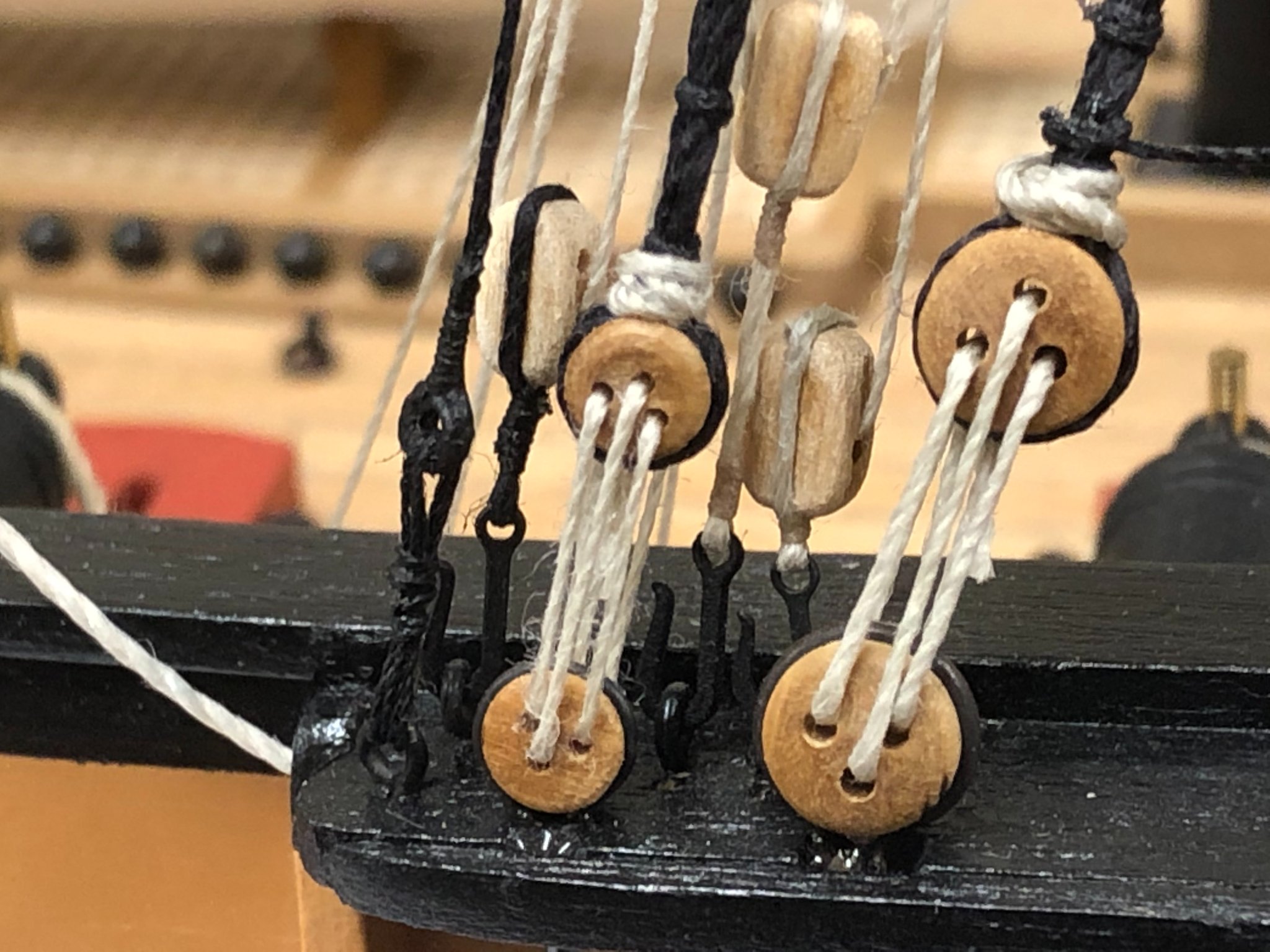
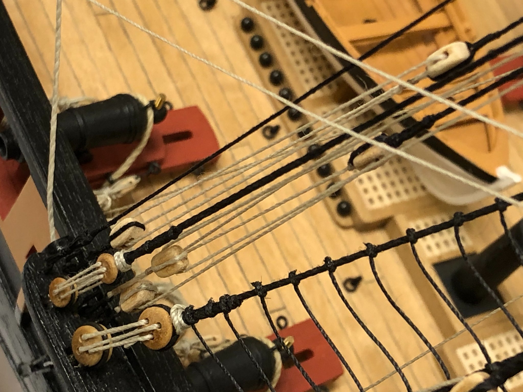
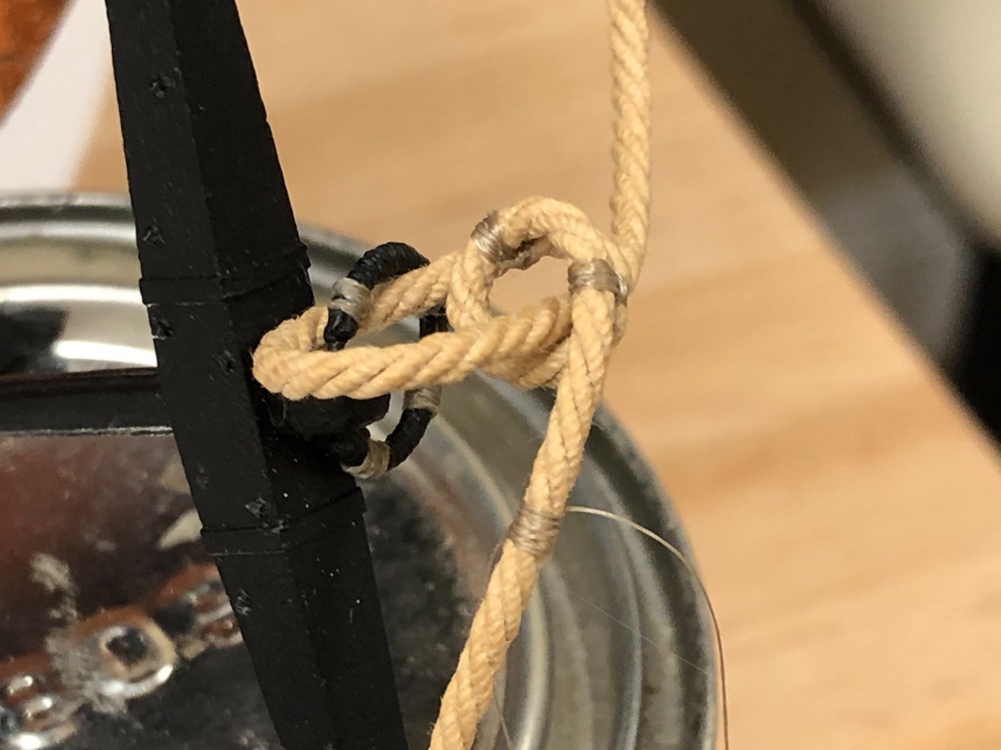
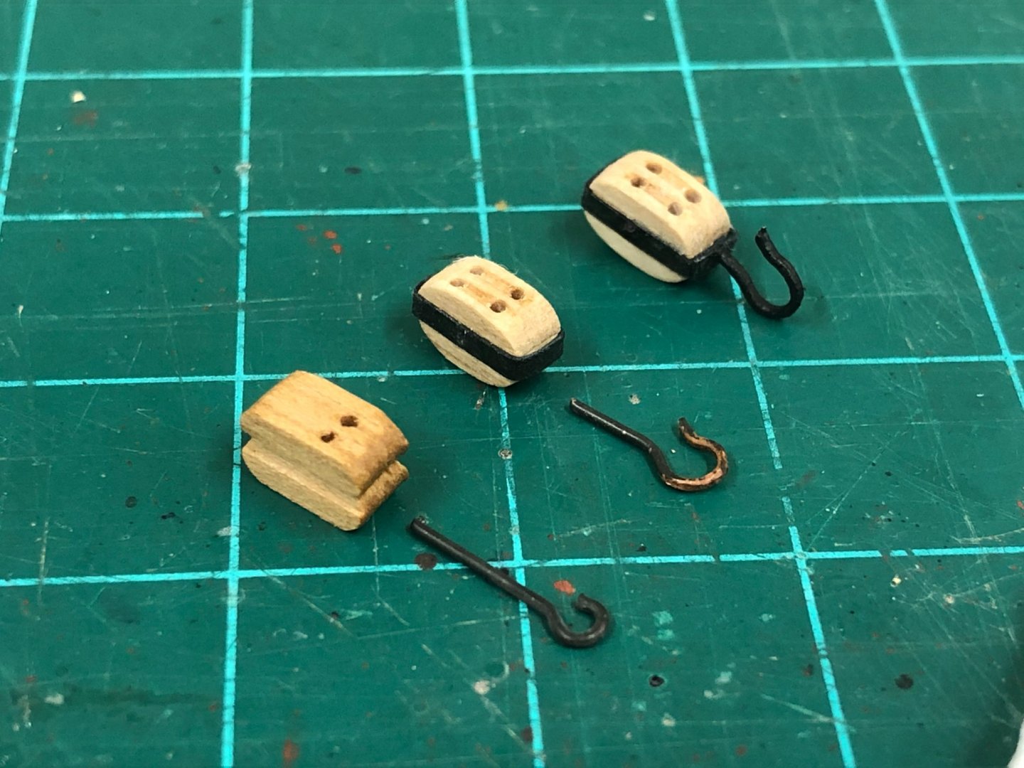
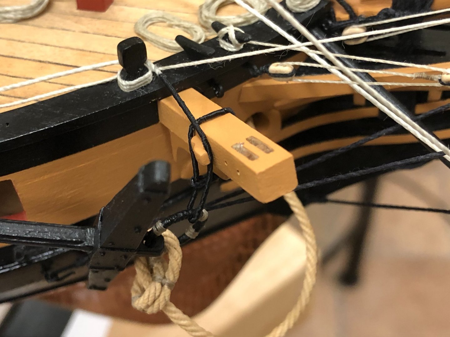
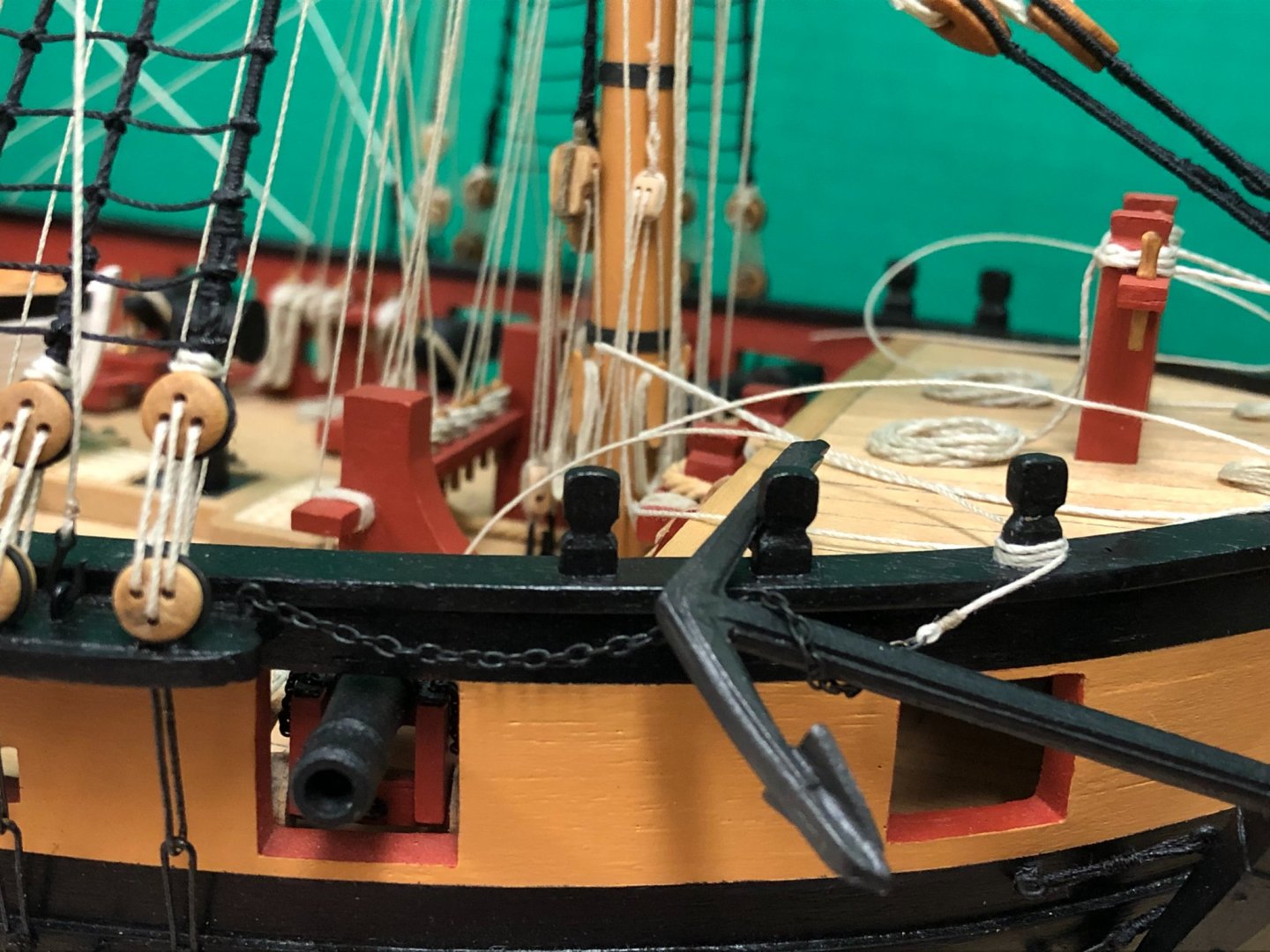
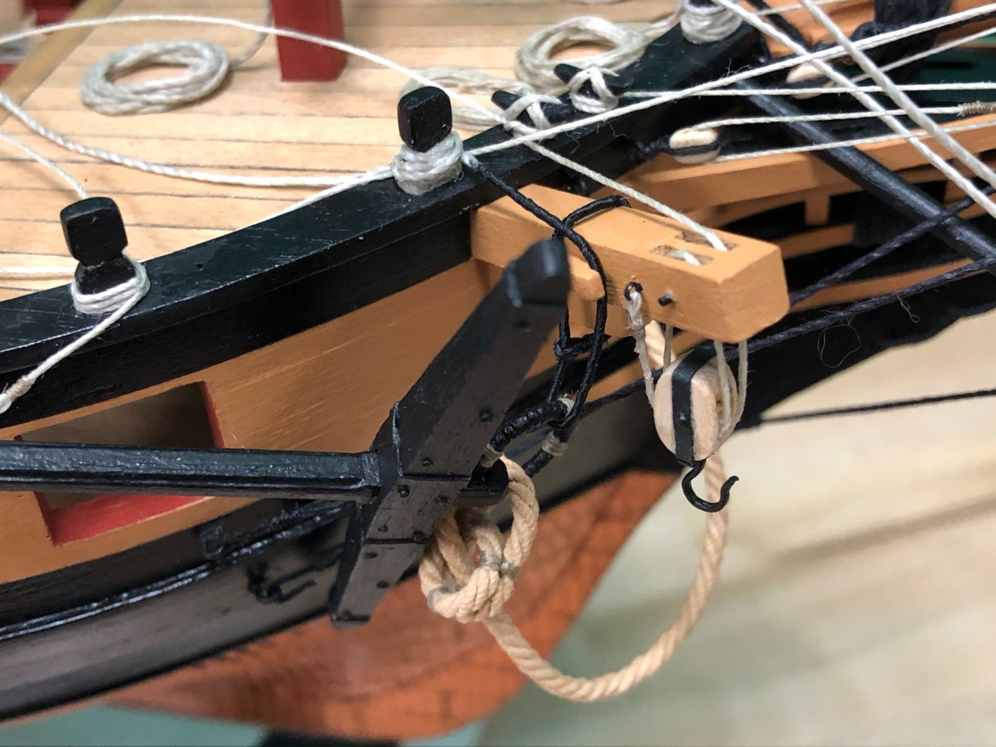
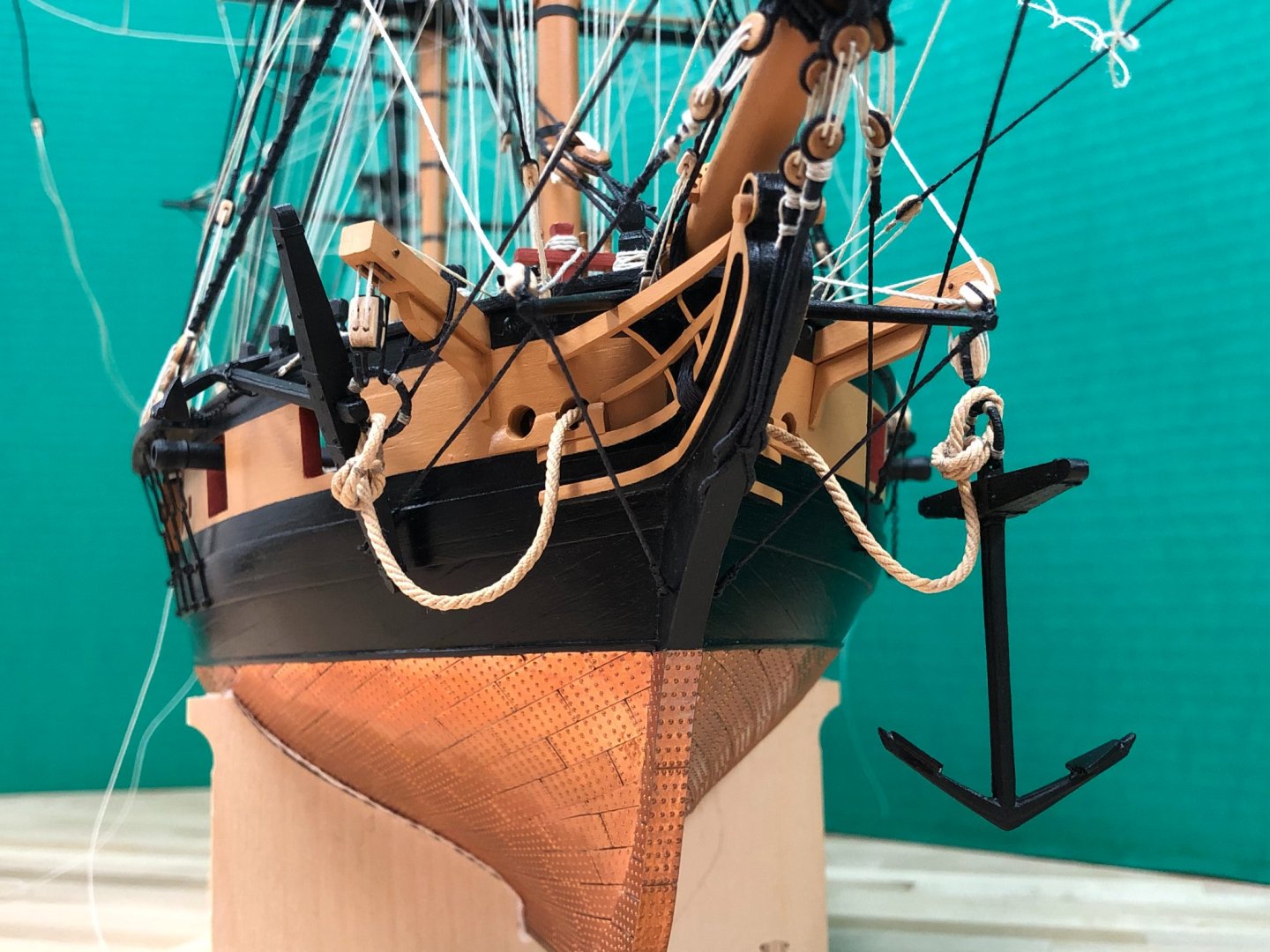
Thanks whitejames, Eamonn, Joe, Martin, Stergios, mugje, Mike and all the 'likes' for the continued interest and encouragement. Happy New year to everyone! Anchors: Adding some appropriate features here at the bow will do much to enhance the overall look of the model, the kit itself leaves the bow area a little sparse, especially the rigging which has already been commented on. The kit provides 4 full sized 'bower' anchors. However, Steele indicates that a ship of Snakes size and class would only carry 3, in addition to a smaller kedge and stream anchor : “Ships of 110 to, 100, 98, and 90 guns, have seven anchors; from 80 to 20 guns inclusive, 6 anchors; ships of 300 tons, and sloops, have 5; and brigs and cutters 3 anchors.” - This would include the large (best, small, and spare) bower anchors, stream and kedge anchors. As for positioning, per Steele: "The spare anchor is stowed on the starboard side, and is seldom used, but when one of the others is lost......The stream anchor is stowed on the spare anchor; and, when used, it is sent in the long-boat or launch, with its cable bent, and let go at any particular spot, either for steadying the ship, when riding by only one bower, or to assist a ship when in shore, or to warp her, &c. ......the kedge is stowed on the stream and spare anchors, and is frequently used to stop a ship for a tide in little winds…” A number of years ago (!) I had purchased a smaller Caldercraft anchor for the kedge anchor, and luckily was able to find it. Not much to cover in the making up of these anchors, which had previously started some time ago. The ends of the stocks were rounded of and tapered. One mistake I did make that I am now aware of is that there should be gap between the two halves, speculating to retard rot. I found the 'puddening' particular challenging to complete as the pieces are hard to hold securely but finally got there - once again the 'springiness' of the kit supplied rope seems very capable of undoing work at the most inconvenient moment. The next question was how to install on the model. Info on anchor handling practices seems to be a little sparse, with diagrams and descriptions appearing in 'Lever' being replicated in other reference books. Other logs, especially BE's fantastic Pegasus build, helped fill in areas of confusion. Again Steele sheds a bit more light: “The best bower is then placed forward near the bows on the starboard side; the small bower near the bows on the larboard side, a little abaft their respective catheads; and are secured by their stoppers, from the catheads and shank-painters. The stopper has one end clinched round the cathead; the other end passes through the ring of the anchor, returns upwards, and leads over a large thumb cleat bolted to the cathead, and is made fast with several turns, and the end hitched round the head-rail and timber-head, on the fore side of the cathead.” Anchor hawse clinch: The approach to attaching the hawse to the anchors using a clinch is shown pretty clearly in 'Lever'. A bight is made by lashings ("no larger than the anchor ring") and the hawse fed through the anchor ring and the bight. Nothing too complicated, but this was rather tricky to execute because it needed to be done in situ, a tin was used to rest the anchor while this was performed. Before the last bight lashings were put on, the intended end of the hawse was seized to prevent it unravelling once cut. This approach seemed to work well, and the extra untrimmed length of the hawse was helpful in keeping things positioned to allow the last lashing to be put in place. Anchor stopper: Per Steele: "The stopper has one end clinched round the cathead; the other end passes through the ring of the anchor, returns upwards, and leads over a large thumb cleat bolted to the cathead, and is made fast with several turns, and the end hitched round the head-rail and timber-head, on the fore side of the cathead." The rope would likely need to be reasonably substantial, and given a diagram in Lever which corroborated, 0.75mm rope was used. Although the size looked appropriate, the poor quality of the kit rope led me to look for options, and a solution became clear after looking at some photo's of Victory. It seems the stopper was served (presumably for protection), so this was replicated and it went a long way to improving the visual appeal. Cat block: The cat blocks seem to be a nice feature to add for visual interest. The blocks were made up from a couple of kit 7mm double blocks and shaped. Card was used for the iron band and brass ringbolts used for the hook and the simulated axle. A small PE eye bolt was installed on the rear of the cathead and 0.5mm line attached and fed through the block before securing to a cleat at the base. Shank painter: Per Steele: "The shank-painter hangs the shank and fluke of the anchor to the ship's side outboard; and when stowed, the shank-painter is passed under the inner fluke round the shank of the anchor, and made fast with two or three turns, and the end stopt round timber-heads on the forecastle." Lever also has a well replicated diagram showing how this would be used. Luckily I had some spare chain left over from the rudder, and this was used for the shank painter together with some 0.5mm line. At first, I felt this was a little oversized, but looking at photos again of Victory it doesn't seem too out of line. Against the black background of the hull it sits OK with my eye. I suspect that the end of the chain ended in a hook, but this detail was omitted for convenience, as it would not be very visible. Undecided as of now whether to leave the port anchor suspended from the catblock or replicate that used on the starboard side.


- 800 replies
-
- 19
-
-
- snake
- caldercraft
- (and 1 more)
-
Beautiful boat and exquisite workmanship, and educational as always. Congratulations, Seasons Greetings and Cheers (to 2021) and a new build (and bathroom..)!
- 261 replies
-
- 3
-
-
- muirneag
- vanguard models
- (and 2 more)
-
Looking good!
-
Season's greetings Stergios! Can't say definitively whether this is definitively right or wrong, but it is at least consistent with the plans and various references I could find. It gets pretty crowded in there 🙂 Hope this helps.

- 1,144 replies
-
- 4
-
-
- snake
- caldercraft
- (and 1 more)
-
Will follow along Liam, always good to see a new Snake build.
-
Guess I got the first choice of seat, not familiar with the manufacturer or the ship so will likely be learning a lot. Looking forward to seeing some action.
-
Just found you before you got to page 4, interesting subject matter. These looked so futuristic when launched but I think they have some of the most beautiful lines - and now I find myself recognizing how quickly time flies... definitely in from here on...
-
Hi Vane, I can't quite tell from your photos the alignment of the gunports. The foremost gunport should be pierced perpendicular to the line of the hull (i.e. at an angle), all the others I believe should b eperpendicular to the centerline (the framing would dictate this). I had angled the inner face more to try and keep the hull thickness constant in section, but did not agonize over this. I don't think you should see much of a difference with the other ports. You can build in some flexibility into this simply by setting the cannons so there is a gap between the from of the carriage and the interior bulwark (as would have been seen in practice). Anyway the post below shows my tribulations in this area and mistakes made if its any help... Cheers
-
Hi Peter, just seeing your post now, hope this was an isolated incident. This seems to me to be one of the most egregious design flaws on one of the earlier Caldercraft kits, having the joint of the brass wire directly where the tension from the chains is applied does not make sense. Hope you haven't had any more failures, on my Snake build I put some spots of epoxy in the slot of the channel before attaching the shrouds to try and provide a little more structural integrity. Merry Christmas!