

James H
-
Posts
5,618 -
Joined
-
Last visited
Content Type
Profiles
Forums
Gallery
Events
Posts posted by James H
-
-
6 minutes ago, Mike_H said:
Some questions:
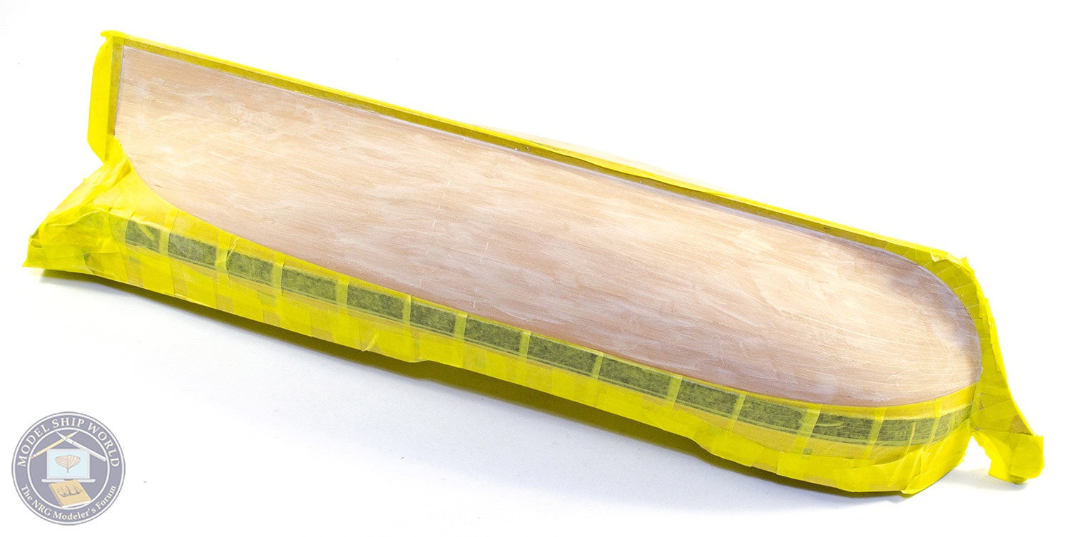
I'm sure this will be clear in the manual, but did you change your mind about masking-off the keel? The photographs shows it masked but then painted.
What kind of filler do you use? It looks fine-grained, hard, and buff coloured - all good things but I've not found those properties in one tin or jar.
Ah yes!
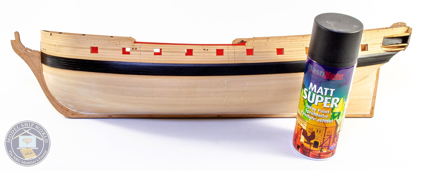
The masking tape is on the keel whilst I sanded back the filler on the hull underside. It was just to protect those surfaces. Once I was happy with the hull planks, I removed the tape from the keel and sprayed the whole underside.
I use Ronseal natural acrylic wood filler on the undersides, diluted. I also added about 50% Titebond Original to the mix as it's easy to sand, more so other Titebond glues.
- KentM, chris watton, jpalmer1970 and 4 others
-
 7
7
-
-
Morning!
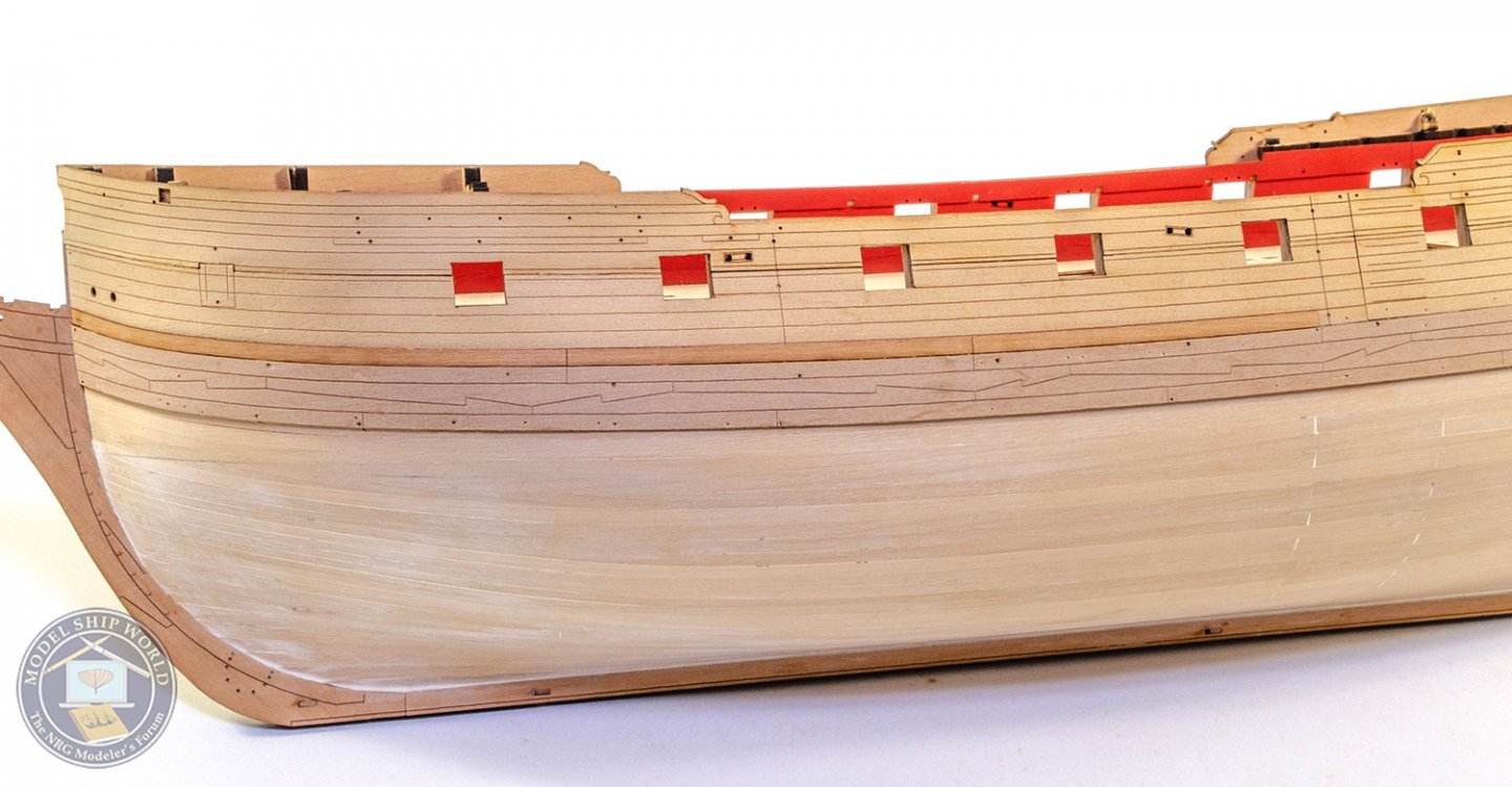
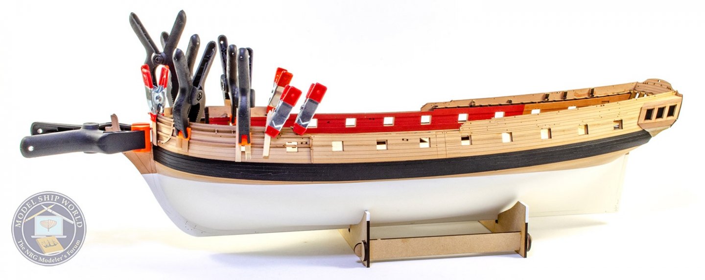
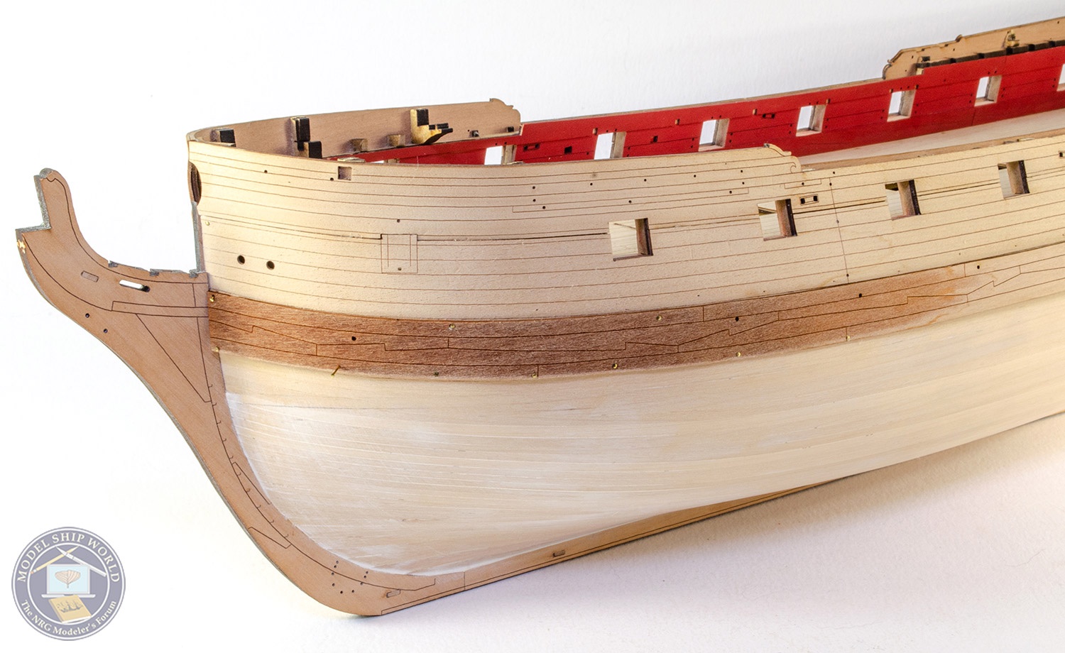
I was hoping to have more to show you, but finishing off the hull underside to get a nice even and homogenous surface really is a labour of love. Nonetheless, here's my work so far. The main wales are now fitted to the model, after a 30 minute soak in hot water for the forward half. Positioning this is very easy as it simply follows the line of the lower outside pattern parts that were fitted earlier, and covering the first two laters of later cut planks. The wales are pinned in position whilst they dry. This is left overnight as pear can expand quite a lot when soaked.

Once dry, the wales are glued with PVA and pinned in place.
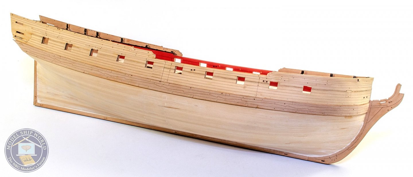
After fitting the main wales, a narrower and thinner wale is added to their upper edges. This is supplied in halves.

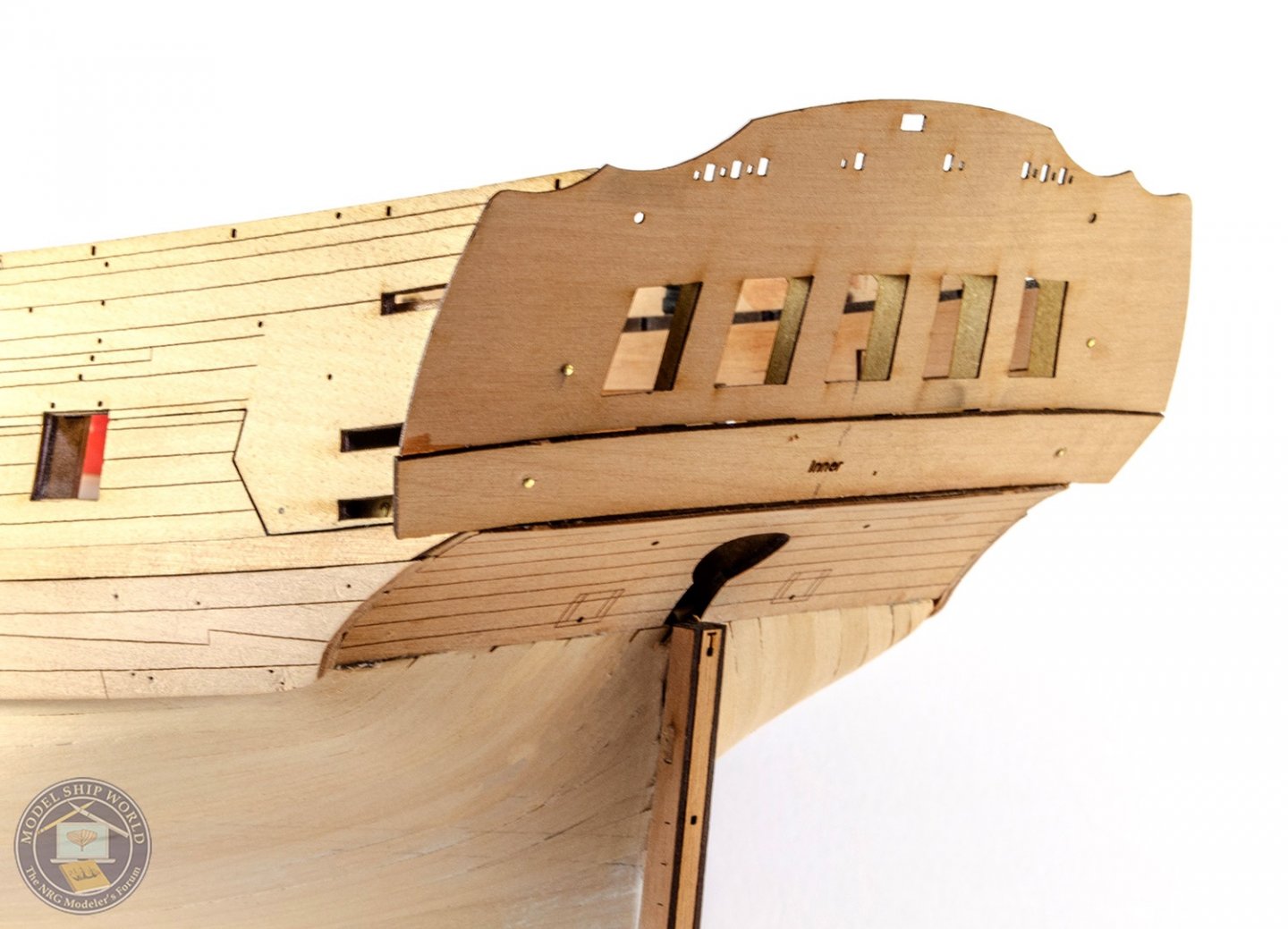
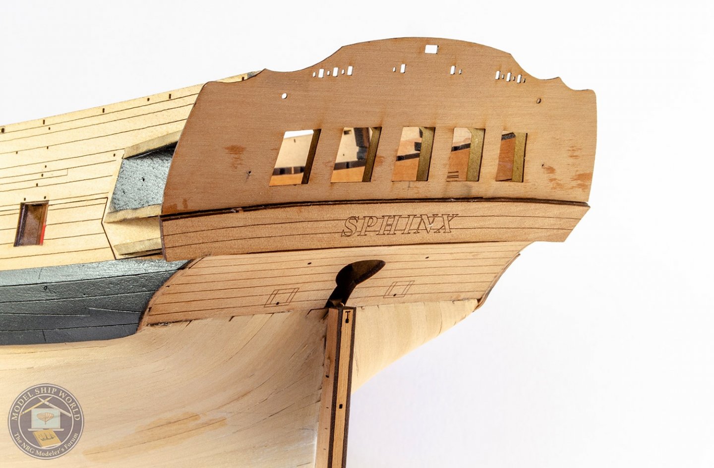
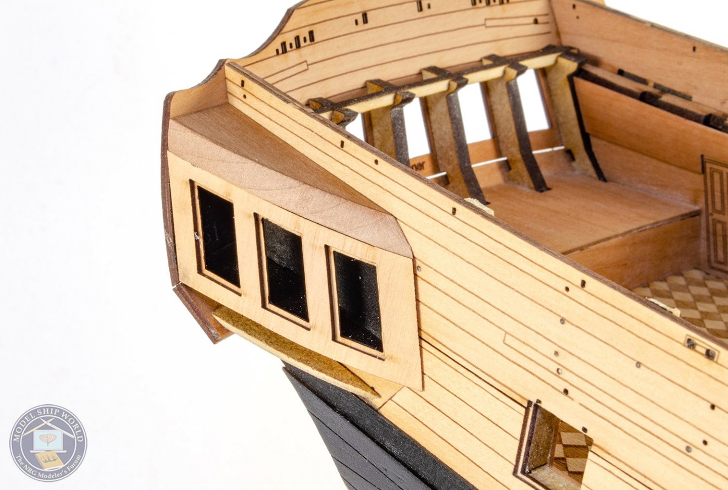
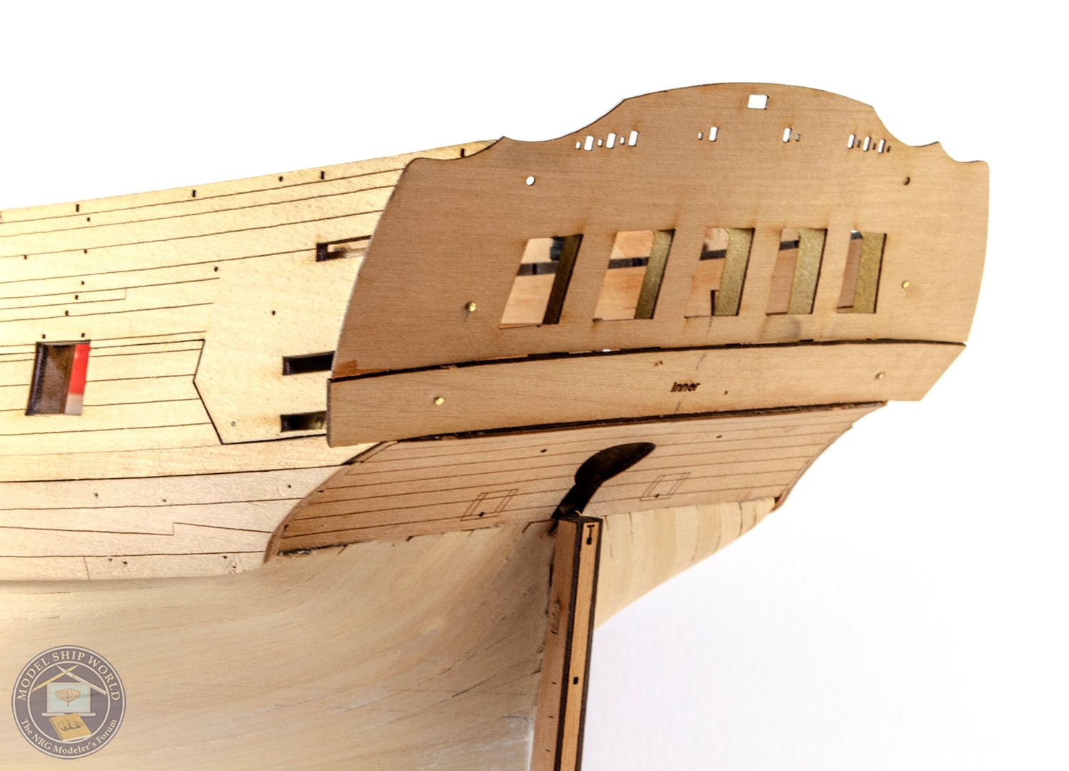
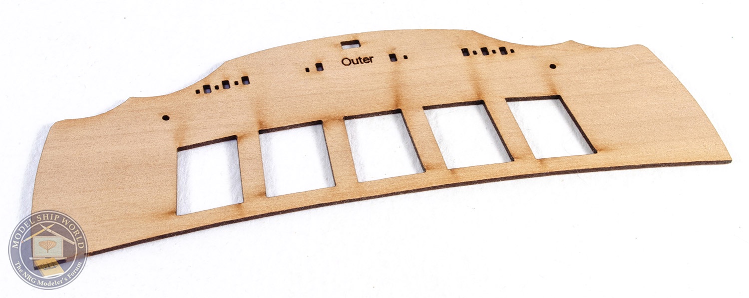
The inner stern upper counter and stern fascia are now fitted. Both these have inner and outer panels. I bevel the edges of these slightly as they butt up against each other. Some minor measurement is done to make sure the parts are central.
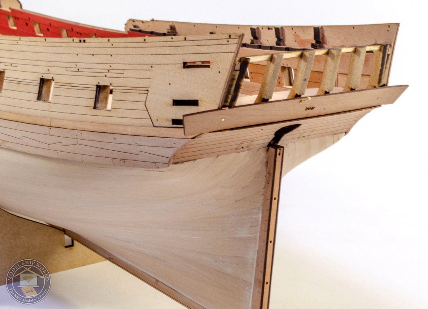
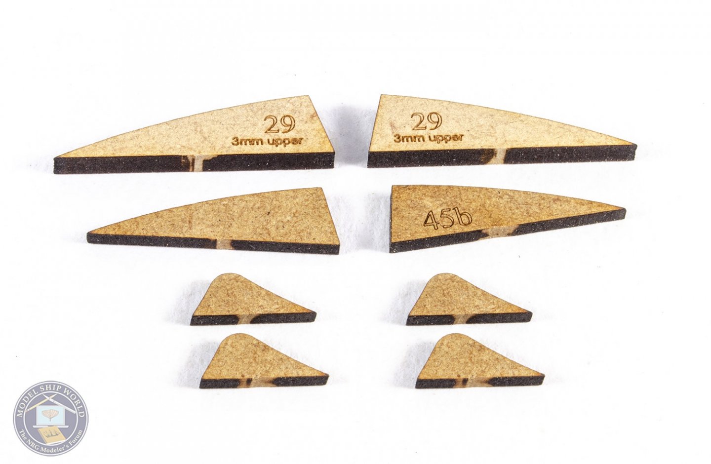
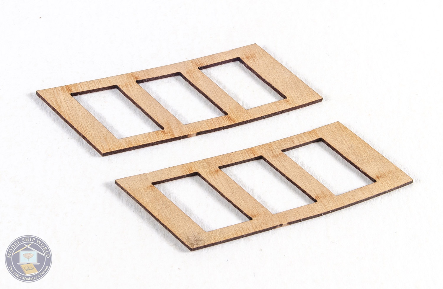
Now it's the turn off the quarter galleries to be fitted. The core of these are some MDF frame parts.
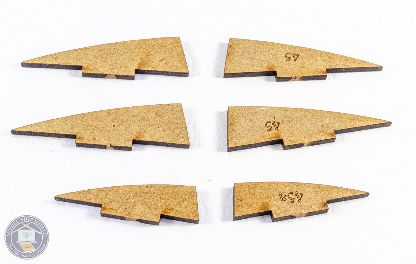
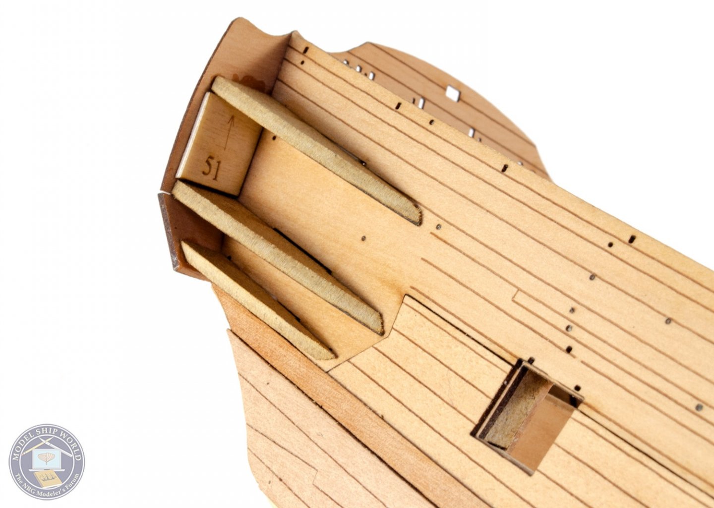
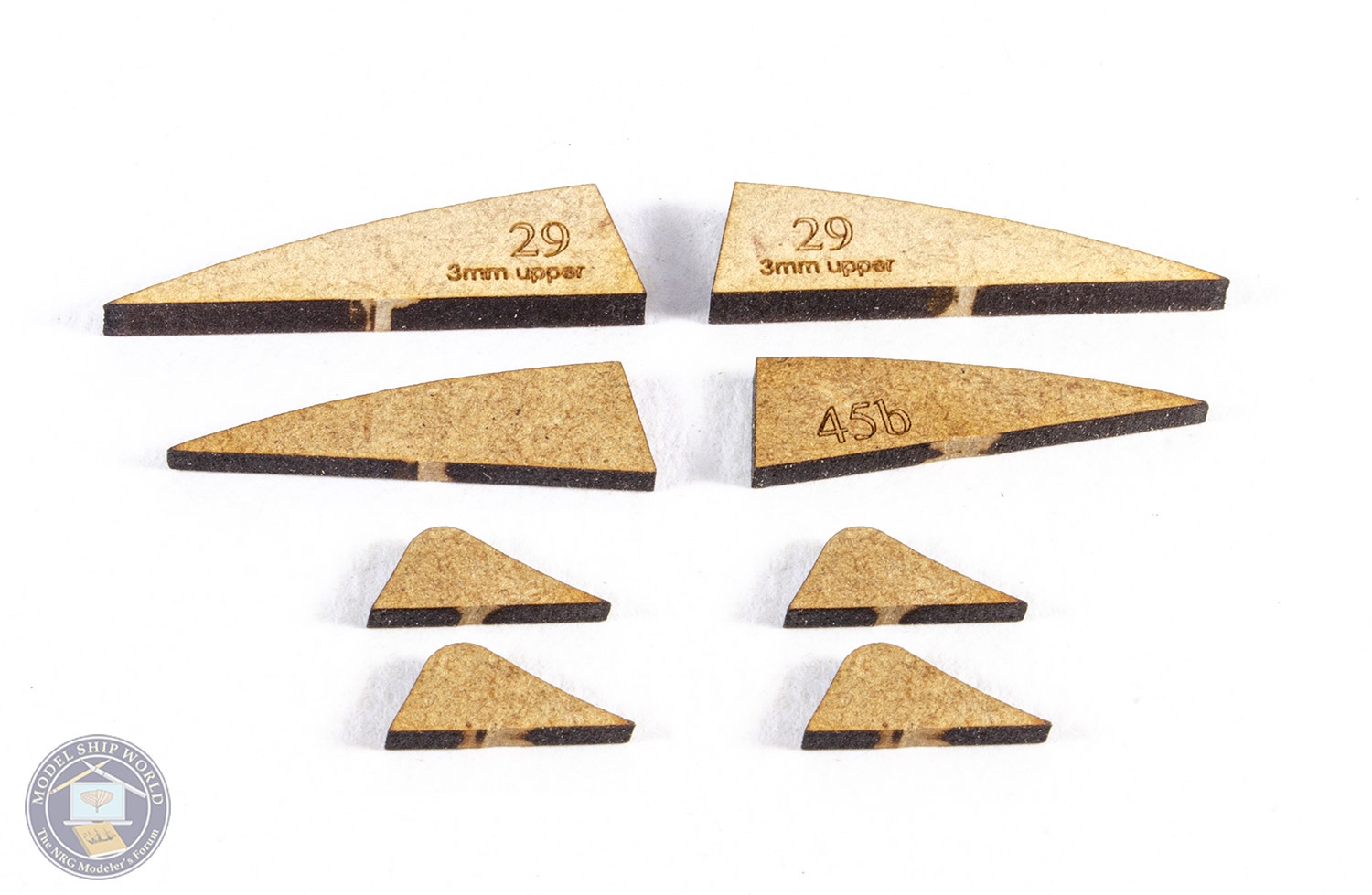
These are now fitted. Before gluing, they are trimmed at the rear end to the size of my particular build, and bevelled to match the angle of the stern fascia. The edges are bevelled to accept the exterior parts. This will be explained in the manual, and it's dead easy. All of these parts are supplied with extra material so there's no need to worry about things not fitting. Note also the small ply part (51) between the frames. This is there to get the angles of the frames to the hull, correct.
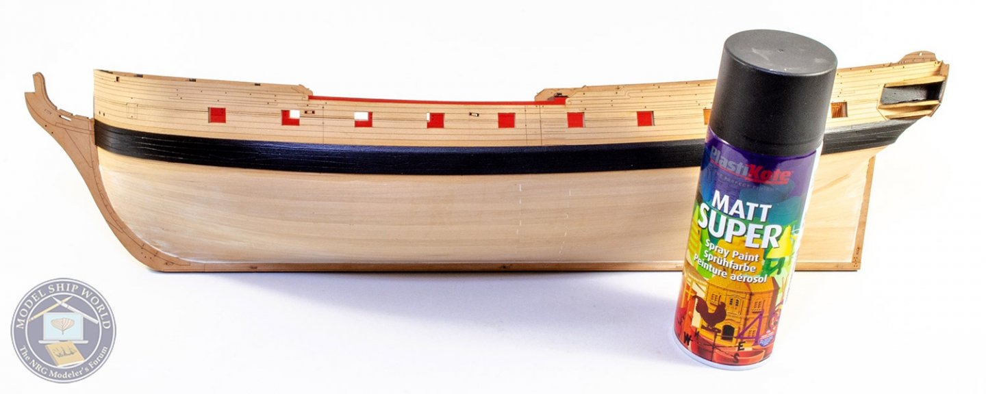
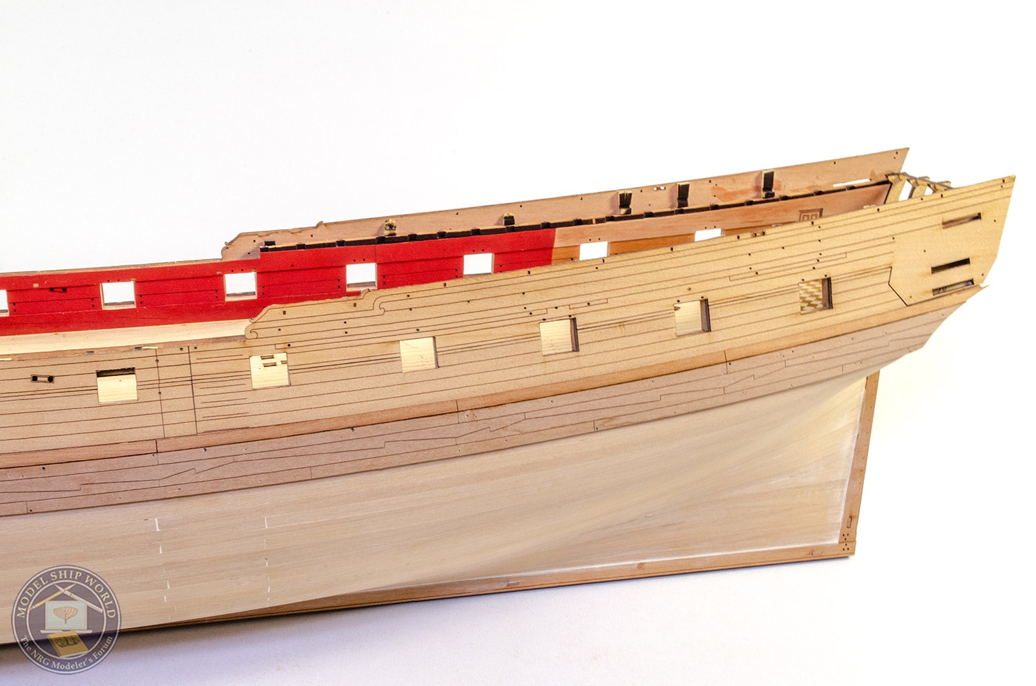
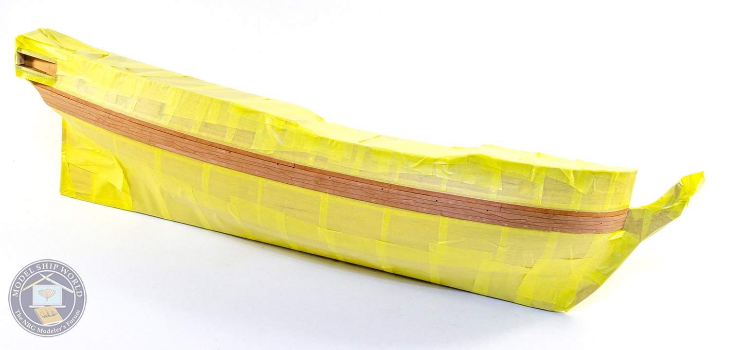
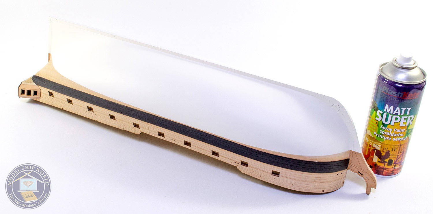
Now the gallery frames are fitted, the model is masked up so I can spray the wales and the inside of the upper quarter gallery areas. I used Plastikote aerosol to do this as the coverage is excellent and is ok straight onto timber.

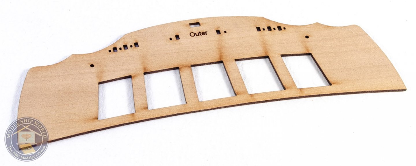
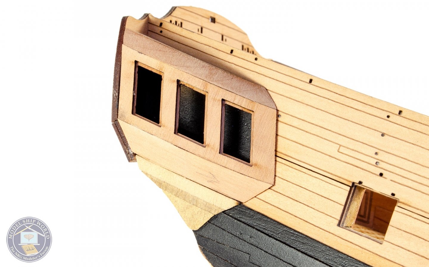
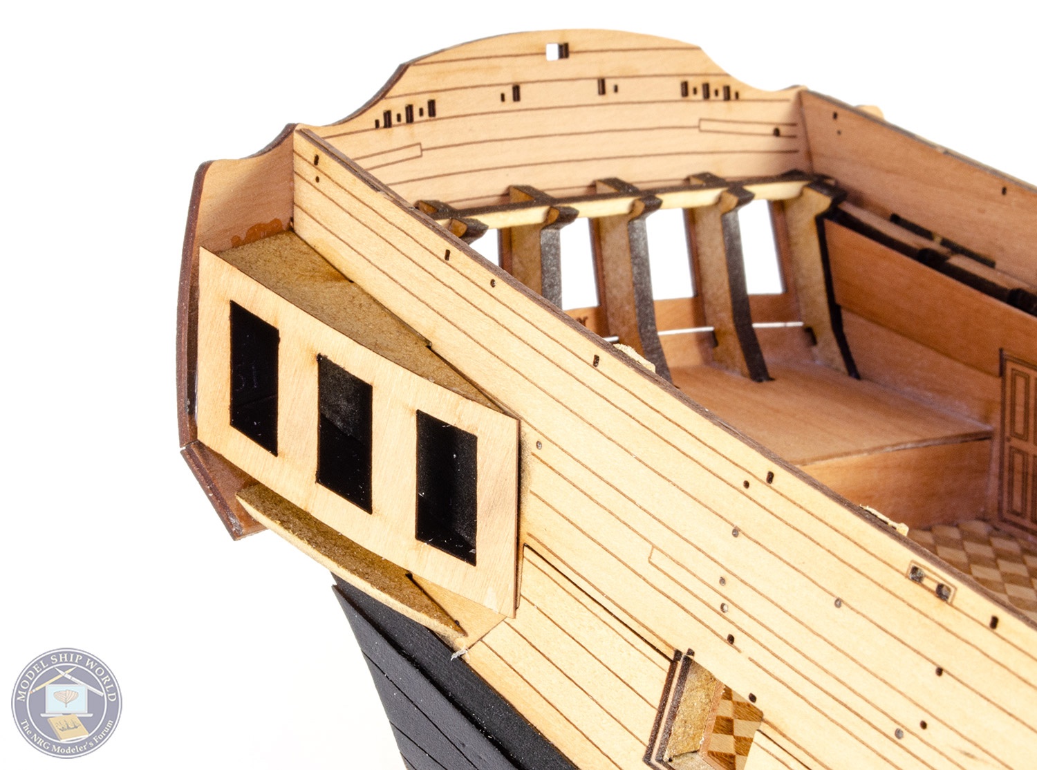
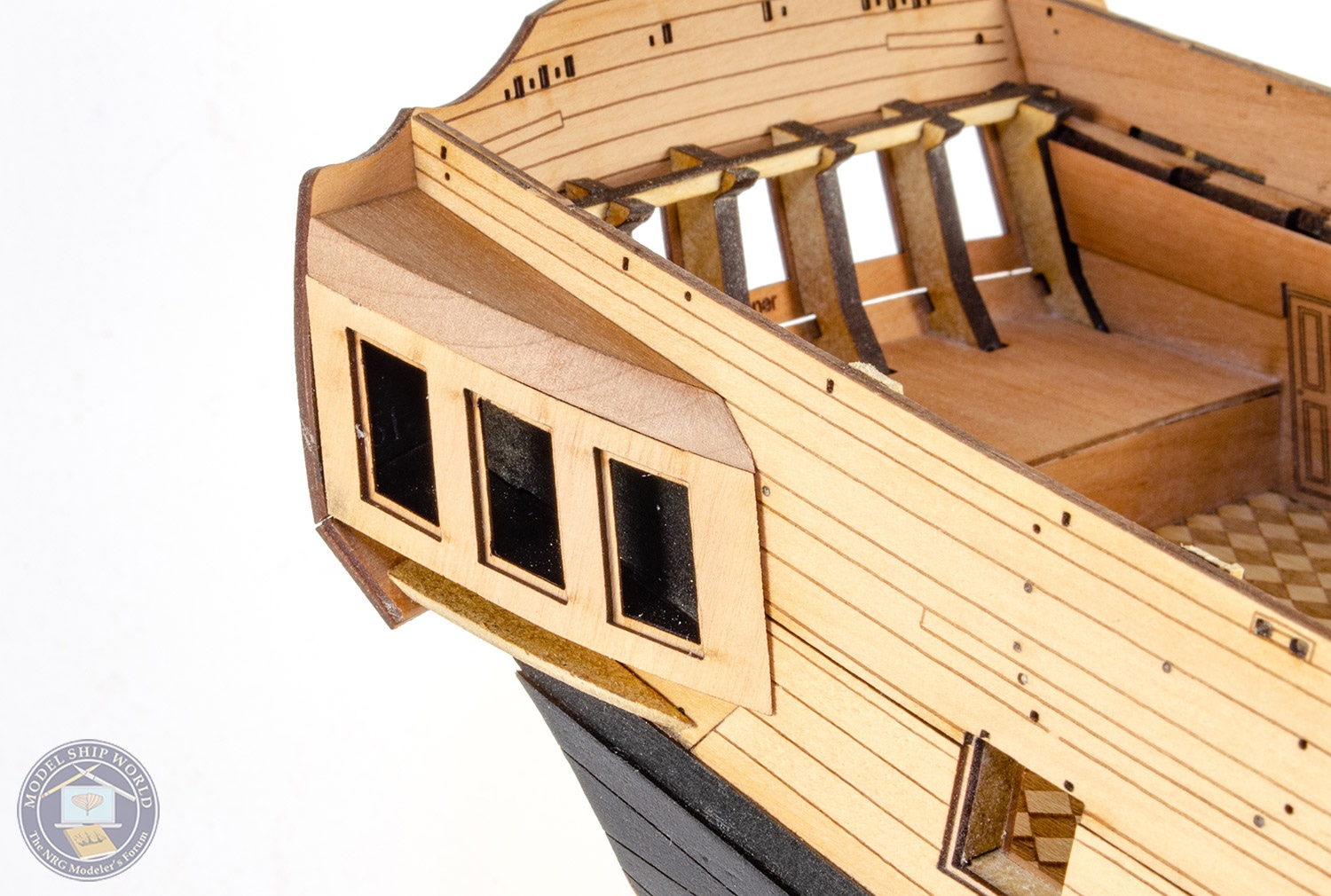
The stern upper counter and fascia outer panels are now glued onto the hull. Note how the outer fascia now creates rebates for the window glazing parts.

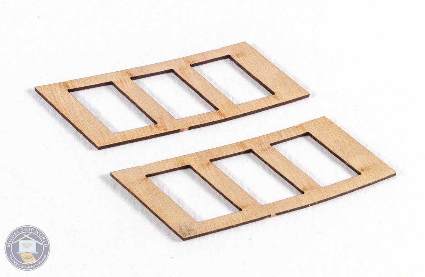
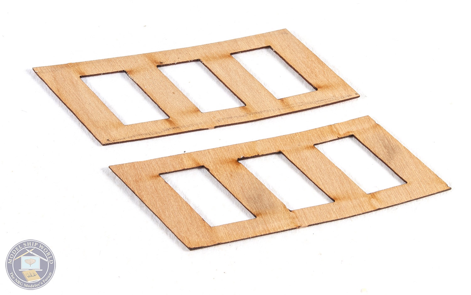
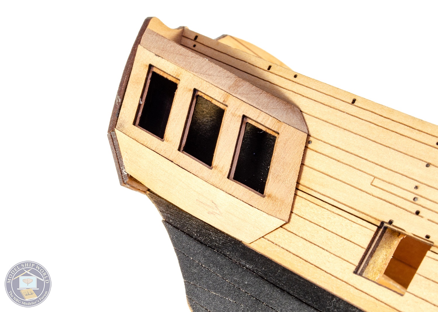
The quarter gallery window areas are constructed in the same way as the stern, with an inner part fitted first. Again, these parts have a little extra on the front and rear to cater to individual builds, and there will be little to nothing needed to be trimmed along the upper/lower edges. A thick pear 'roof' is then bevelled to the engraved line and these are fitted to the top of the quarter galleries.


The gallery berthing panels are now added below this.

MDF parts are now used to construct the lowest areas of the quarter galleries. These are assembled to each other on the model (but not glued to the model just yet), then set aside to dry. They are then shaped to match the gallery, checking progress by test fitting to the hull. Once shaped, some pint is scraped from the wales and the sections are glued into place.
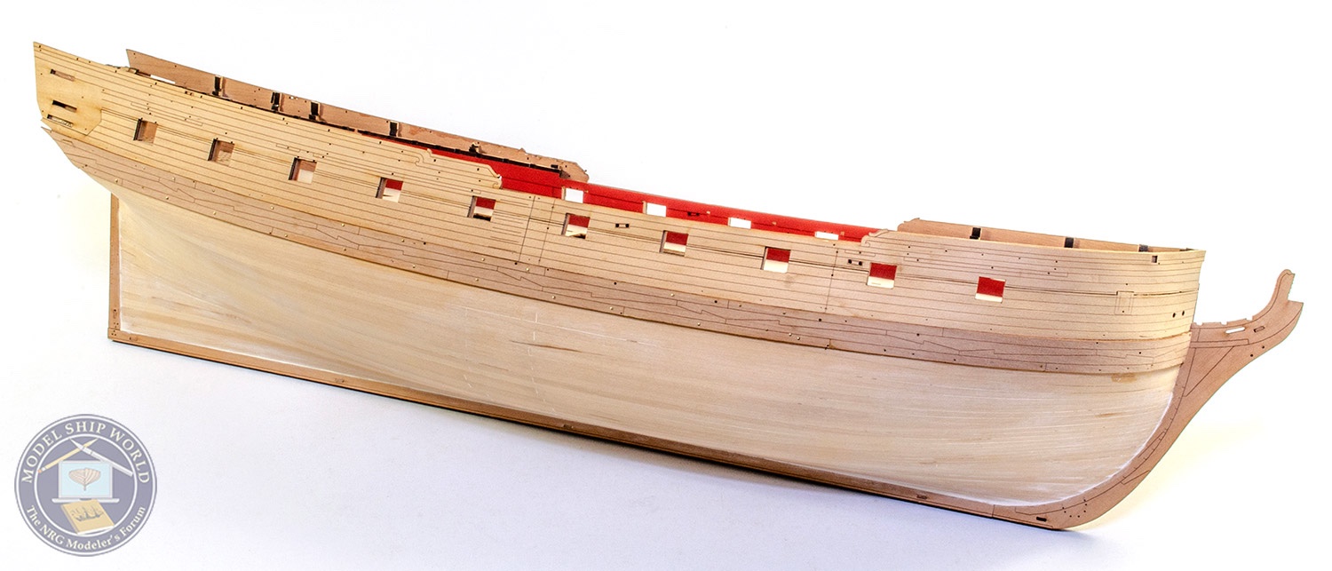
Out comes the waterline tool again. Checking this against the hull profile so both the prow and stern are at the same height, the line is added and the model masked again. More sanding, filling is then done. This took me about 4 days to get into a position where I was happy enough to paint.
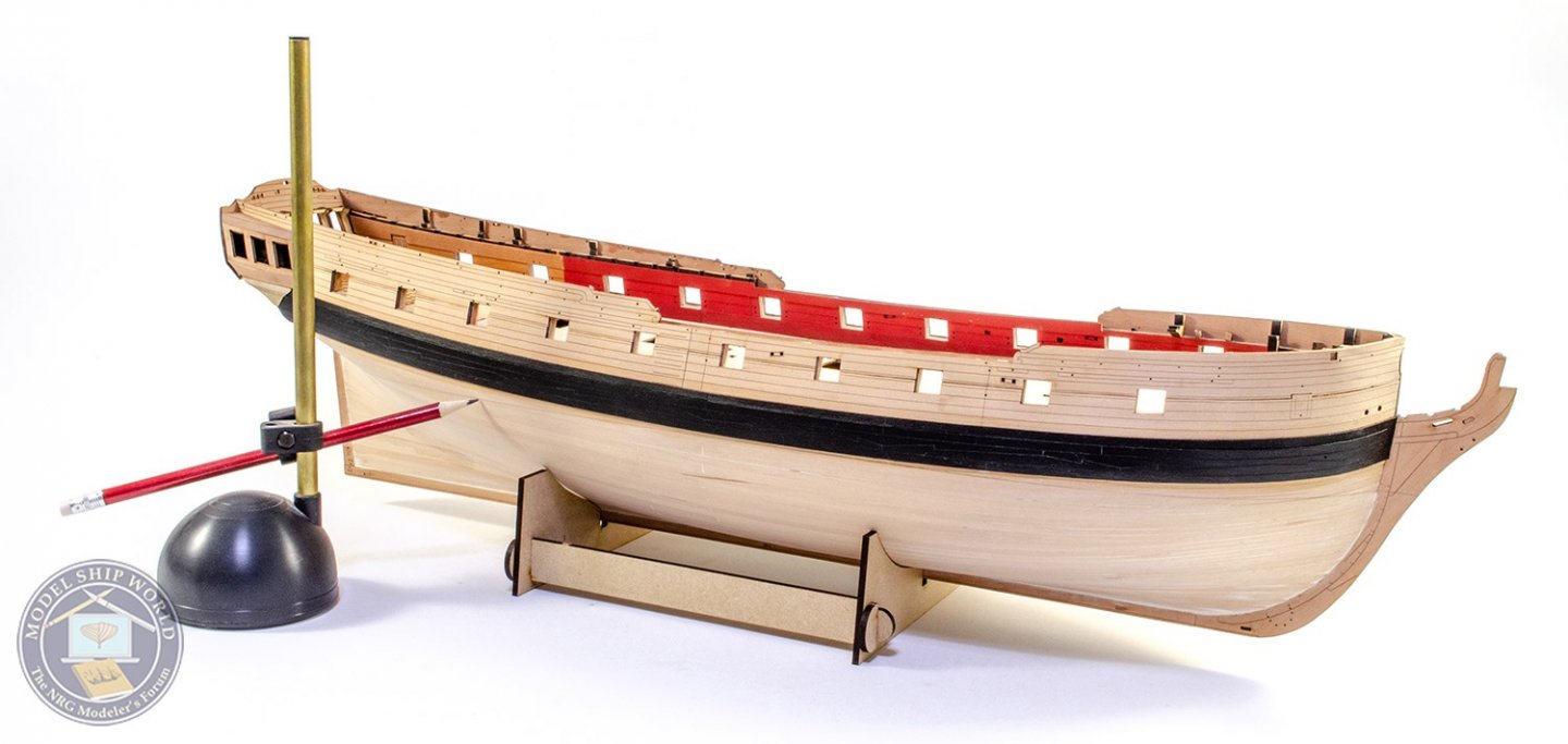

Plastikote White paint is now added. This is done in thin layers and more rubbing back and filling will need to be done to get a smooth, even surface. It is tedious, but the results pay off.

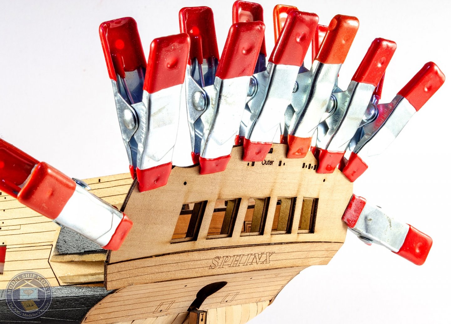
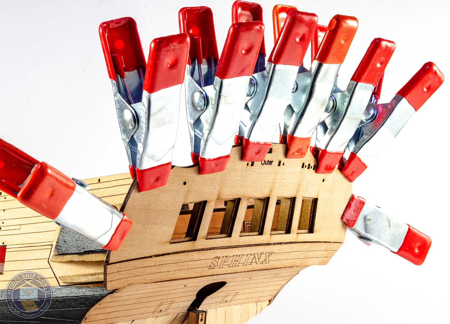
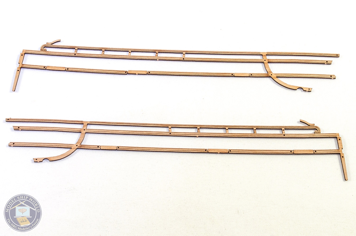
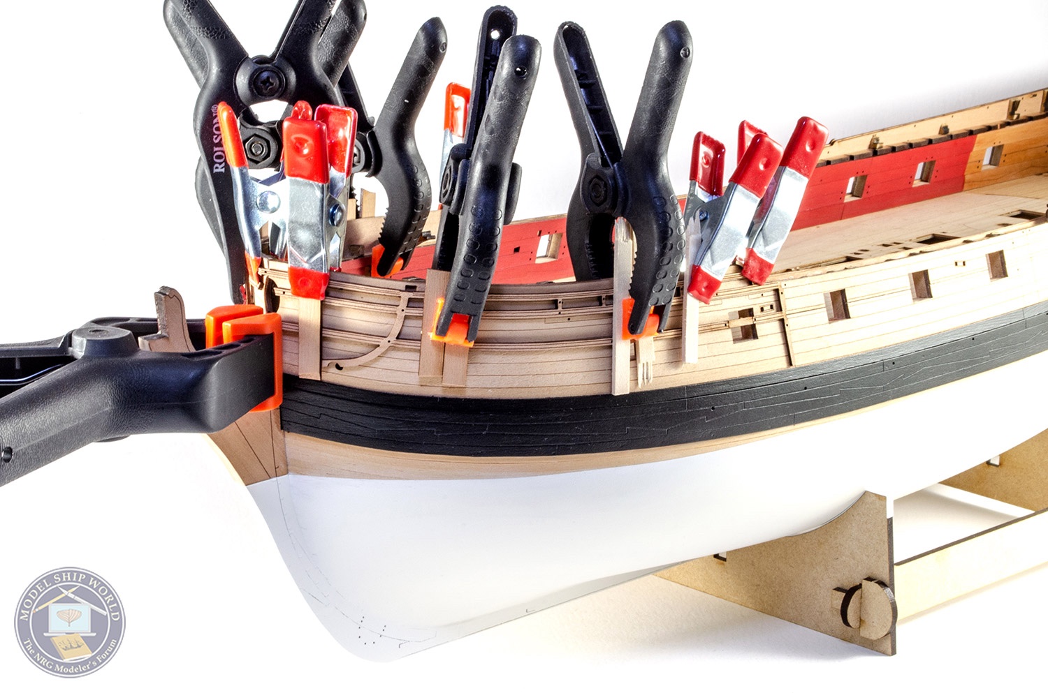
The last task I did was to take the bow rail patterns and soak these before clamping into position on the hull so they can dry in shape.
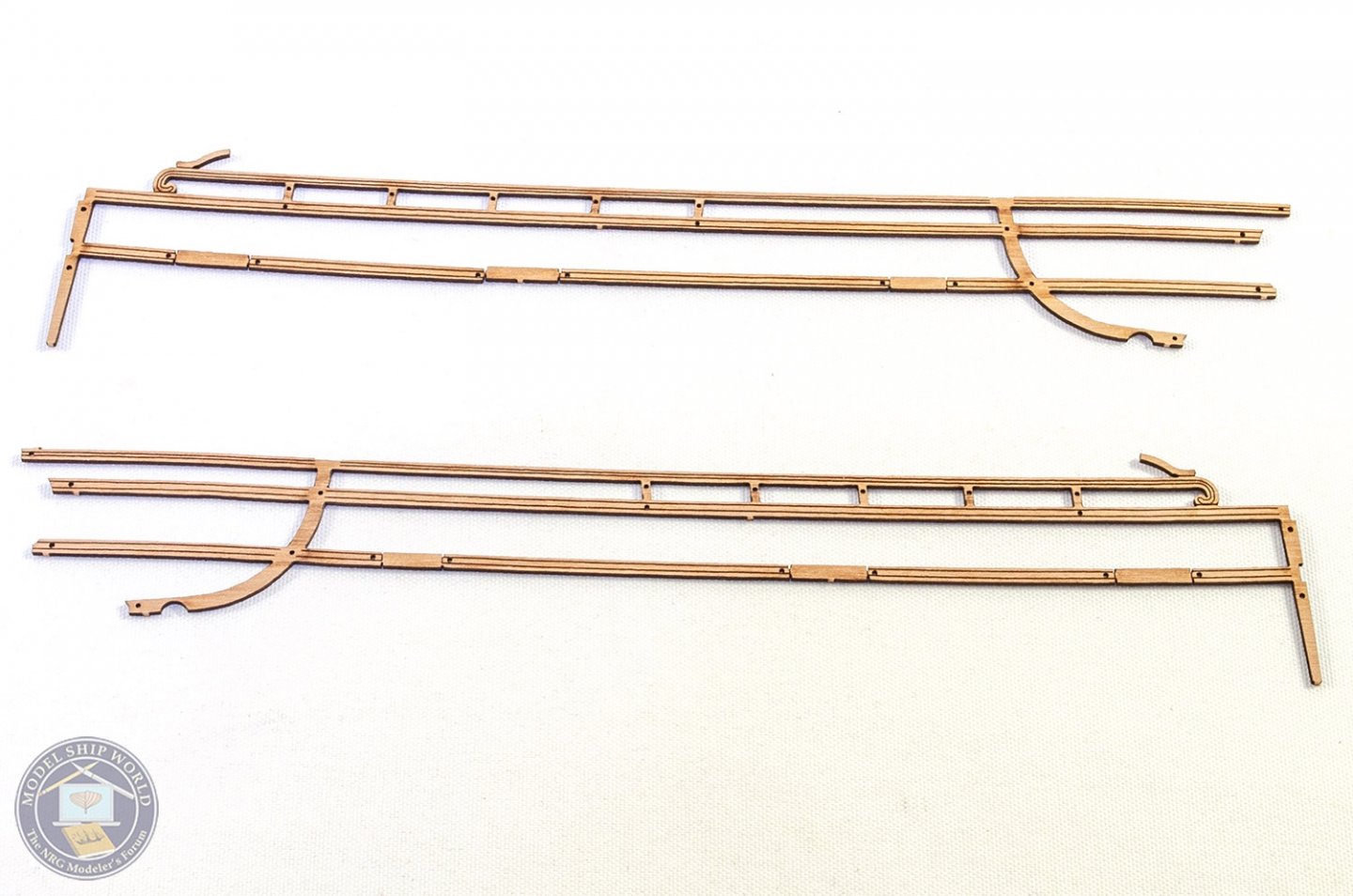

With these taken off, the hull can now be selectively varnished in places before applying the red, blue and black exterior panels. You'll see that in my next update.
-
-
Lovely work. Nice to see another of these being built.
-
14 hours ago, skipper1947 said:
Thanks for the replies guys. Chuck, I am afraid your Winchelsea looks a little above my pay grade. I guess when I said higher end, I was thinking along the lines of high quality components ready to be finished and installed. My tool set amounts to little more than a couple files and some xacto blades, which is in keeping with my manual dexterity.
As for what I would be looking for, perhaps a yacht from the early 1900s such as the Bluebird of Chelsea, and since I am fantasizing; with high end wood and fittings. I don't see myself tying any more ratlines any time soon.
Shame you don't want the ratlines, but this is a yacht
")
Can also be built with very basic, standard tools. Lots is pre-cut/pre-fabricated, engraved, and from pearwood. You can see a build log in my signature, and the instructions are downloadable to see first, from the website.
https://vanguardmodels.co.uk/product/duchess-of-kingston/
- skipper1947, Canute, GrandpaPhil and 5 others
-
7
-
 1
1
-
1 hour ago, aydingocer said:
I also got inspired from this review and bought this kit. Almost ready and looks like in the photo this at the moment.
I actually wanted to write this post for sending my thanks to Occre. There were a couple of missing parts and some wires supplied too short (though it is also possible that I might have lost the parts and used the wires a bit too generously), but they sent me the missing parts free of charge with no questions. It was as easy as filling a form on their page. The parts were in my post box within 2-3 weeks.
One recommendation to Occre; although the photos are detailed, they don't always provide sufficient information to see the exact assembly points at several spots. A sheet of drawing would be helpful. Depending only on the photos for building a model is not really a modeller's way.
Regards,
Aydin
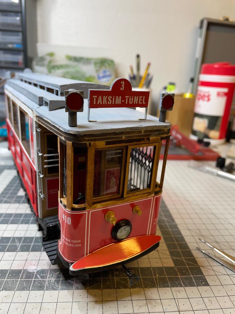
That turned out beautifully 🥰
- Canute, aydingocer and mtaylor
-
3
-
-
-
I think it's important that for a white backdrop, you buy something which is bright white.
For my use, I have a large card sheet called 'ice white' which is excellent. When I do larger photos, I draw down a vivid white roller blind as a drape. I still need to generally fix white balance in Adobe Lightroom, but it's pretty simple.
- Mark P, Rik Thistle, thibaultron and 1 other
-
4
-
9 minutes ago, mort stoll said:
How much of the stern cabins are going to be exposed on the completed model?
Thanks,
Mort
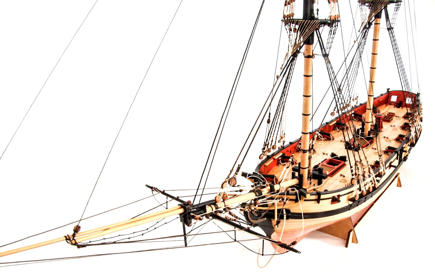
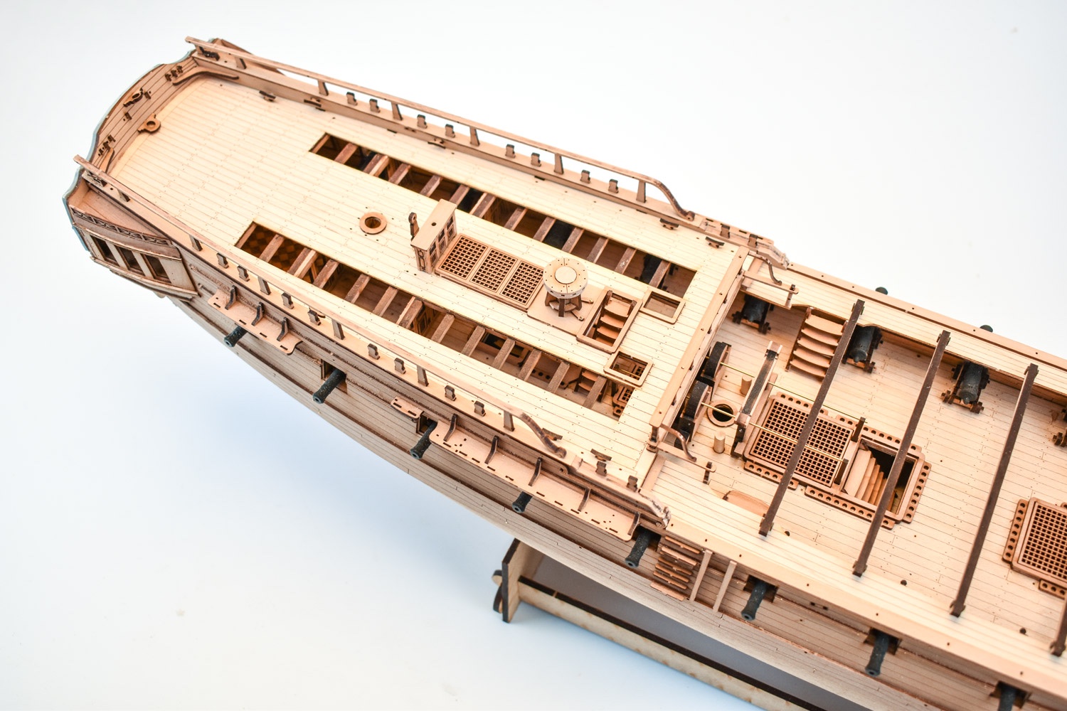
You'll be able to see into the cabins via the cutaways in the quarterdeck:

- gieb8688, mort stoll, marktiedens and 14 others
-
17
-
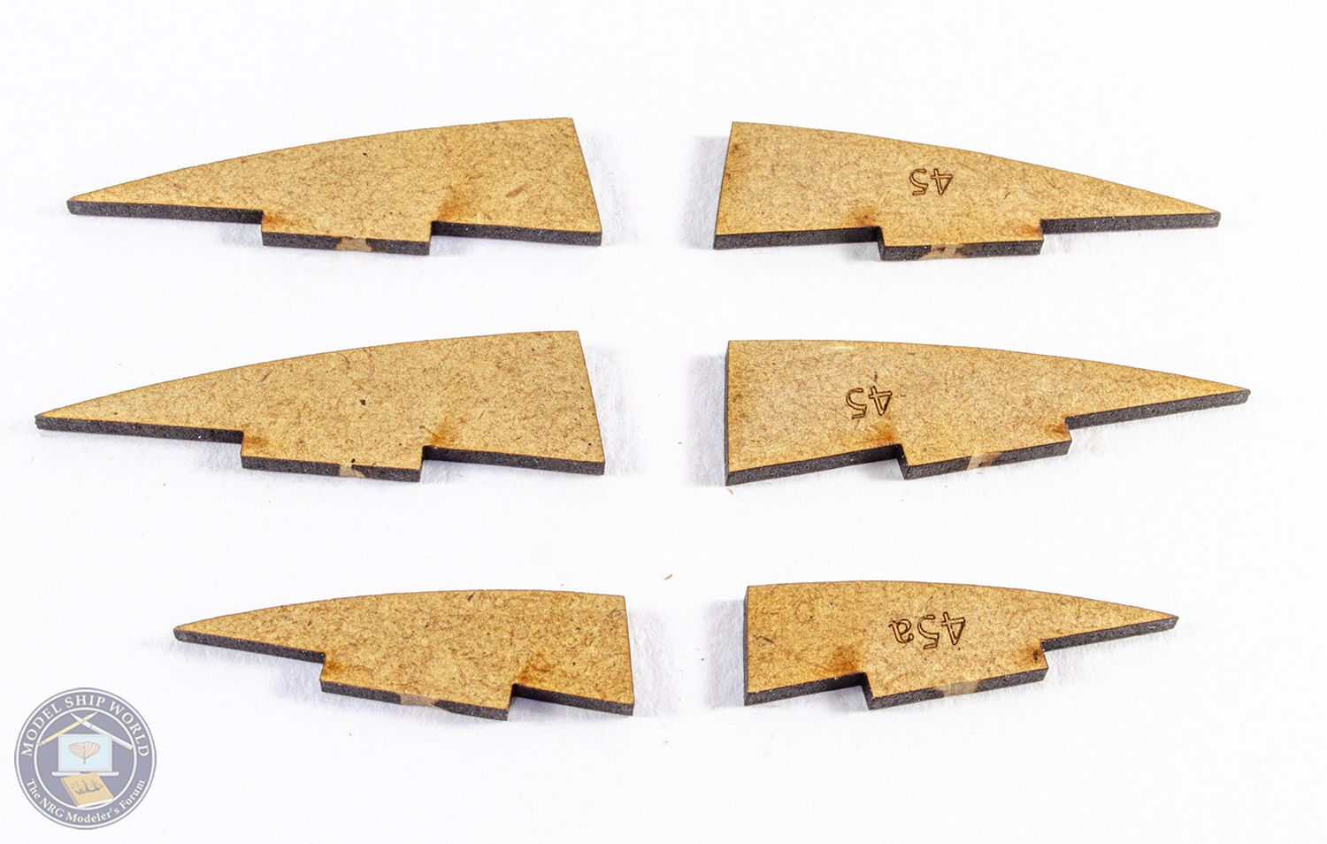
Prob going to be another week before I update. The engraved wales are now fitted and those needed to be altered slightly from the first cut parts, so little things like this need a couple of days lead time. I've just painted them black, and I'll be concentrating on the stern and underside this week, so there should be something worthwhile to show you in a week's time.
-
12 minutes ago, Captain T said:
Just now jumping in on this build log, looks amazing so far. Chris's designs are fantastic as is James's work. I just finished Pegasus and I'm really hoping this one becomes available in time for Christmas.
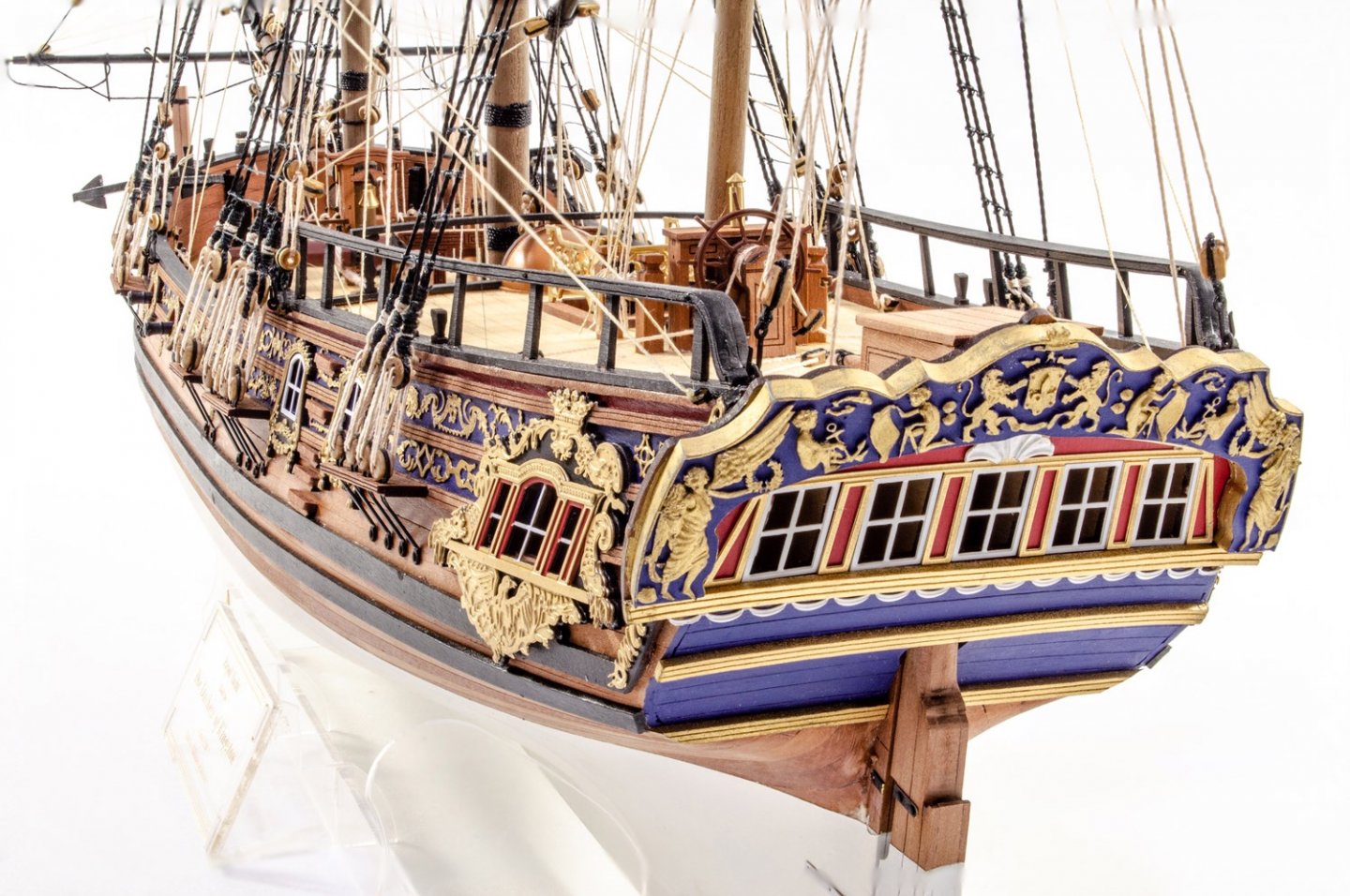
Question regarding the kit. Is the lettering for the ship's name on the stern counter photo etched parts? Curious about the font and size, etc, in case someone wanted to use the name of one of the other nine ships in the class like HMS Daphne or Narcissus for example.
Though now that I think about it, I suppose that also brings up the issue of modifying the figurehead as well...
Tony
If it's not ready for Christmas, Chris will kill me and probably never use my services again! 😆
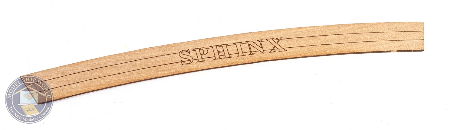
The stern lettering is PE, and sits above the letters which are engraved on the stern counter.
- Ryland Craze, glbarlow, Canute and 7 others
-
10
-
-
8 hours ago, mtaylor said:
Just curious, James on the shoulder harness. I take it the instructions don't show the shoulder harness connected to the lap belts? If I remember right, they were on all the cars of the period. It's still a beautiful build.
I would've thought so, but I'm not too sure. Just building it as per instructions.
- Old Collingwood, Canute, Egilman and 2 others
-
5
-
4 hours ago, jep1210 said:
Wait, there's a micro switch on the accelerator pedal? 😲 That means push pedal get engine sounds???? 😍
Sure is, as well as horn sound, working lights etc.
-
21 minutes ago, JohnU said:
Whoa, I didn't mean to start a flame war!
Don't worry, you didn't.
- Canute and Keith Black
-
2
-
30 minutes ago, rshousha said:
Race to the bottom. Let's all run to Cornwall models and throw our local hobby shops under the bus.
Taking this a little further, why buy from Sherline when Chinese copies are cheaper? Why buy from Proxxon when Chinese imitations are cheaper?
Oh well.
You're lucky if you have a local hobby shop.
Most I know of succumbed in the 1990's/2000s, let alone any that would ever sell anything as niche as wooden ship kits or the accessories needed to build them. Even when my little town had 4 hobby shops in the 1980's, and as many others that sold hobby stuff as a sideline, there was never even a sniff of wooden models.
You know, Manchester (UK city) doesn't even have a model shop any more....and you'd think a city that size would have several. Nope. The last, Manchester Models (Deansgate) disappeared a good few years ago.
When it comes to model ships/boats, it's generally the internet that's keeping us going.
-
STAGE 52, 53, and 54: DRIVER BUCKET SEAT, DRIVER SEAT BOTTOM, DRIVER SEAT COVER, SEAT BELT AND SEAT-BELT HARNESS

For the sake of repetition, the next seat is built up in the same way as the previous.

The two seat belt hooks are now pushed into position, and the belts fastened to them.


Both seats are now secured to the interior via screws from the underside.


STAGE 55: TRUNK BOARD AND TANK FILLER PIPE


This one is dead simple. The tank filler pipe is secured to the truck board with a single screw.

STAGE 56: CIRCUIT BOARD AND ELECTRICAL CABLES


There's no actual electronics work involved with this, or testing. Each lead needs to be plugged into the socket on the circuit board that has the same number, When complete, the circuittboard is fastened to the trunk board.


That's all for the moment.
-
Onwards with Pack 7!
It really doesn't seem to have taken long to get to this stage. Quite a simple pack this month that concentrates on the interior, so we can 't yet cure the wobbly front wheels on the main chassis. 😜 I've put some stages of this pack in the same sequence as at least 3 stages contain zero work.
STAGE 49 & 50: BUCKET SEAT/PASSENGER SEAT COVER, SEAT BELTS AND SEAT-BELT HARNESS


First up, the double-sided 3M tape is cut to size and stuck in position on the plastic seat, like this. I ignored the instruction to cut to 4 lengths the same size as you really need to cut them to the actual size needed. The front tape lengths are then trimmed to shape.

After peeing off the outer tape paper, the seat cover is slid over the plastic seat and then the sides pulled in so the tape fixes them in position. This is a little awkward, but works quite well.


With the seat cover in place, the seat cushion from a previous pack is then screwed to this, holding everything in place.


The lap belts are now pushed onto the lugs on the seat underside. These hold the parts real well, and I found no need to add any glue.


STAGE 51: BATTERIES, BATTERY CABLES & CUT-OFF SWITCH


Both batteries are plugged onto the mounting unit. These can only fit one way. Two screws hold them in position.


The battery unit is then screwed into position from the underside using 4 screws.

Both battery cables are then connected to the power shut off device, and this is then secured to the interior.


Both batteries are then 'wired up' like this. One cable will flap around, but that seems to be normal and it will be hidden behind a seat. Note I removed the gear stick too. That's to stop me damaging it. I'll replace it later in the build.

The battery holder is now pushed into place. No screws required.

- Ryland Craze, Canute, mtaylor and 5 others
-
8
-
18 minutes ago, JJT said:
That looks to be quite a large model.
3ft tall (half scale) and weighs about 13lbs
- Old Collingwood, Canute, mtaylor and 4 others
-
7
-
STAGE 96: ADD THE LEFT KNEE CAP AND ASSEMBLE A TOE

The two kneecap parts are glued together and then the part glued to the leg.

And the construction of the toes also begins.

STAGE 97: BUILD PART OF THE LOWER LEG, AND A SECOND TOE

The lower led is now started, and another toe built.

STAGE 98: CONSTRUCT THE THIRD TOE, AND EXPAND THE LOWER LEG ASSEMBLY

More work on the lower leg with the attachment of muscle pistons, and another toe is born.

STAGE 99: BUILD A FOURTH FOOT PART AND ASSEMBLE THE LOWER LEFT LEG

The outer shin is now attached to the lower led....and another toe in the series is built.

STAGE 100: ASSEMBLE THE LEFT FOOT AND ATTACH THE LOWER LEFT LEG

After building the last toe, then can all be fitted to the foot. It's vital to check the toe orientation and position from the instructions or it'll just look weird. I know as I did it upside down the first time. First, the lower toe joints are secured to the lowest point on the front of the foot, then the upper rods fasten to the connection above this.


The lower let is now fastened to the T-800 with a single screw. As there is a ratchet disc on this, it can also be posed at the end.


Until Pack 11....that's it. 😃
- Egilman, Canute, Old Collingwood and 7 others
-
10
-
Well, we are now onto Pack 10.
At this stage, the model is extremely heavy and not so easy to manoeuvre for photographing! I'm also more wary of just lifting this thing by the chest cage and now grip by the pelvis too so I don't put any unnecessary strain on the model. Everything seen in this pack is just a reproduction of building the previous lower leg and foot, so these pics just show the key assemblies.
STAGE 91: ASSEMBLE A MUSCLE FOR THE LEFT THIGH

Muscle piston! All glued parts use CA gel. If there was a lot of chrome plate, I first rubbed each joint with some fine abrasive paper to provide a better key for the glue.


STAGE 92: KNEE, MUSCLE, AND FOOT: MAKE PROGRESS ON THE LEFT LEG

These are the three assemblies built for this stage; knuckle joints for the foot connection, muscle piston, and a knee joint with a ratchet wheel glued into position.

It really isn't easy flipping the T-800 over, but it needed doing! The thigh muscles are now screwed into position.

STAGE 93: BUILD OUT THE FOOT, AND CONSTRUCT ANOTHER MUSCLE

A nice, simple one. Another muscle piston, and screwing the foot section to the previously build foot assembly.

STAGE 94: AFFIX THE LEFT THIGH MUSCLE WITH NEWLY-CONSTRUCTED TENDONS

The other muscle piston is now fitted to the thigh, then connected to the other muscle and screwed through the thigh frame.


The ankle ball joint is now fitted to the foot underside.

STAGE 95: ASSEMBLE AND AFFIX A KNEE JOINT

If only a knee replacement was so simple! The knee joint is fitted with the ratchet discs and muscle piston.

This is then dropped into position and the knee end caps pushed into position and tightened with a hex screw. This can be adjusted to pose the T-800 when complete.

...and a little more work on the foot with the piston connectors and ankle joint.

- Rik Thistle, GrandpaPhil, lmagna and 6 others
-
9
-
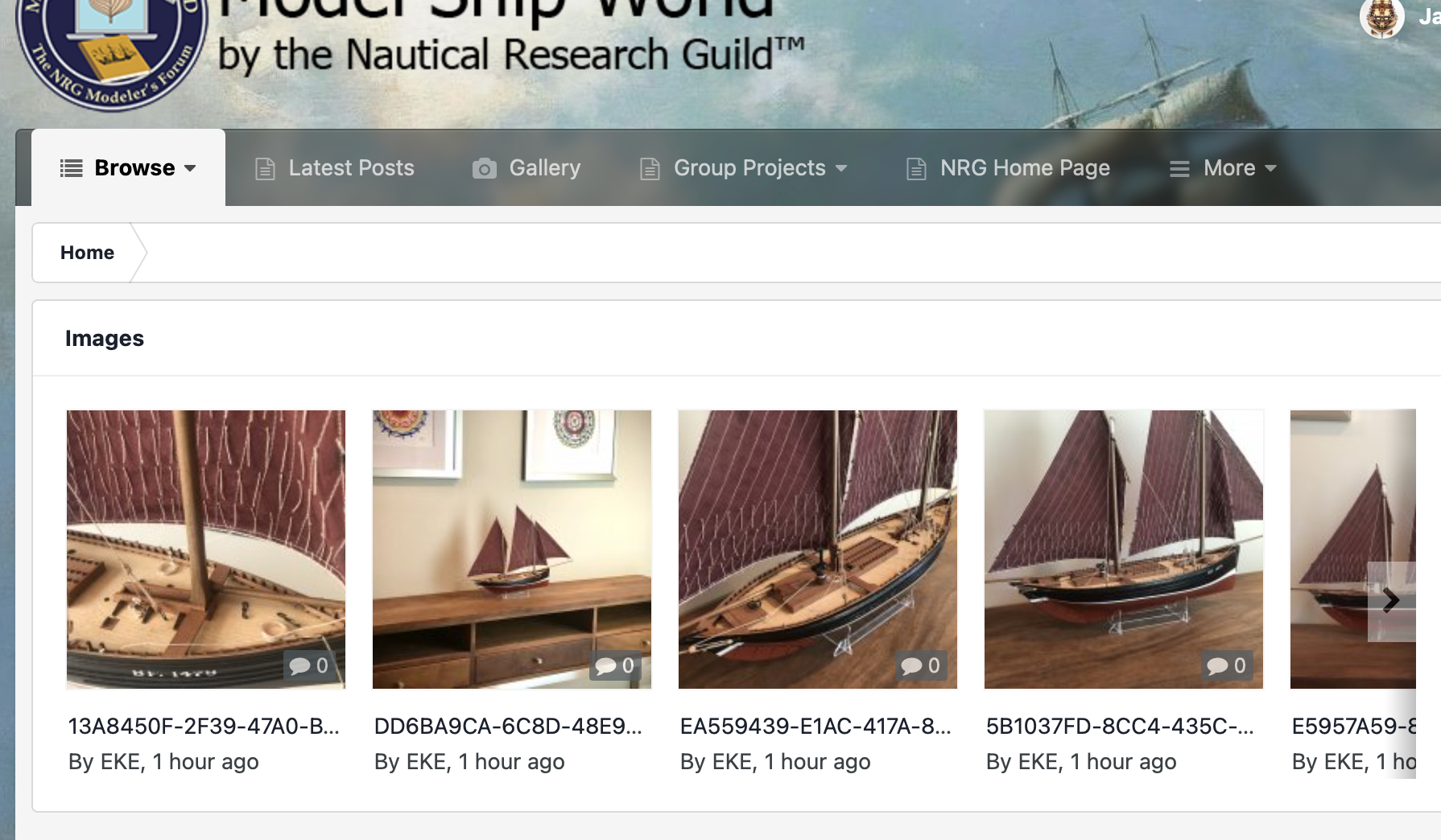
1 hour ago, EKE said:
James- Just created a gallery for Fidelity. Thanks for the prod, mate.
")
Cheers, that really is a beauty. Now I see her when I visit the site 😁

- EKE, BobG and Ryland Craze
-
3


HMS Bellerophon 1786 by fake johnbull - Amati/Victory Models - 1/72
in - Kit build logs for subjects built from 1751 - 1800
Posted
Beautiful work and some nice info too re: skid beams.