


gjdale
-
Posts
4,825 -
Joined
-
Last visited
Content Type
Profiles
Forums
Gallery
Events
Posts posted by gjdale
-
-
Bob - next up will be my Amati Hannah Ship-in-a-Bottle kit that I received for my Birthday a couple of months ago. But first I have some full size woodwork in the queue. I’m attending another one week hand tools master class next week, and I also have to make a document box that will be a wedding present for my son and his fiancé, who are getting married at the end of next month. I’m starting on that one today.
- mtaylor, Rustyj, usedtosail and 2 others
-
 5
5
-
-
-
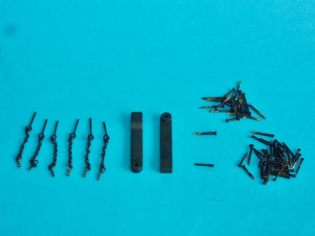
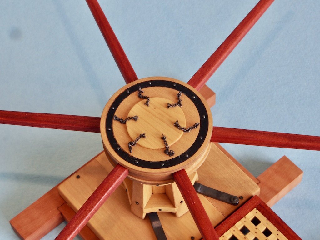
Metal work and Blackening
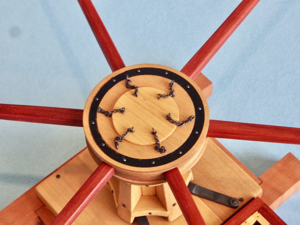
I decided to “cheat” when it came to the bolts and have used two different sizes of brass nails left over from kits various to represent all of the bolt heads. Similarly, left over eye bolts were used for the bar retaining pins, and I found some chain sculling around in the spare parts box as well. The only thing I did make were the eyebolts that secure the bar pin chains to the centre of the drumhead.
There have been many discussions on this forum regarding blackening and I have tried various of them over the years. For blackening brass, my go-to product has become Jax Pewter Black, which claims to work with pewter, lead, brass, bronze, copper, tin-lead alloys, and solders. The key to success with this product (for me) has been to NOT dip or soak the parts to be blackened in the solution. Rather, by using a small bristle paint brush, the solution is “rubbed” onto the surface of the part, and then rinsed in distilled water. By using this method, I have found that the blackening does not flake or rub off. Here are all of the metal parts blackened and ready for installation. For the nails/bolts, only the heads needed blackening as the rest won’t be seen.
Final Assembly (P/N 1000)
All of the wooden parts received two coats of Kunos Oil, wiped on and buffed off immediately. This has left a smooth to the touch finish without too much sheen (more coats = more sheen). With all the metal work blackened, final assembly was a pretty straight forward process. I opted to use 5-min epoxy to secure all of the bolts etc, rather than CA (which I really hate using).
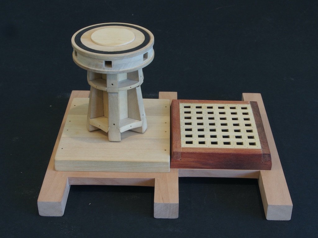
So here are some final shots of the completed project:
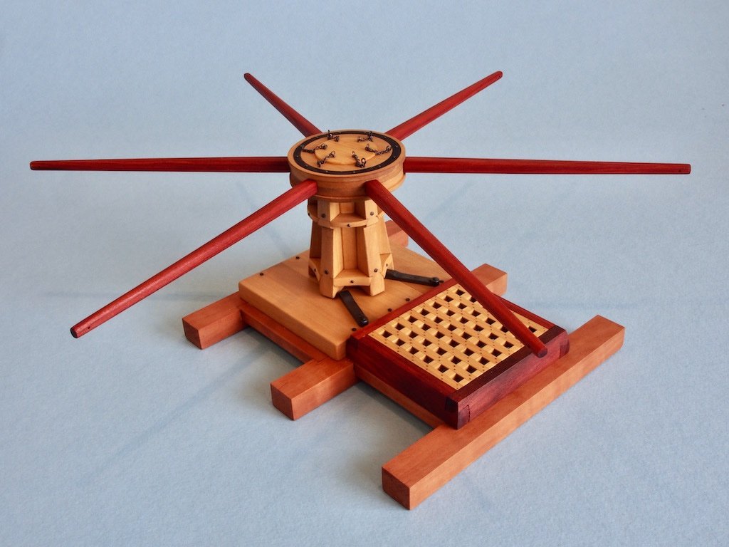
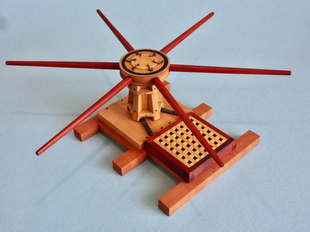
This has been a fun little project that presents more than a few challenges for modellers of all capabilities. I’d like to thank Toni for all her work in making this project available. I'd also like to make a special thanks to Tom (Used to Sail), whose log was a great source of additional information, as well for the occasional PM conversation along the way. Thanks also to all who have stopped by, offered kind comments and/or hit the like button.
-
Randy,
I have to agree with Ed - more sophisticated tools are more capable (and more expensive) buy aren’t the panacea to all your modelling problems. That said, I’m very biased towards the Sherline lathes and mills - they are a joy to use and do enable you to produce some excellent results - BUT - they also often require a good deal of thought about the process by which you achieve those results. For me, it is often the challenge of how to hold the workpiece for a particular operation that takes the most thinking. I often go searching through logs like Ed’s or Danny Vadas’ looking for ingenious solutions to these problems when they arise. I then try to replicate what they have done. Occasionally, I’ll come up with my own ideas too.
Only you can decide whether to return/replace your current tools, Should you decide to do so, my recommendation would be to look at the Sherline range. Yes, they are expensive, but as my dear old Dad often said, “quality is remembered long after price is forgotten”.
-
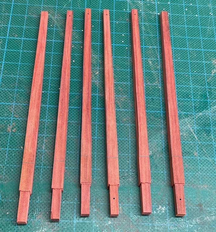
Capstan Bars (P/N 034)
The Capstan Bars are relatively simple to make. I am using Red Heart for these (the same timber as used for the hatch coaming). After cutting the blanks to size and finessing with the Byrnes drum sander to ensure all pieces were the same thickness all round, the tenons were cut on the mill and while I was at the mill, drilled the holes for the swifters.
I tested some options for cutting the tapers, including a full-size edge sander (not enough control), the tapering jig for the Byrnes saw (could only do two adjacent edges, and even then, the length of the pieces made this very awkward and a little dangerous for my liking). In the end I settled on my Proxxon belt sander. I bought this tool quite a few years ago and have never used it very much at all. It turned out to be ideal for this particular job.
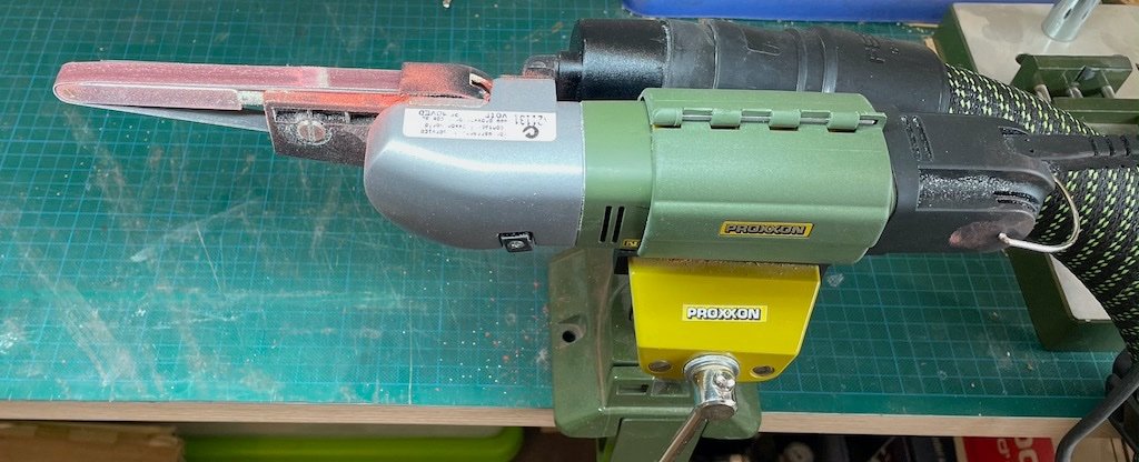
It had the added bonus of being able to be hooked up to a vacuum hose, so I brought my Festool shopvac inside (while the Admiral wasn’t looking) and made quick work of the tapers.
Final rounding and smoothing was accomplished with a combination of a modellers’ rasp, a soft sanding block, and a sanding sponge – no pics of this stage.
All of the parts have now been given a first coat of oil. All that remains now is to blacken and then install the hardware. Final pics once that has been done.
- JpR62, Cathead, usedtosail and 8 others
-
11
-
Randy,
Your lathe is a wood lathe, hence the rest. Ed uses a lathe designed for metal working, hence the “clamp”, which is the tool holder. These are two very different beasts. With wood turning lathes, you hold the tool by hand to work the piece. With metal turning lathes, the tool is usually held in a tool holder, although you can add a wood turning rest if you desire (Sherline for example offers this as an accessory).
-
-
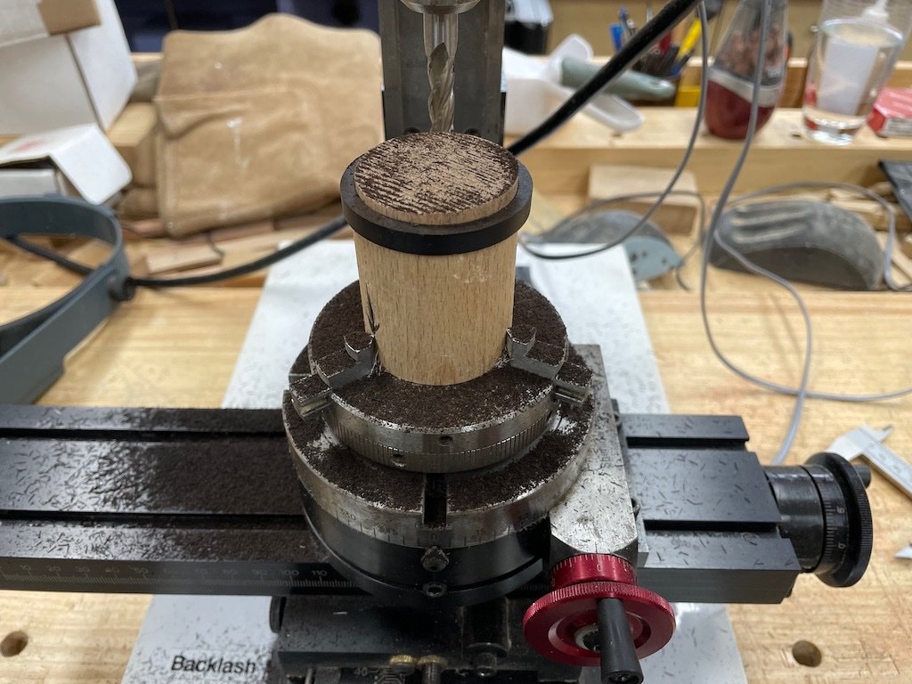
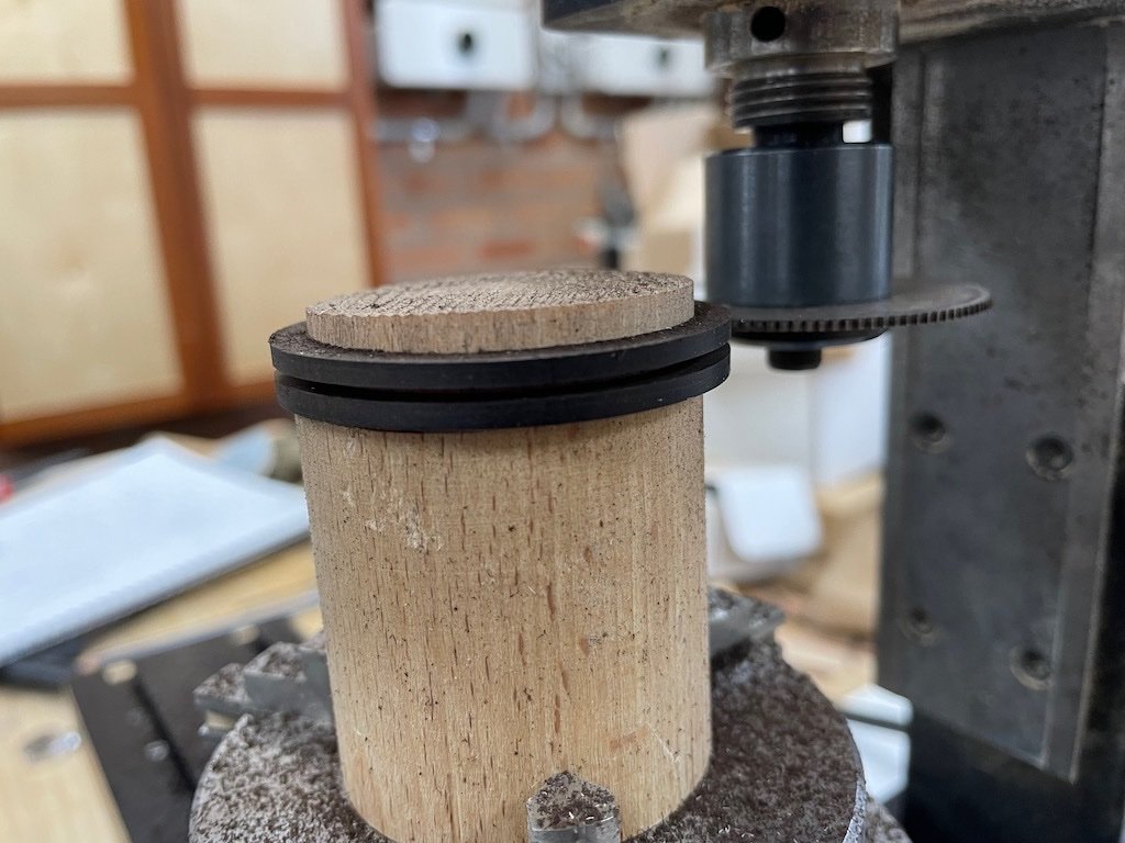
After separating the two halves of the drumhead, they were individually re-mounted to the holding cylinder to have the rebate for the iron ring milled. Each was then de-bonded, flipped, re-glued to the holder and the slots for the capstan bars milled. The drawings show these as 3.25” wide by half that in depth. At scale, that translates to 13/64”. Again, my choice of end mills was limited, so I opted to go with 3/16” (12/64”).
Here is a shot of the milling set-up after completing the capstan bar slots, but before cleaning up the “fuzz”.
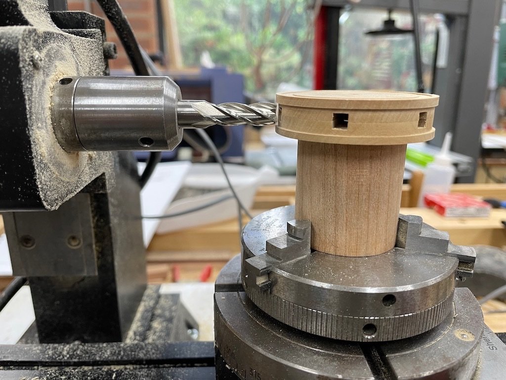
Once both halves had been milled and cleaned up, they were temporarily glued together for the next milling process. Again, my alignment strategy paid off. Here is the drumhead mounted back on the mill – in this shot you can see the rebate for the iron ring milled in the previous process.
To mill the rebate in the sides, the mill head was rotated 90-degrees to the horizontal position. It may just be me, but I couldn’t identify from the drawings what the depth of this rebate should be, so I just went with what looked “about right”.
Iron Rings (P/N 020)
The next task was to make the iron rings. There are two of these required – one each for the upper and lower drumhead. I thought long and hard about whether to use brass or wood for these parts, as well as a process by which to make them. In the end, I opted to go with wood as I had some pieces of ebony that I thought would fit the bill.
I began by milling the rough stock to a 6mm thickness. I chose this thickness as I was concerned about very thin pieces self-destructing in the fabrication processes to follow. I then placed blue painters’ tape on one surface and drew two concentric circles to represent the inner and outer edges of the iron rings. Happily, the diameter of the inner circle was 1 5/8”, which just happened to coincide with one of my Forstner drill bits. The centre hole was therefore drilled first, and then the outer diameter was cut to rough shape on the band saw and refined slightly at the disc sander. However, to get the degree of accuracy required, it was necessary to find a way to mount the part on the mill. To achieve this, I took a scrap of thick dowel (actually an old rolling pin), mounted it in the lathe chuck in the mill, and gradually reduced a section at the top until I was able to fit the ring part over it with a snug “push” fit. By having such a snug fit, I was able to complete the milling without having to glue the work piece to the dowel. I gradually reduced the outer diameter with very light cuts (0.1mm at a time) until the part would fit into the pre-milled rebate in the drumhead. Here is a picture of that process under way.
A slitting saw was then mounted in the mill and again using light cuts and the rotary table, I was able to cut the 6mm thick piece into two 2.5mm thick rings (I used a 1mm thick slitting saw for stability).
Here is a shot of this part of the process underway:
And at the end of the process:
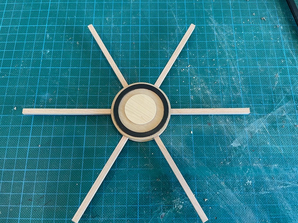
Here is a shot of the rings test fit into the drumheads:
And a test fit with some spacer bars and the Cap (P/N 021) temporarily in place.
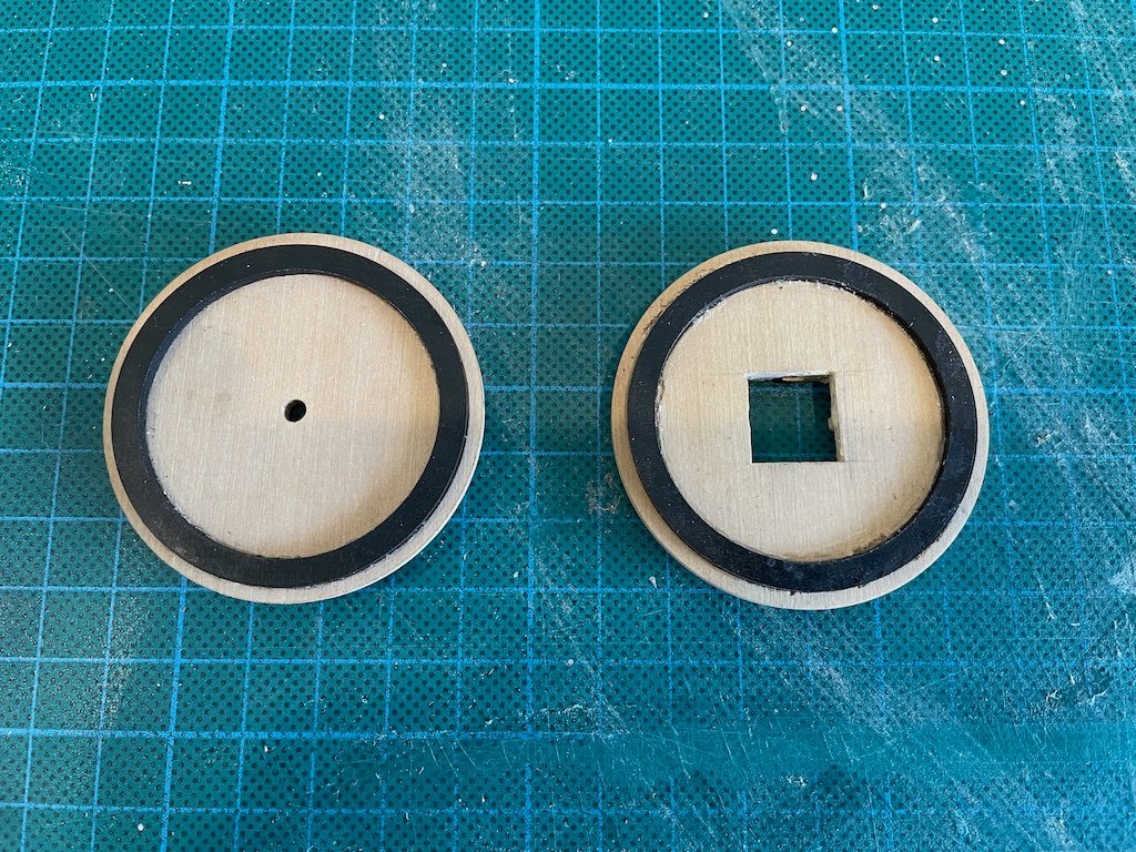
And here are the drumheads after sanding the iron rings flush:
And finally, here is the overall state of play to date. No finish has been applied yet.
Some metal work and the capstan bars are all that remain…
-
Kurt - just wondering when this workshop video will be available on the NRG website as a month has now passed and it’s still not there?
-
-
-
Very nice work so far Rick. Best wishes for your surgery and hoping for a speedy recovery for you.
- Ryland Craze and bruce d
-
2
-
The Drumhead Assembly (P/N 200)
From the instructions, the drumhead is made up of six major pieces: two upper and two lower drumhead halves, an iron ring and the cap, along with several miscellaneous bolts and fittings. I decided that I would make each drumhead as a single piece rather than two halves glued together.
Upper and Lower Drumheads (P/N 18 & 19)
Toni’s instructions indicate that the Drumheads are each made up of two semicircular pieces of wood cut with a jeweller’s or scroll saw and glued together. I’m not sure why Toni took this approach, but assume it was because she didn’t have stock of sufficient width to cut them from one piece. If you’re reading this Toni, you may care to comment. As I had some stock that was wide enough, I decided to make each of these as single pieces.
Toni then goes on to describe the milling process by gluing the two halves together temporarily, and then gluing these to a scrap of wood that is used to hold the parts in the vice on the mill. I was concerned about accurately centering the held parts on the mill, particularly with the amount of de-bonding, re-gluing and re-mounting to the mill.
I thought long and hard about this and have come up with my own solution to the problem. It may not be the best solution, but we’ll see whether it is successful…
To address the centering issue, I thought this would be much easier to achieve if the parts were mounted in a lathe chuck mounted on the rotary table on the mill. That meant that the scrap wood block holding the parts would need to be cyclindrical and held in the 3-jaw chuck instead of square held in the 4-jaw chuck. I don’t own an independent 4-jaw chuck and have more confidence in repeatability from the 3-jaw chuck.
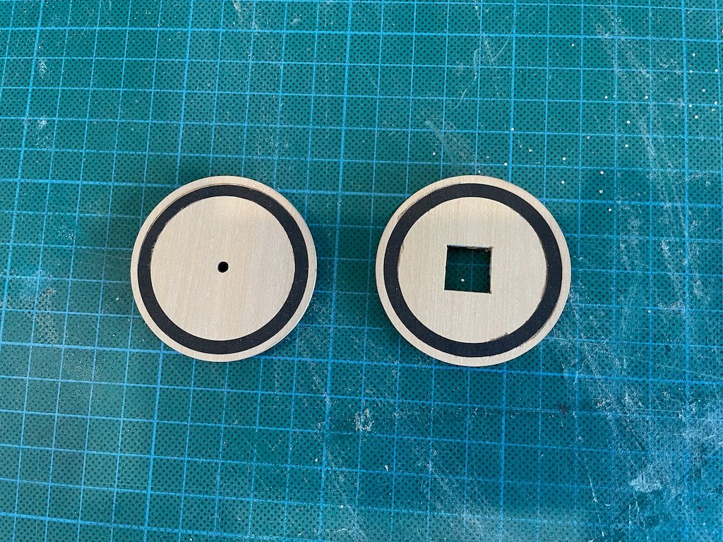
The next consideration was how to easily register the center of the work on the mill, and also with each other when re-gluing. As the lower drumhead will have a large-ish square hole milled in it eventually, and the upper drumhead will receive a cap, I decided that if I drilled a 1/8 hole through all the parts, this would solve both of these problems. So far, so good – in theory…
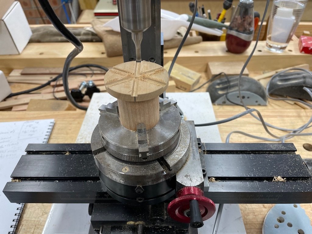
Off I went then. I found a nice block of cherry in my scrap pile and cut this down to rough square on the big table saw. I then found the centre and marked a circle of about the size I thought looked good for a holding piece. I cut close to this line on the bandsaw and then mounted it between centres on the lathe and turned it to final diameter – a relatively quick exercise. I faced the ends square and this part was ready to go.
I then cut the two blanks for the drumheads from 1/4" Box sheet on the Byrnes saw. I made these as close to square as I could get. I marked the centres and drew a circle on each as a guide to the final diameter. I then spot glued these together. Once these were dry, I carefully spot-glued these to my holding cylinder, and once it was dry I went back to the bandsaw to rough cut the drumhead circle. My plan was to then return the glued up assembly to the lathe and turn down the final diameter of the drumhead.
Here is the assembly on the lathe:
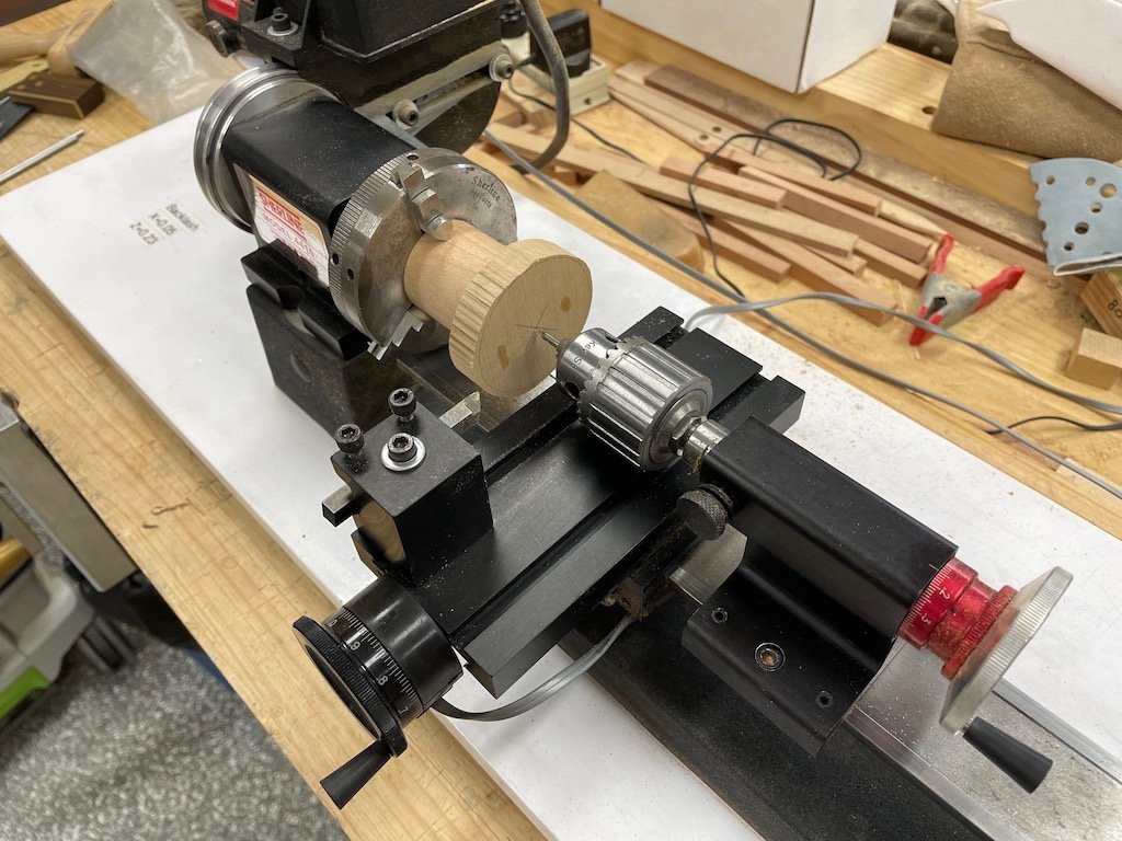
It was about now that I realised that the diameter of the drumhead was too large for the lathe – doh!
While I had it all set up on the lathe, I centre-drilled a 1/8” diameter hole, then followed up with a regular 1/8” drill bit and drilled all the way through all of the pieces, and finally followed up with a 1/8” reamer. The purpose of this was to allow me to use a 1/8” rod to align the pieces when de-bonding/re-gluing, and also as a registration when mounting on the mill.
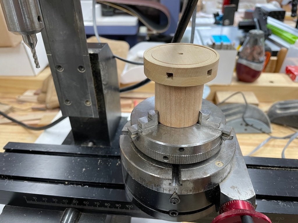
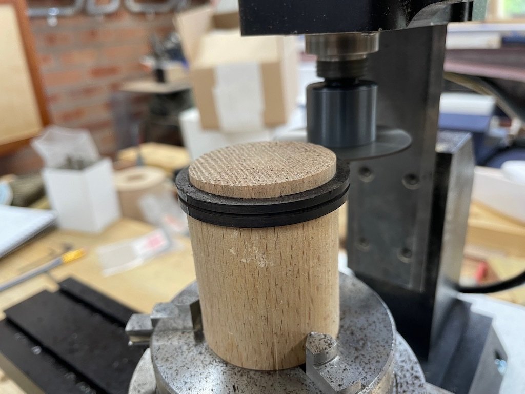
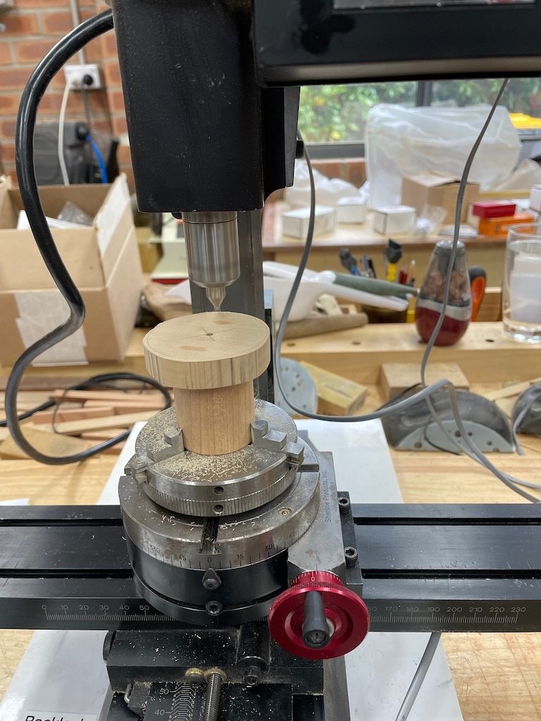
Speaking of the mill, as I could not turn my final diameter on the lathe, I transferred the assembly to the rotary table on the mill and used a 1/8” end mill registered in my locating hole to centre the work on the mill. I was then able to use this set-up to complete turning the final diameter on the drumheads by offsetting the cutter to the required radius (gotta love the digital read out for this job!). Here is the set-up just before commencement of milling.
The milling went well, and I was then ready to cut the rebate for the iron ring. Calculating the width of this from the drawings worked out at 9/64”. My choice of end mills does not include a 9/64” bit, so I had a choice of either 1/8” (8/64) or 5/32” (10/64). After some deliberation, I opted for the larger size on the basis that it might make subsequent fabrication of the “iron” ring easier (perhaps slightly less prone to breakage if made from wood).
That process went well – very similar to turning the final diameter, only a different offset and cutting to a final depth of 0.5mm (slightly deeper than the 0.4mm (1/64”) called for in the drawings). I forgot to take a picture at this stage as I had just received a weather alert for thunderstorms and large hail stones – I had to cease play and put all the tools away so that I could get the cars in the garage before the hail arrived.
The parts are now soaking in an isopropyl alcohol bath prior to separating and regluing to mill the rebate in the other drumhead.
- Glen McGuire, usedtosail, BobG and 4 others
-
7
-
Nice start Rick. This is a great and fun little project. Just remember to take your time, particularly with the planking. Chuck has done what he can to make it easier for us, but it still needs careful attention as you build.
-
Nice job on the Capstan Step Eric - very clean joints. Re the Capstan spindle, I did exactly what you are contemplating and drilled a hole with a standard sized drill bit (5/8” for me, but I’m in a different scale to you). You are absolutely correct that it won’t be seen, so make life easier for yourself where you can.
-
Well done Eric! Some very neat looking joints.
On your last point re matching mortices, it is better to mark both pieces at once. If you hold them together in a vice, with the ends flush, it should be a relatively easy matter to scribe across both pieces. Even if you only make a small knife mark with the tip of the knife in each, you can then complete the layout line with the pieces separated and proceed as you have described. This guarantees alignment without having to rely on your accuracy using a measuring device. My mantra is to never use a ruler/tape measure when I can use a referential measurement like this. Again, this is full-size practice in furniture making.
- mbp521, usedtosail, dvm27 and 3 others
-
6
-
After some minor distractions over the Christmas/New Year week, the build continues.
The Chocks (P/N 030 and 031)
There are two sizes of chocks, with the lower one being thicker than the upper, and the angles of insertion being slightly different. They are essentially a wedge shape when viewed from above, but their sides are also tapered to match the notches cut into the whelps. To simplify construction, I drew up a plan for each in CAD using the dimensions from Toni’s drawings and then duplicated each of these to provide a strip of five templates for each of the upper and lower chocks.
The templates were printed onto sticky label paper and attached to the relevant stock size. The stock was then taken to the Byrnes saw and ripped to a width that would leave plenty of extra length on the chocks for fitting, and then the individual chocks were cross-cut using the angled mitre gauge.
The Byrnes disc sander was then used with the table tilted to an appropriate angle (about 30-deg) to trim the sides to a loose fit. The table was then returned to its 90-deg setting and the inner ends slowly sanded away until the chock was a tight fit. Each chock was marked with its location and the barrel also marked accordingly. The chocks were then glued in their respective locations and left overnight. Once dry, the excess material was removed firstly at the Byrnes disc sander and then with files and sandpaper to achieve the final shape. The concave face on the lower chocks was achieved by firstly making a rough shape using the oscillating spindle sander, and then refining with a contoured sanding block.
Finally, the whole assembly was remounted in the 3-jaw chuck on the rotary table on the mill and the bolt holes were drilled in the chocks. I opted to drill these at 0.7mm diameter to accept some 40lb monofilament for the bolts. This is somewhat thinner than specified but looks about right to my eye.
I got so focused on the process, that I forgot to take any progress pictures. Here is the completed Capstan Body.
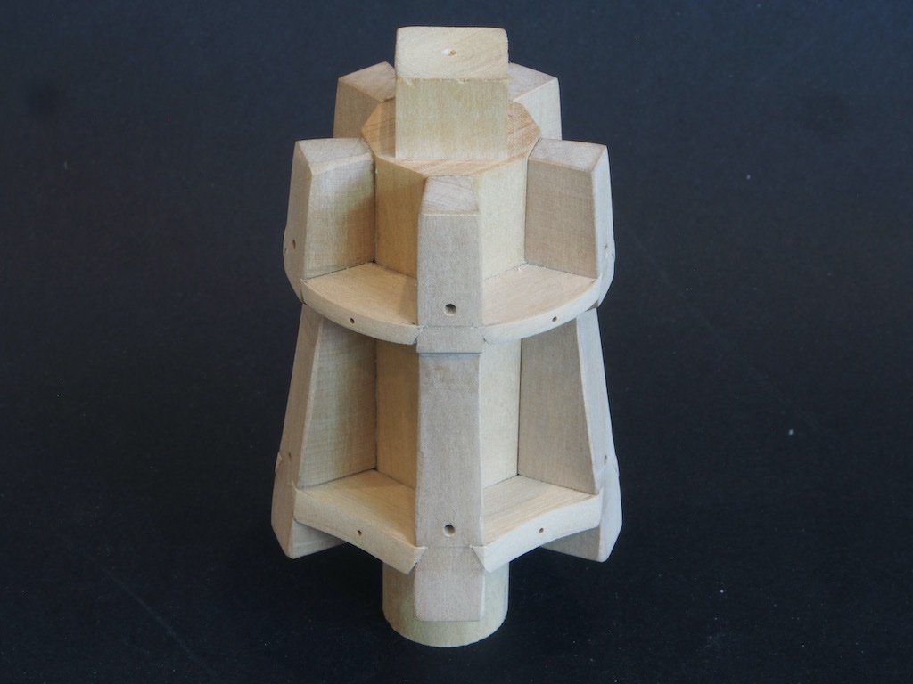
Next up, the part I’ve been dreading – the Drum Head Assembly….
-
Further to Kurt’s excellent advice, it looks to me from the photos that you used the digital calliper and a pencil to mark both edges of the mortice, which will inevitably lead to a loose fit. Use calliper and pencil to mark the rough position of one edge, then use a knife to mark the actual cut line (notice how much thinner the knife line is compared to a pencil line). Then use the carling itself, held in place against the knife line with a small square and mark the second edge, again with a knife. If you use the knife to get really tight against the carling, or perhaps even just under the edge of it, you will end up with a tight joint. The knife lines will provide you with a good reference line to make your saw cuts with a razor saw prior to chiselling out the waste. As Kurt has said, this is how furniture makers do it.
-
Nice progress on the planking Andy.
-
Thank you very much Mark, Kevin, Bob, Gary and Patrick for your kind words, and to all of the “likes” as well.
The model has grown further on the Admiral, who has now requested (nay, ordered) that it take up permanent residency in its “temporary” home in the dining room. Although it has felt at times that the model fought me every step of the way, to have this reaction to the end result instead of just “tolerance” makes it that much more worthwhile. 😊
I’ll be having a case made for it in a week or so when businesses start back up after the Xmas break.
-
-
Hey guys,
Can anyone (other than Richard, who has spent enough time on this already!) answer this for me please?
When I play the file within Dropbox, it is the edited version that runs for approximately one hour, however if I download the file, it downloads as the unedited 4 hr 40 min version. Any clues as to why this is so and/or how to download the shorter, edited version? (I'm using a Mac, in case that makes a difference).
BTW, thanks to those who suggested using VLC - that fixed the sound issue I was having.
-
Hi Richard,
Thanks so much for doing this. I just followed your link and it appears that you've put an edited version up in Dropbox that runs for about one hour. However, when I downloaded it from drop box, it seems to download the full 4hr 40min version. Any idea why this is so? (I'm not all that familiar with using Dropbox, so it could well be "operator error").
Also just discovered that with the long version that downloads, there is no sound at all.......


NRG Capstan Project by gjdale (Grant) - FINISHED - Scale 1:16
in - Build logs for subjects built 1751 - 1800
Posted
Thank you both B.E. And Mark. I continue to follow your own excellent work with great interest.