


gjdale
-
Posts
4,825 -
Joined
-
Last visited
Content Type
Profiles
Forums
Gallery
Events
Posts posted by gjdale
-
-
That’s a very cool base Glen!
-
-
Glad to hear that you escaped without serious injury. Table saws always scare the c**p out of me, which is why I invested in a Sawstop Table Saw. Doesn’t replace the need for vigilance with safety, but does prevent those serious injuries.
- druxey, reklein, Wintergreen and 5 others
-
 8
8
-
-
11 hours ago, Cathead said:
I don't have a lot of experience with fine woodworking, being more of a large-scale builder (I've built a number of outbuildings on our farm and rough furniture, but not anything with precise small joinery like jewelry boxes). So this will be a good way for me to develop finer-scale skills, including chisel work
At the risk of “teaching grandma to suck eggs”, to get accurate joints, mark your cutting lines with a knife rather than a pencil and use referential measurement whenever you can (eg mark the first cut line for a mortice from the given measurement from the end of the piece, then mark the second cut line by placing your tenon piece against the first cut line and using it to define the width for the second cut line). Hope that makes sense.
-
1 hour ago, Cathead said:
I followed @gjdale in making a spreadsheet for converting the plan measurements into scale. Although he made his available to others, I stubbornly made my own so it'd be just the way I wanted it. I set it up to convert full-size measurements into both fractional and decimal inches, since I think more clearly in fractional but decimal will be easier to measure in at small dimensions. Metric would have been sensible, too, and I'm used to it as a scientist, but I still do most of my woodworking and building in fractional inches so I went with what's easier for me, cognitively speaking.
Hey Eric,
A couple of things I found in using my spreadsheet:
In addition to having a table of the stock dimensions, I have found it useful to create an extra box to enter specific or one-off measurements and have the computer spit back out the appropriate scale dimensions in fractional inches, thousandths, and metric. I could then write these onto Toni's drawings as needed.
Like you, I am "bi-lingual" when it comes to imperial/metric measurements. Although I use metric for the lathe and mill because that is how they are geared/calibrated, I have found it much easier to stick with imperial units for everything else as the conversion to scale size seems to be generally a little "cleaner" to use (eg an inch ruler might have 32nds marked on it, but a metric one doesn't have x.3mm etc).
The digital caliper with both fractional and decimal inches (as well as mm) is your friend!
For accurate mortises, a knife line and a very sharp chisel are the key to success (as I'm sure you know from your other woodworking).
-
-
Well done on your victory over the PE Mark, she’s looking great!
- Nirvana and Old Collingwood
-
2
-
Floyd,
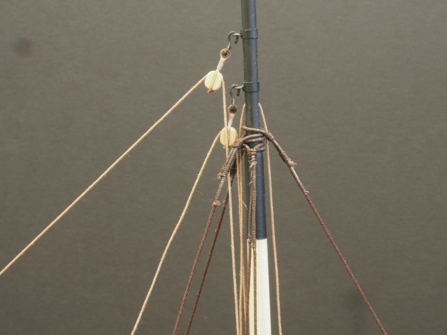
If you take a look at post #87 in my log you will see a photo of the top of the mast and it shows quite clearly where the line has been served, and then seized to form the loop. I’ve copied that photo for you below, but please feel free to delete if it is cluttering up your log.
-
Dave,
A little research on your subject ship should tell you the actual sizes of the various blocks and ropes used. The Anatomy of a Ship series is often a good start. There are various other sources that can provide guidance on typical rigging sizes used for your size of ship for its particular time period. Once you have that information, just create a spreadsheet to convert the actual size to your chosen scale in the measurement units of your choice.
-
Floyd,
To stat and finish serving, I use a sewing needle to pass the serving material through the line being served. A touch of diluted white glue on completion just for added security does the trick for me.
Not sure I understand the second part of your question.
-
Thanks Glen,
Apart from three requisitioned by the Admiral, all of the other reindeer were given away to family and friends, where they all received warm welcomes into their new homes.
- Glen McGuire and mtaylor
-
1
-
 1
1
-
Thanks for the kind comments Ben and Rusty, and for all of the likes. Life seems to have gotten in the way lately, so progress has been slow.
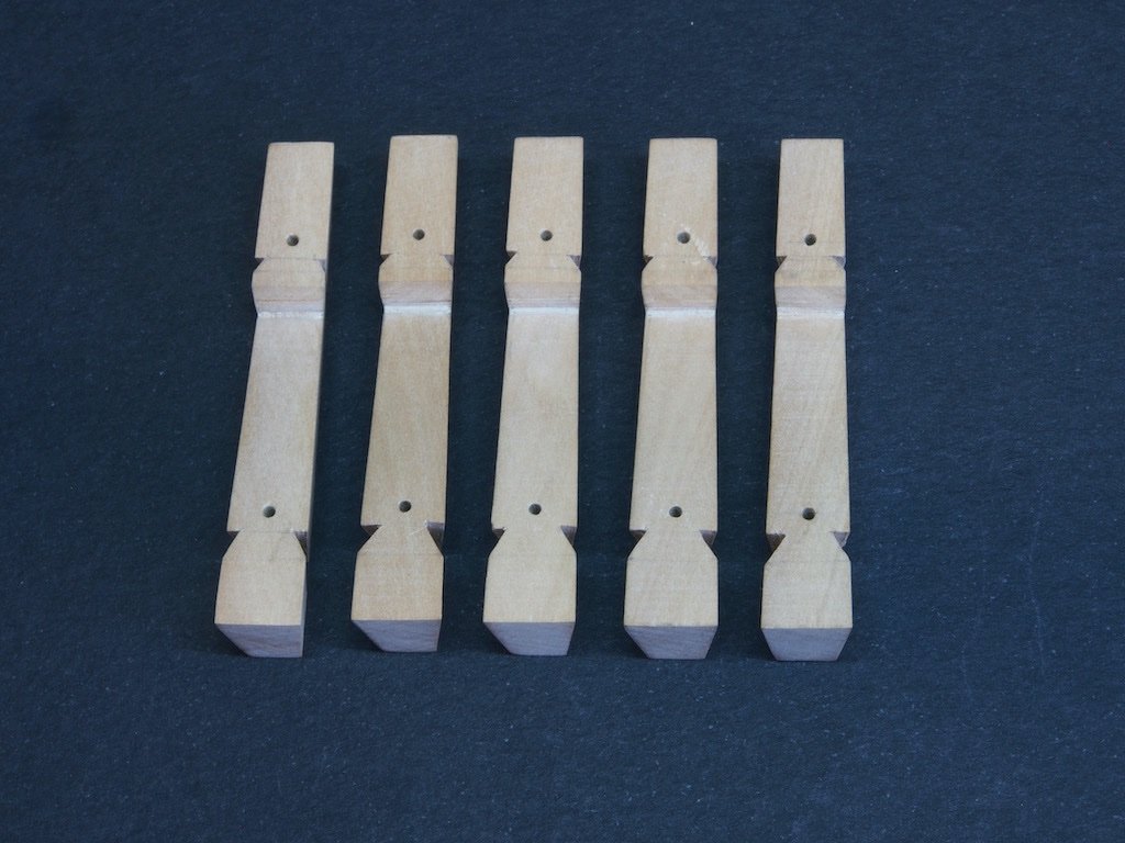
The Whelps (P/N 029)
Five Whelps are required and the particular challenge in making these is that they are tapered both top to bottom and rear to front. The first step was to cut some blanks and then glue them up into a sandwich with the basic profile outline on one face.
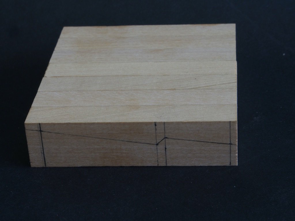
Toni’s advice in the instructions was to make a couple of spares, so initially I glued up a set of seven blanks. Unfortunately, when it came to milling the sandwich, I found that it was too wide for the mill travel, so I had to unglue them and re-glue with just five in the sandwich.
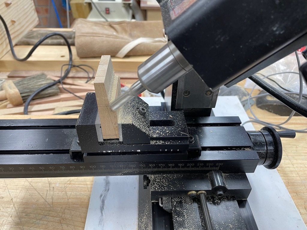
The basic profile was then cut on the mill by angling the milling head as shown by Toni in the instructions. Here is my set-up halfway through the milling process:
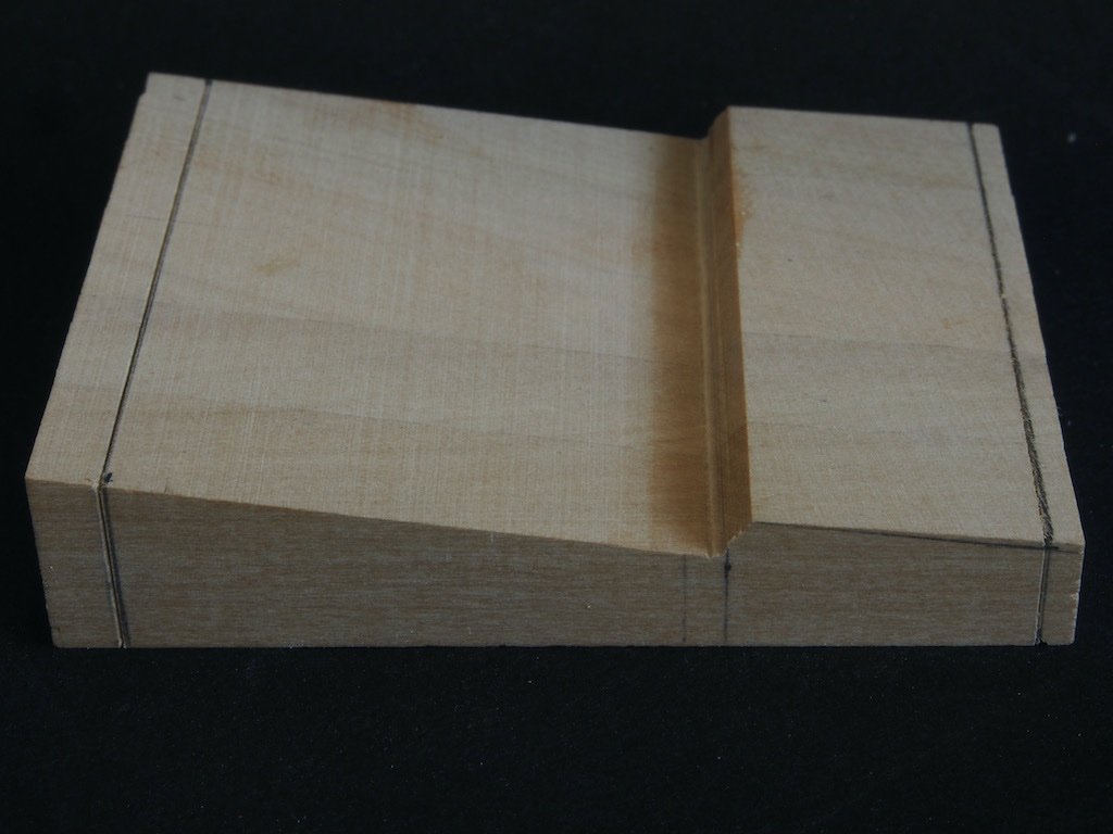
And here is the end result. Note that the blanks were left slightly long to allow for any chip-out during milling.
The blank was then taken to the Byrnes saw and trimmed to length prior to soaking in an IPA bath to separate the individual pieces.
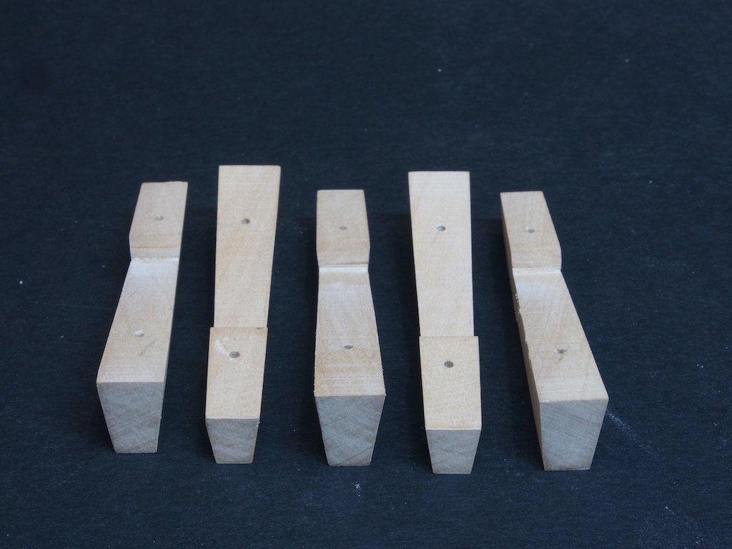
Once separated, holes were drilled for the bolts and the individual pieces carefully marked out for the tapers. The top to bottom taper was tackled first, and is relatively simple to achieve using the Byrnes disc sander to freehand sand to the marked lines. The rear to front taper was a little trickier. After carefully marking out, the angle was measured using a protractor and the tilting table of the Byrnes sander set to this angle. With a little care, the correct taper was achieved. Here are the pieces after all tapers had been cut/sanded.
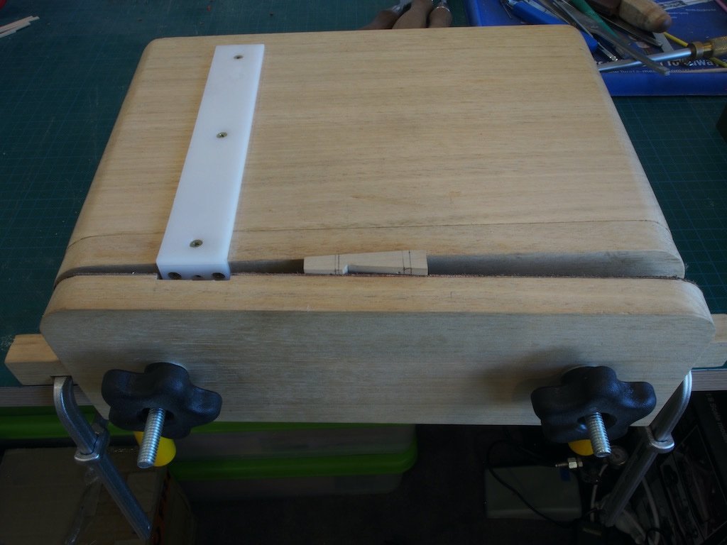
The next challenge was to cut the notches for the Chocks. Like many things in woodworking (or metal working for that matter), the hardest part of the process is working out how to hold the work securely for the operation at hand. Having carefully marked out each piece for the notches, I found that my home-made Moxxon style vise was able to cope with the tapers quite well to hold the work.
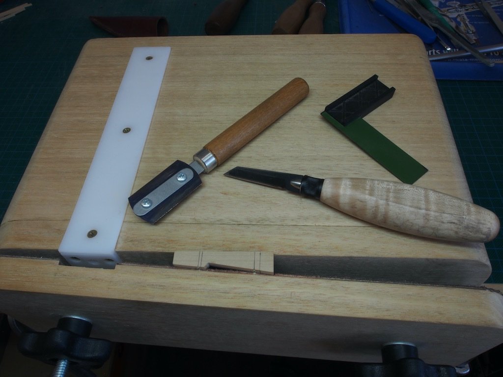
I then used a miniature square and a marking knife to score the vertical cut line. This then provided a handy registration for the razor saw to make the vertical cut.
A freshly sharpened full sized chisel was then used to pare the angled cuts.
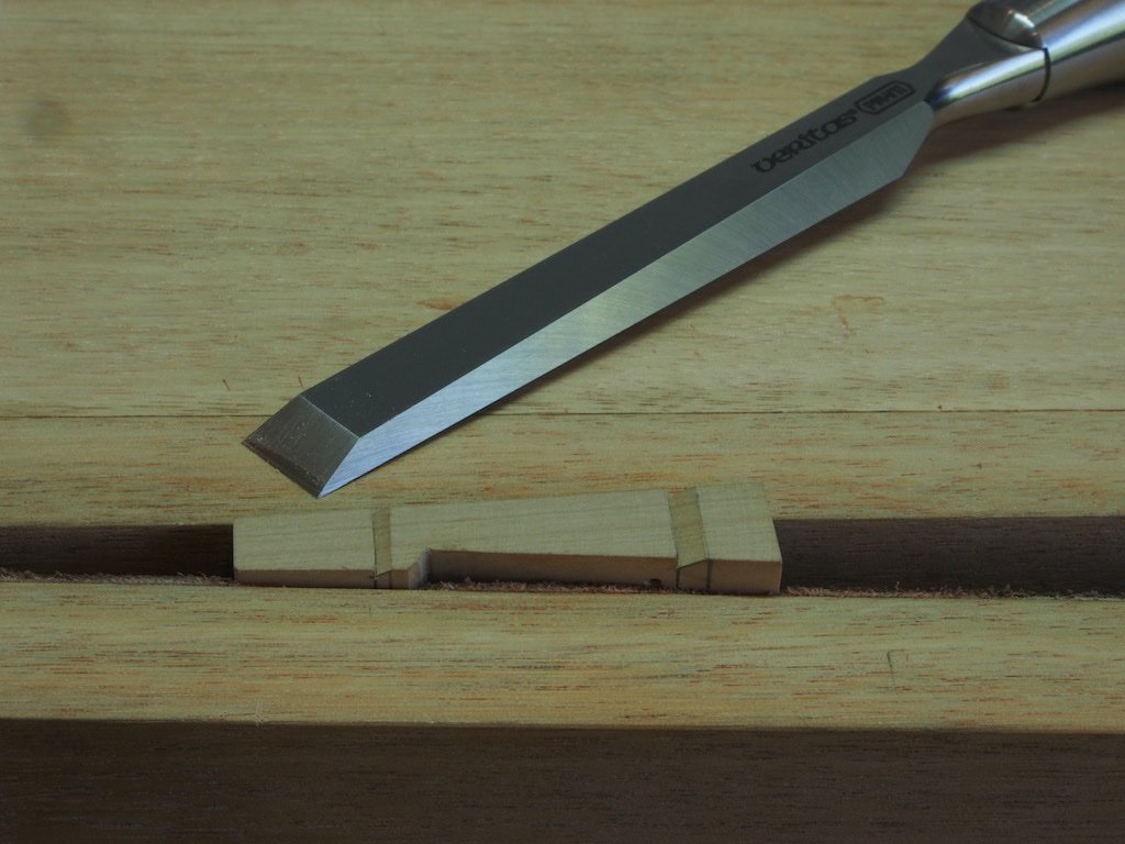
Having worked out how to hold the pieces, the actual cutting of the notches went quite quickly. Here are the completed Whelps.
The Chocks will be next but will probably have to wait a day or two until after the fat man in the red suit has been.
- GrandpaPhil, MEDDO, JpR62 and 5 others
-
8
-
-
Nice trick with the wedge Andrew - thanks for sharing.
-
-
Great job Tom, well done!
-
Good solutions Glen!
- Glen McGuire and mtaylor
-
1
-
1
-
-
FLoyd, I’m not sure what you are referring to here. If you’re talking about seizing of blocks and you are seeing gaps they are unintentional. If you are talking about securing the tail end of a shroud or stay, then there are two seizings with a space between them. I can’t remember how many “wraps” I used for each - just until it looked about right.
-
Floyd,
Thanks for the kind comment on my seizings. There are many ways to do the seizing. The way I do them may not necessarily be correct, but they seem to look okay. I generally just use a simple series of overhand knots tied on alternate sides of the seizing. I start furthest from the block and work back towards the block, so that the seizing closes up the gap. I then put a dab of diluted PVA on the entire seizing and trim the ends once dry.
-
Just stunning Gary. As others have noted, it is only when one sees the last photo with your glasses next to it, that the scale can be truly appreciated. Bravo Sir!
-
Ah - that's good then - a whole 1/16" to spare. What could possibly go wrong? 😁
I'm still a couple of weeks away from starting my Amati Hannah - gotta get this Capstan Project finished first (thanks for looking in).
-
Glen, I might be pointing out the obvious here, but.......
Your bottle neck opening is 11/16".
Your scale model breadth is 3/4" (ie 12/16")
Do we have a problem?
- mtaylor, Ian_Grant and Landlubber Mike
-
2
-
 1
1


1869 Allerton Steam Pumper by gjdale - Model Trailways - Scale 1:12 - Finished
in Non-ship/categorised builds
Posted
Final Completion
After a frustrating couple of months waiting for parts, the model is finally completed. I managed to source locally (relatively) some clear plastic rod of the correct diameter to complete the boiler gauge sight glass.
I also took some time to write a constructive email to Model Expo with a detailed list of the errors in parts, and in the instructions, that I had encountered and asked only for replacements for the hoses and three bolts. I figured that since Model Expo claim a free parts replacement service this shouldn’t be too hard, especially since I had gone to the trouble of clearly identifying the issues for them.
Turned out not to be quite that simple. It was only after I involved the company owner (Marc Mosko) that I even got a response to my emails – the first email went completely unanswered for a month before I wrote a second time. Then a person in the parts department took it upon themselves to make it more difficult than it needed to be by insisting that I complete their online form for replacement parts, even though I had already provided every single piece of information on that form and more. That same person also told me that I would receive exactly the same parts as originally provided (never mind that the parts were incorrect). I was not prepared to put up with this nonsense so once again drew Marc Mosko into the conversation. Someone must have received the proverbial kick in the pants because I was then contacted by someone else in the parts department who couldn’t have been more helpful. The only further snag was that because of the cost of postage these days, they decided to include my replacement parts in a shipment to their Australian distributor, who would then forward my parts on to me. I can’t fault them for that – in fact it was a sensible approach. Anyway, the parts finally arrived on 29 Dec (more than two months since my first email) so Model Expo did make good on their promise and I’m grateful for that, even if their customer service is somewhat lacking.
Once I had the hose material in hand, it was a simple matter to cut them to approximate length, dip the ends in CA glue to stop them fraying and while the glue was still wet, insert the end of a paintbrush to open the ends and stop them sticking together. Once the CA had dried, the hose ends were trimmed to final length and the hose connectors inserted and glued in place. The hoses were then painted with a liberal amount of watered down PVA glue (50/50 glue/water mix) and left overnight to dry. This made the hoses relatively stiff but still malleable and able to be formed to some sort of shape prior to installing on the model.
So here at last are some final shots of the completed model. The Stbd side:
A close-up of the Boiler Water Level Sight Gauge:
And the Port side:
Despite its many frustrations, this has been an enjoyable build and I’m well pleased with the final product. More importantly, the Admiral likes it, and it is now on display in a temporary home in the dining room. Now I can get back to finishing my Capstan project.