


gjdale
-
Posts
4,825 -
Joined
-
Last visited
Content Type
Profiles
Forums
Gallery
Events
Posts posted by gjdale
-
-
Glad to hear the painting tip worked out for you. Wish I could take credit for it, but I picked it up from someone else here on the forum. Your paint job looks excellent.
-
Great to see you back Vivian, and as others have said, congratulations on your marriage. I wish you many happy years together.
- Vivian Galad, mtaylor, CaptainSteve and 3 others
-
 6
6
-
Chris,
You can’t go better than the Byrnes saw and many of us Aussies have the privilege of owning one. You just have to be prepared to pay the exorbitant postage fees, which are beyond Jim’s control. At the time I bought mine, the postage added about 50% to the cost of the saw. Nowadays, you’ll also have to be prepared to pay GST as well....
It hurts, but it’s worth every penny! As the saying goes, “quality is remembered long after price is forgotten”.
- druxey, Cabbie, CaptainSteve and 1 other
-
4
-
-
I look forward to following your progress on this one Kevin.
-
Okay - just made it in time for a front row seat!
-
Looking good David. If you’re worried about paint getting under the edge of your masking tape, try sealing the “wet” edge of the tape with a coat of clear varnish first.
-
Great to see you back at the bench Patrick, with your lovely model. Welcome home!
-
I love the Chris Craft boats. Are you going to make this a working RC model?
-
Outstanding, as always, Rusty. I look forward to following your next project.
-
Looks pretty good to me B.E. and knowing your attention to detail, I suspect you will be dissatisfied if you decide NOT to do the other 11 guns. So best you get back to it!!!😉😄😄😄
- Martin W and Blue Ensign
-
2
-
I have not one, but two Pocher kits in my stash awaiting my attention.........
- Keith Black and mtdoramike
-
2
-
-
While you’re waiting for the Winnie, Bob, maybe a Medway Longboat or a Royal Barge from Chuck would help to fill the time?
- Canute, Old Collingwood, CaptMorgan and 2 others
-
5
-
Congratulations on yet another fine build Bob, despite the best efforts of the kit manufacturer!
Here’s wishing you improved health and greater enjoyment of your modelling in 2019.
- Canute, Martin W, Old Collingwood and 1 other
-
4
-
-
Closing in on the finish line Kevin! Great work so far.
-
Thanks Carl - and Happy New Year to you and yours too.
Thanks Mark for helping with the edit - though I seem to have lost an earlier picture now. I’ll try to reinstate that tomorrow.
Thanks Mark (Ponitachedmark) for the kind comment.
- CaptainSteve, mtaylor, Canute and 2 others
-
5
-
Thanks Carl, and to all of the "likes".
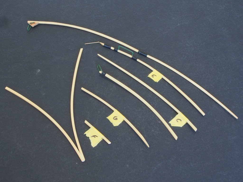
Construction of the wings begins by placing the shaped ribs individually over the wing plan and cutting a variety of lengths and shapes. The photo below shows some of these ready for use:
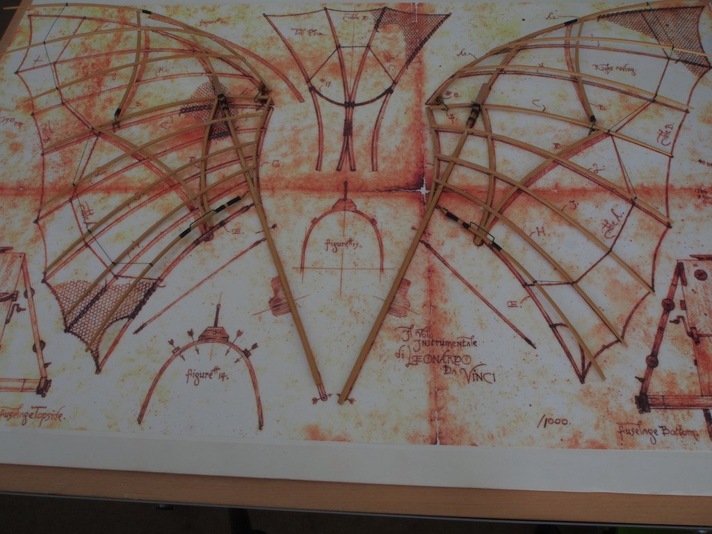
Once all ribs are cut to size/shape, the wings are built up over the wing plan, in alphabetical order. Here is what this phase looks like:
Here is a photo of the wings at this stage, removed from the wing plan:
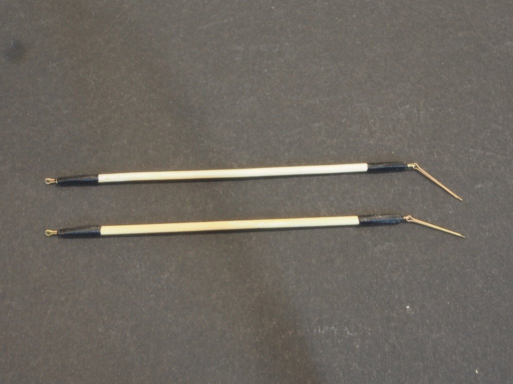
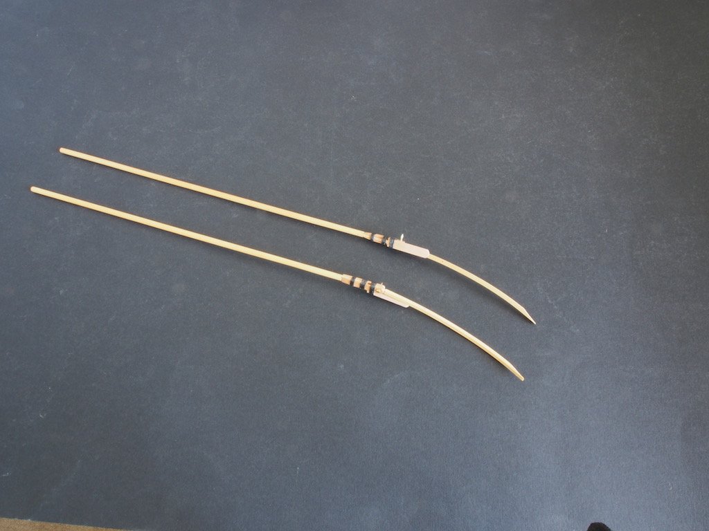
Two wing struts were then made, fitted with hardware and seized with thread – the plans call for them to be slightly different lengths:
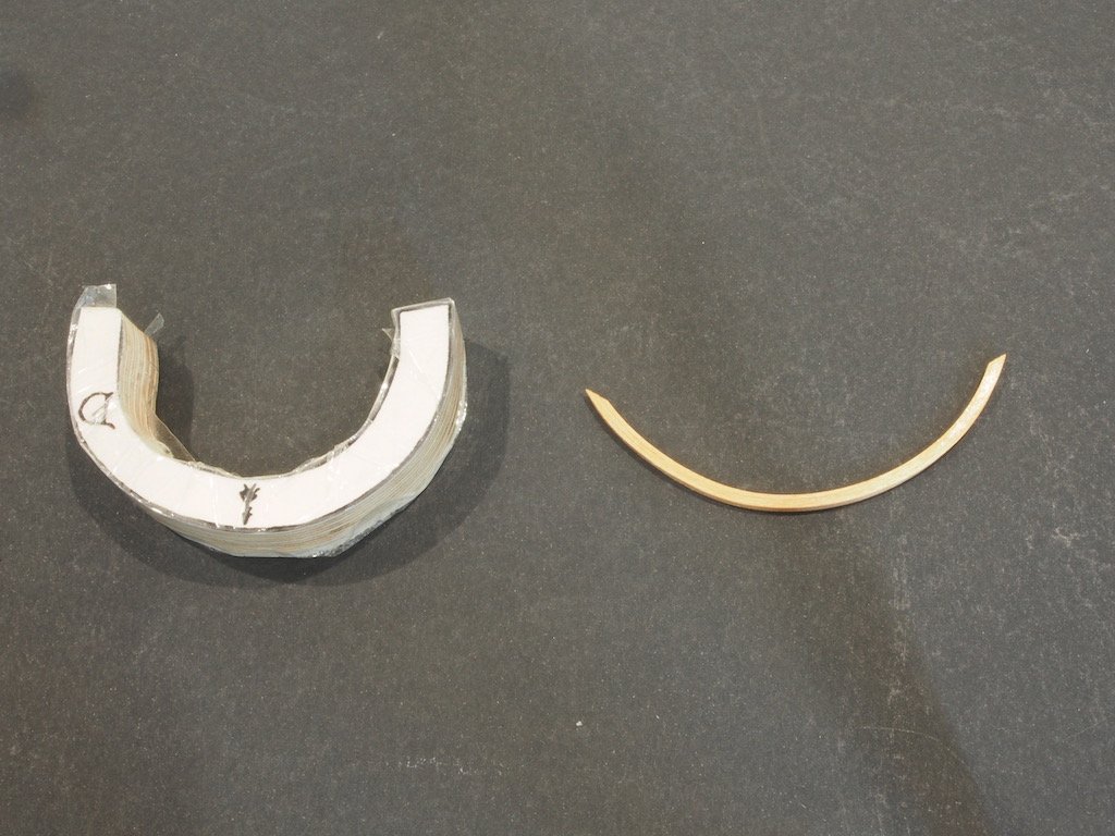
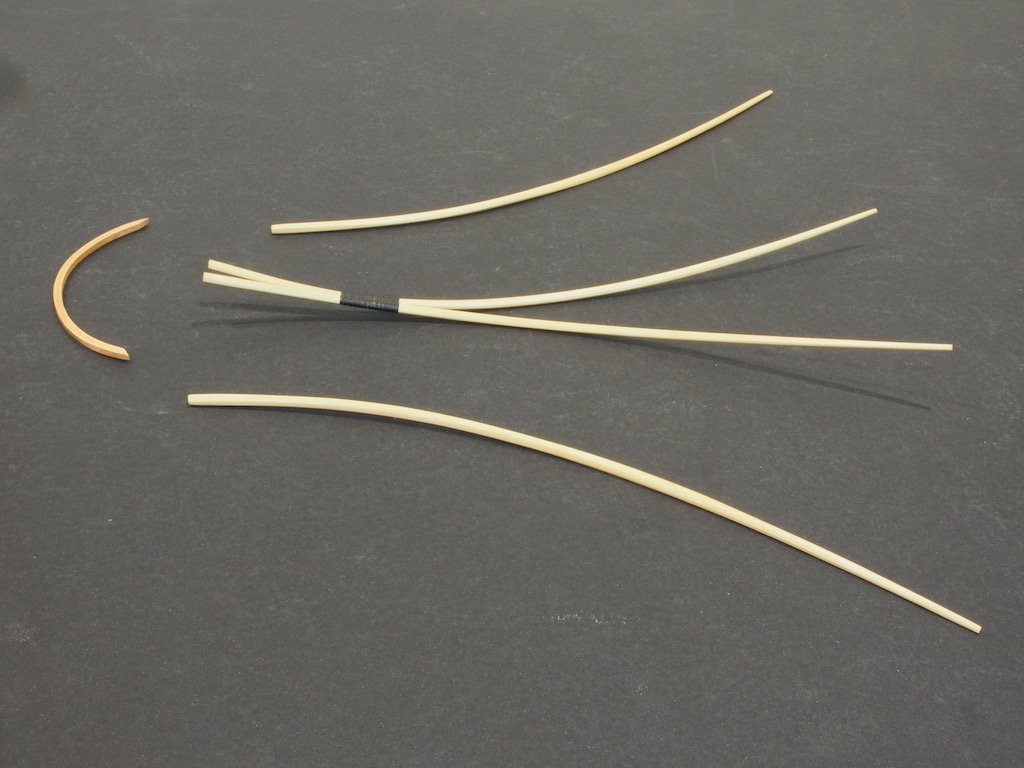
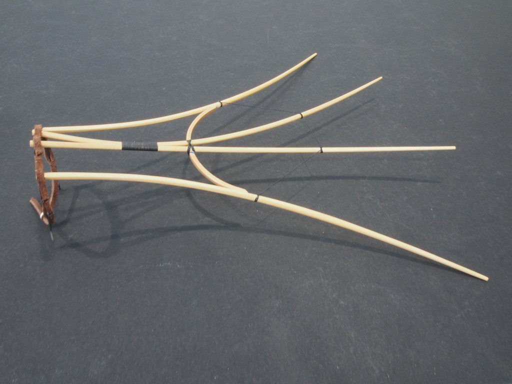
Construction of the tail section begins with creating a curved “shaper” made up by laminating three pieces of 1/8” x 1/32” Cherry around a plywood former created from the supplied template. The “shaper” is then placed over the wing plan and trimmed to final size/shape:
Two of the remaining wing ribs are then glued and seized together such that they curve in three dimensions. Here are all of the tail pieces prior to final assembly:
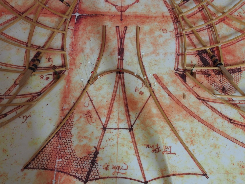
Tail construction then proceeds with the shaper and two outer ribs glued together over the wing plan:
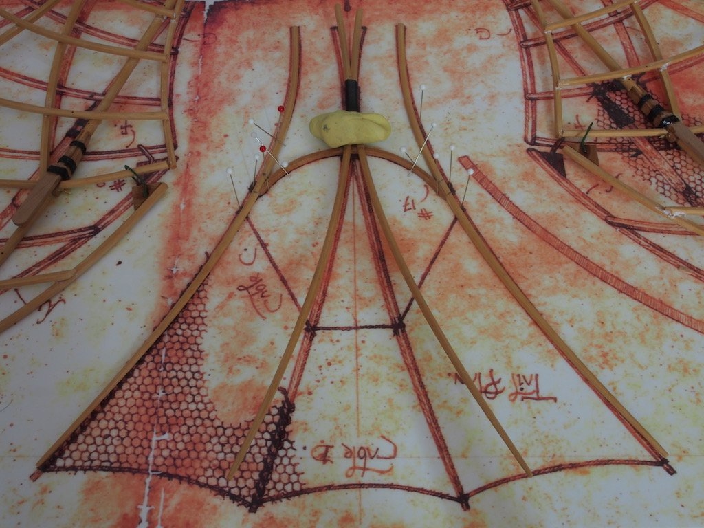
The two inner ribs are then notched on the underside and placed over the shaper. The blob of “yellow tack” is to provide some weight/balance so that the inner ribs set in the correct position:
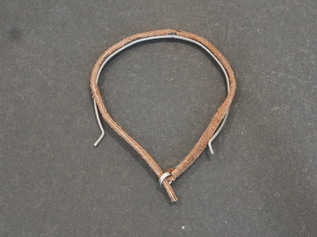
The Tail Mounting Bracket is then made by first bending a piece of (very) stiff wire to shape and then adding a leather strap, which was first cut to shape and fitted with a “buckle” as well as two slits for the wire:
The Tail Mounting Bracket is then attached to the Tail Assembly:
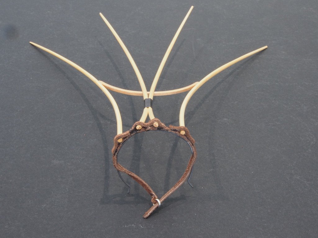
Finally, some cable (thick thread) was added in accordance with the Wing Plan. Here is the final Tail Assembly:
The next step will be to cover both wings and tail assembly with mesh, followed by final assembly of all parts to the fuselage. The finish line approaches…
- GrandpaPhil, Dan Vadas, Canute and 12 others
-
15
-
Hey Slog,
Nice to see an update on your lovely model. I understand fully the inconvenience of work getting in the way of the important stuff! Let’s face it, modelling isn’t a matter of life and death - it’s far more important than that!!!
- Captain Slog, mtaylor, Canute and 1 other
-
4
-
-
5 hours ago, vossiewulf said:
BTW do you know if brass blackener works on copper?
For blackening copper, you need to use Liver of Sulfur. Readily available online. I use the gel form. A little goes a long way. The best thing about it is that you can use it ‘in situ’ and just rinse off the surrounding wood with water if there is any overspill. Much easier to use than brass blackening solutions too! Ed Tosti uses it extensively on his builds (Naiad, and Young America) - he actually uses copper where he can instead of brass.
-
Glad to hear the good news John, and looking forward to further resumption of play.
- Piet, mtaylor and popeye the sailor
-
3
-
It's been a long time between drinks for this log! The usual "life got in the way" excuse applies - mainly work-related - but I have managed to re-commence work on this project in the last couple of weeks - spurred on by receipt of my Medway Longboat kit from Chuck!😉
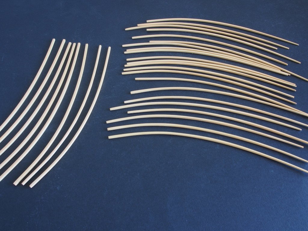
The somewhat tedious process of shaping all of the spars was the next step.
The two spars of shape ‘B’ were sanded square and set aside. Of the 30 spars of shape ‘A’, eight were sanded square and set aside. The remaining 22 were tapered square from two thirds of the way back to the end of each rib. After tapering square, these 22 along with two that were not tapered, were all shaped octagonal. I found the easiest way to do this was using a very small hand plane. All the spars were then given a finish coating of Shellac followed by furniture wax. Here are the resulting spars, although the photo does not really show the shaping terribly well.
It was then on to the main wing spar shafts. Although the kit provided some 3/16” dowel for these, I used some 1/4" square boxwood stock to make these. After cutting to length, I started by drilling the holes as indicated in the plans while the stock was still square. I then used an approximation of the 7/10/7 rule to draw some layout lines for shaping to octagonal, for which I again used a small hand plane. The spars were then chucked in a hand drill and sanded round to the final thickness of 3/16”. It sounds like a lot of work, but this progressed quite quickly in the end. One end of each main spar was then shaped with a ‘step’ to receive two parts similar to a gaff neck (the part is unnamed in the instructions). These parts, together with the shaped end of the spar shaft, form a housing for the next part called a ‘spring clamp’, into which a wing-tip spar (cut from the spar shape 'B') was inserted. Once all the shaping was complete, the spar shafts received the usual treatment of shellac/furniture wax. I forgot to take any progress photos of this stage.
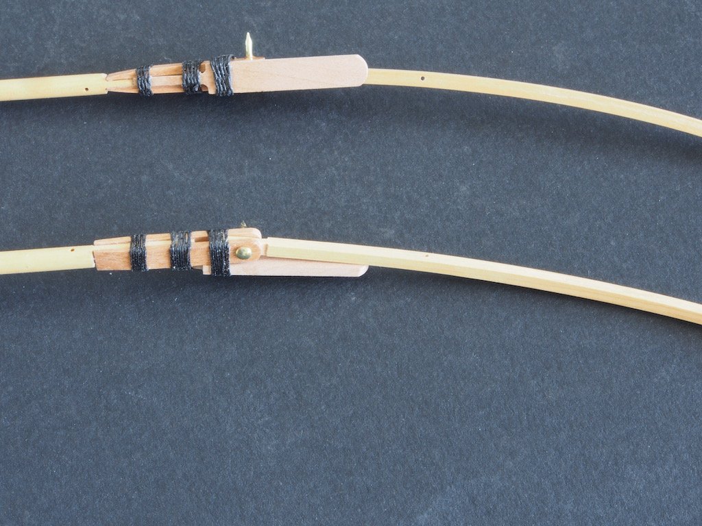
The spring clamps were shaped from 1/4” x 3/32” Cherry stock and fitted to the spar shaft housings using a dab of glue and three ‘seizings’. Here is a photo of the completed main spar shafts, with wing-tip spars inserted.
and a close-up of the spring-clamp arrangement...
All of the shaped spars, together with the main spar shafts, will now be used to construct the wings.
Red Dragon by Vivian Galad - Artesania Latina - 1:60 - modified
in - Kit build logs for subjects built from 1851 - 1900
Posted
By the way Vivian, where are the wedding photos? You know what they say, if there’s no photos it didn’t happen! Just sayin’.........😉😁😁😁