HOLIDAY DONATION DRIVE - SUPPORT MSW - DO YOUR PART TO KEEP THIS GREAT FORUM GOING!
×


Richard44
-
Posts
429 -
Joined
-
Last visited
Content Type
Profiles
Forums
Gallery
Events
Everything posted by Richard44
-
 It's looking really good Eugenio.
 -
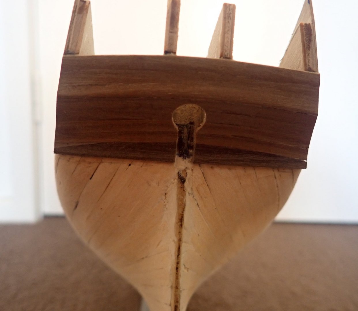
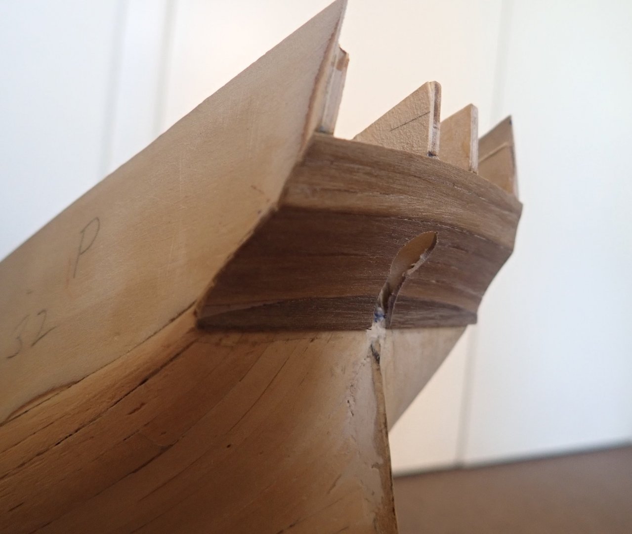
Again, thanks for the comments and the likes. Not much progress this time, in fact it was one step forward and two back at one point. I glued the lower counter (Part 146) in place at the stern, then decided to plank this to reflect the actual ship. The instructions call for the upper counter to be planked (there is no false counter) but they are rather vague, and the only diagram showing the upper counter is in the instruction book, not on the plans, and is not to scale. The rearmost edge of the gunport pattern was not cut especially cleanly which hampered efforts to accurately locate the upper counter. After some head scratching, sanding to clean the edge of the pattern to better match the plans and measurements, both counters were planked, the lower using 1x4mm walnut strip, and the upper using 1x3mm. The instructions actually call for the latter to be 1x4mm as well, but three strips of 3mm fitted neatly. The following day, I looked at what I had done and became more and more unhappy, in particular with the lower counter. The supplied ply counter plus the planking made the whole thing too thick and it was very obvious that the second planking was not going to finish against this neatly. I offered up some 1x4mm strips (the size of the second planks) to the counter, and it looked terrible. So out with the isopropyl alcohol and off with both counters. Two steps back. I should mention here that I have only used PVA glue on the hull, the only CA I have used so far was in constructing the capstan. This time, I just planked the lower counter as well as the upper. The walnut strips, again 1x4mm for the lower and 1x3mm for the upper, were edge bent using Chuck’s method before fitting. A second plank offered up to the counter looked good this time. Both counters will be painted, the lower black, the upper blue. There will also be decorative strips between the second planking/lower counter/upper counter and stern window fascia. That’s it for now. Cheers.
- 104 replies
-
- 5
-

-
- pegasus
- victory models
- (and 2 more)
-
I agree wholeheartedly. BE's log is a constant source of ideas - though all errors are of course mine 😕 Cheers
- 366 replies
-
- 4
-
-
- pegasus
- victory models
- (and 2 more)
-
Nice job on the planking.
-
If it took you as long as it did me to sand the hull, then you had plenty of time to enjoy the plenty of sawdust 😄😄. It's looking good Tim.
-
It all looks really good. If you did half cut from the outside the three bulkhead extensions, you shouldn't need a flush-cutting saw to remove them. A simple twist with pliers and they should snap off quite cleanly. A sanding stick smooths the broken tops, then you finish your deck planking over them.
-
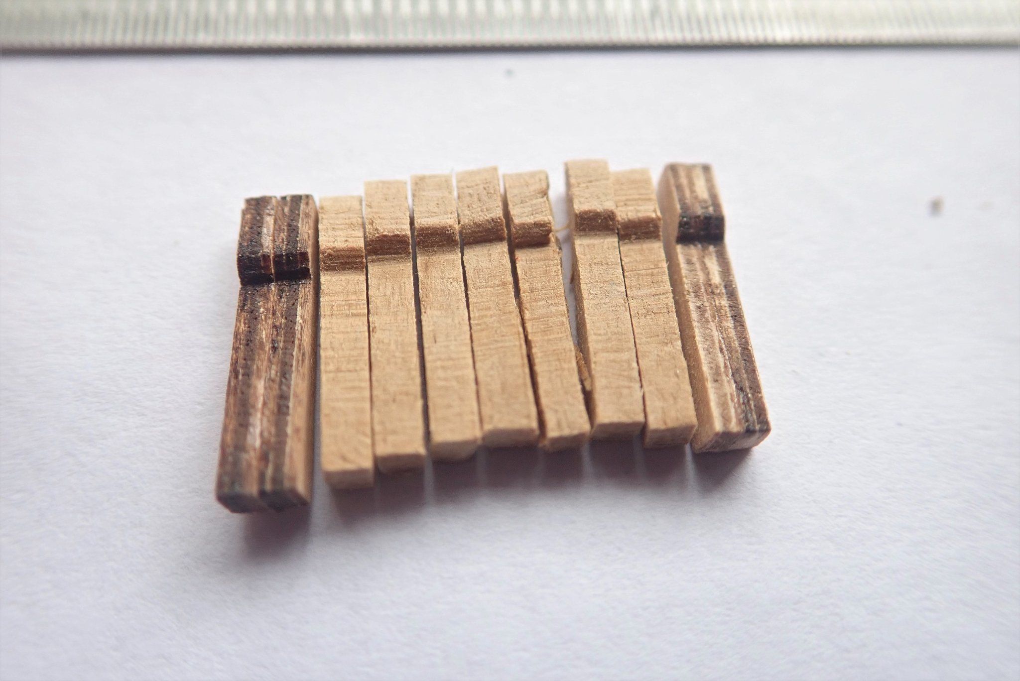
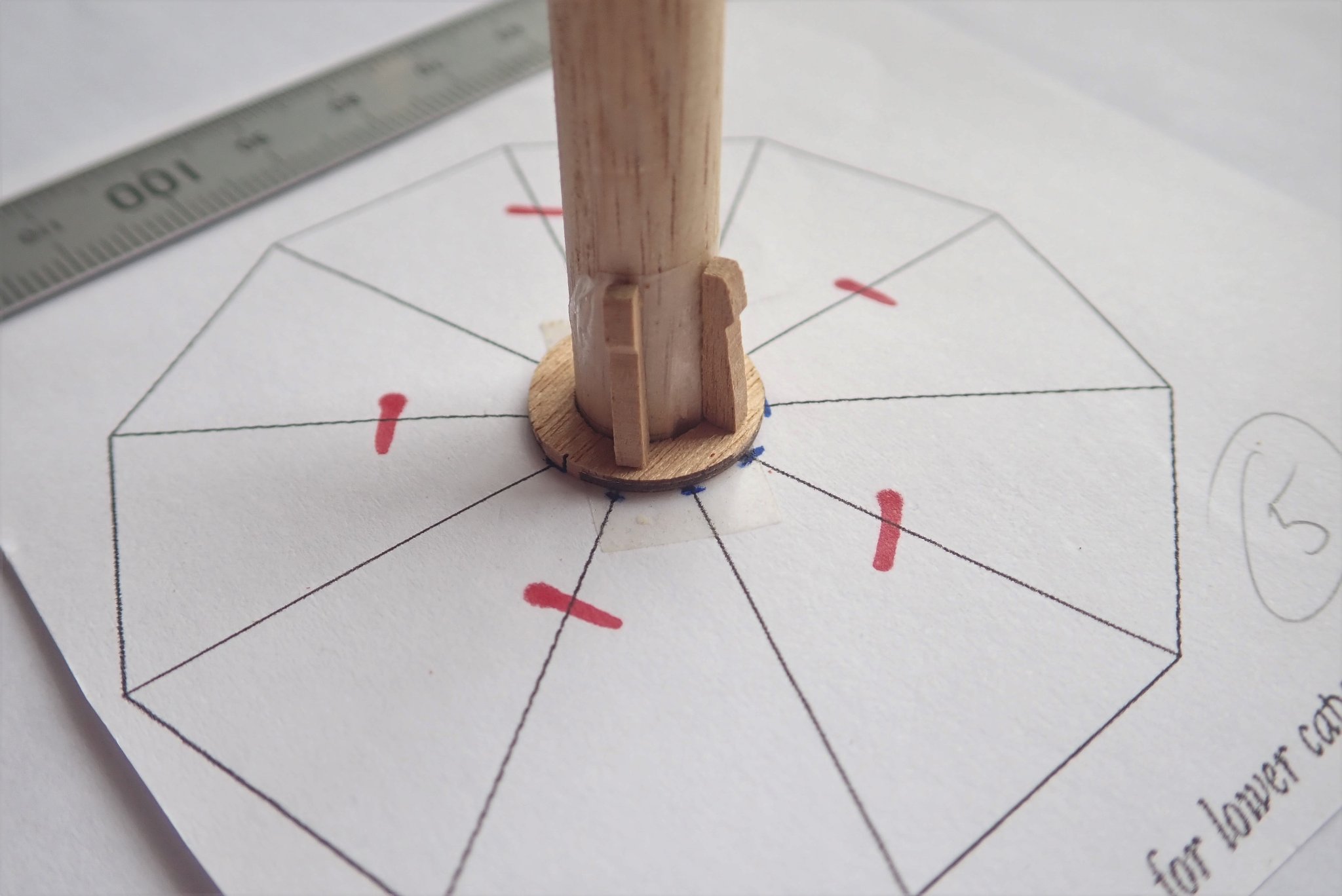
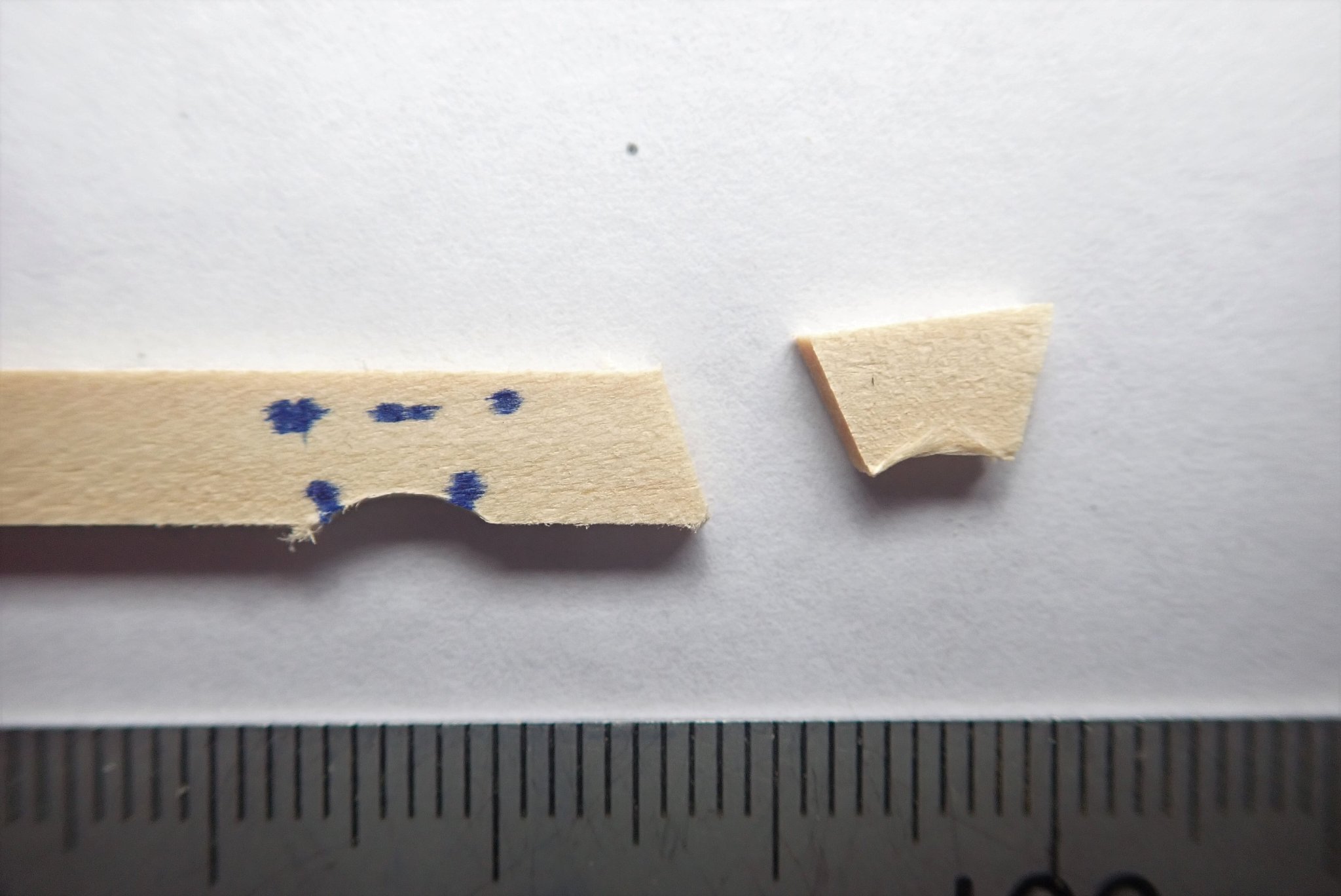
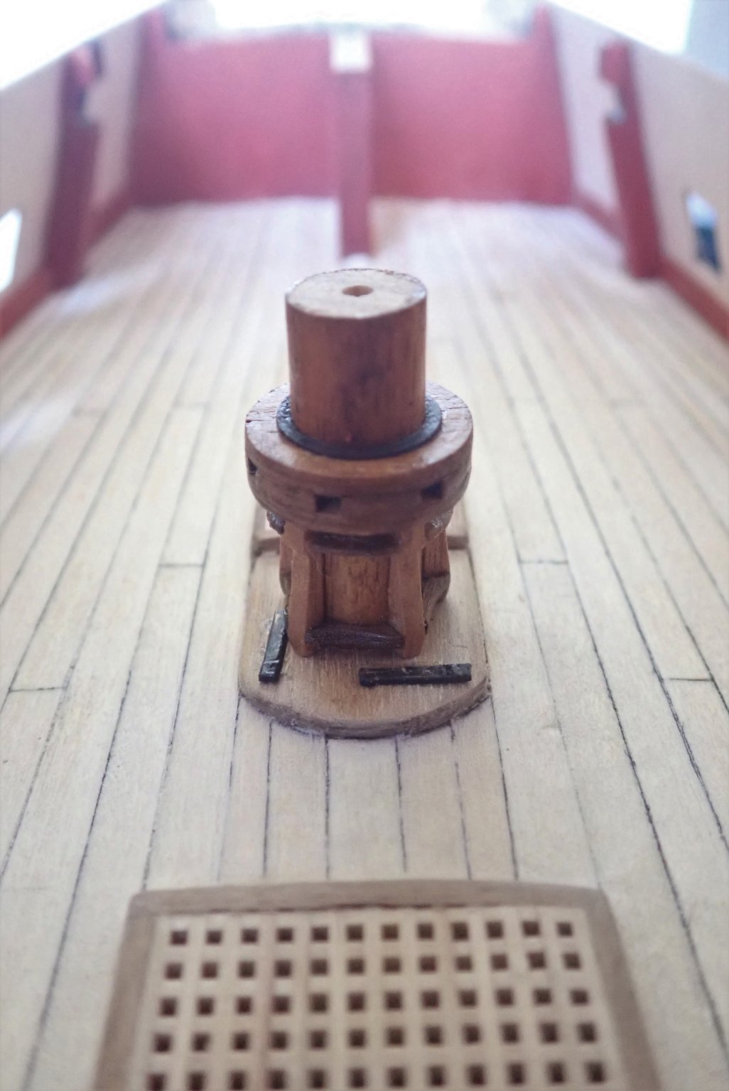
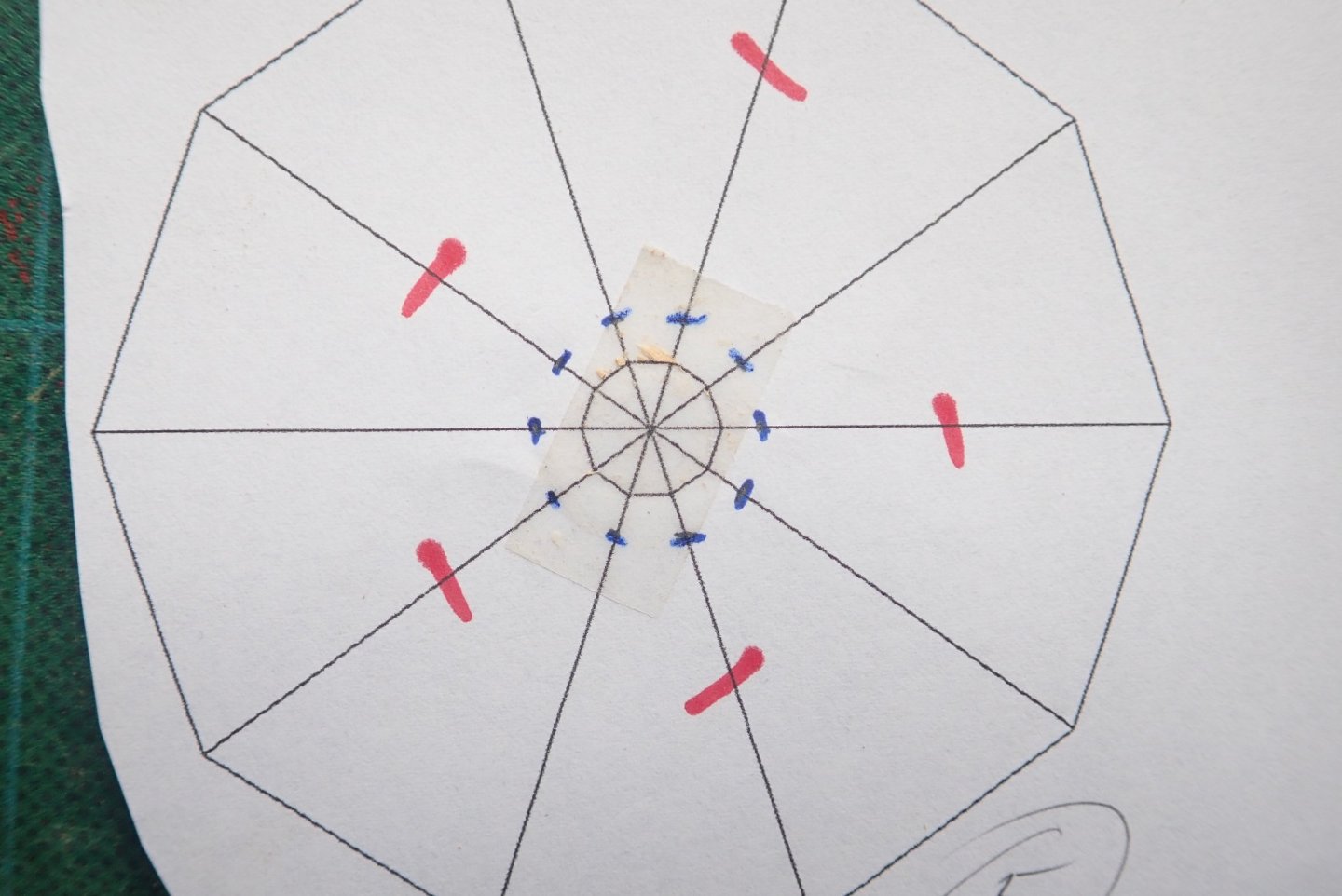
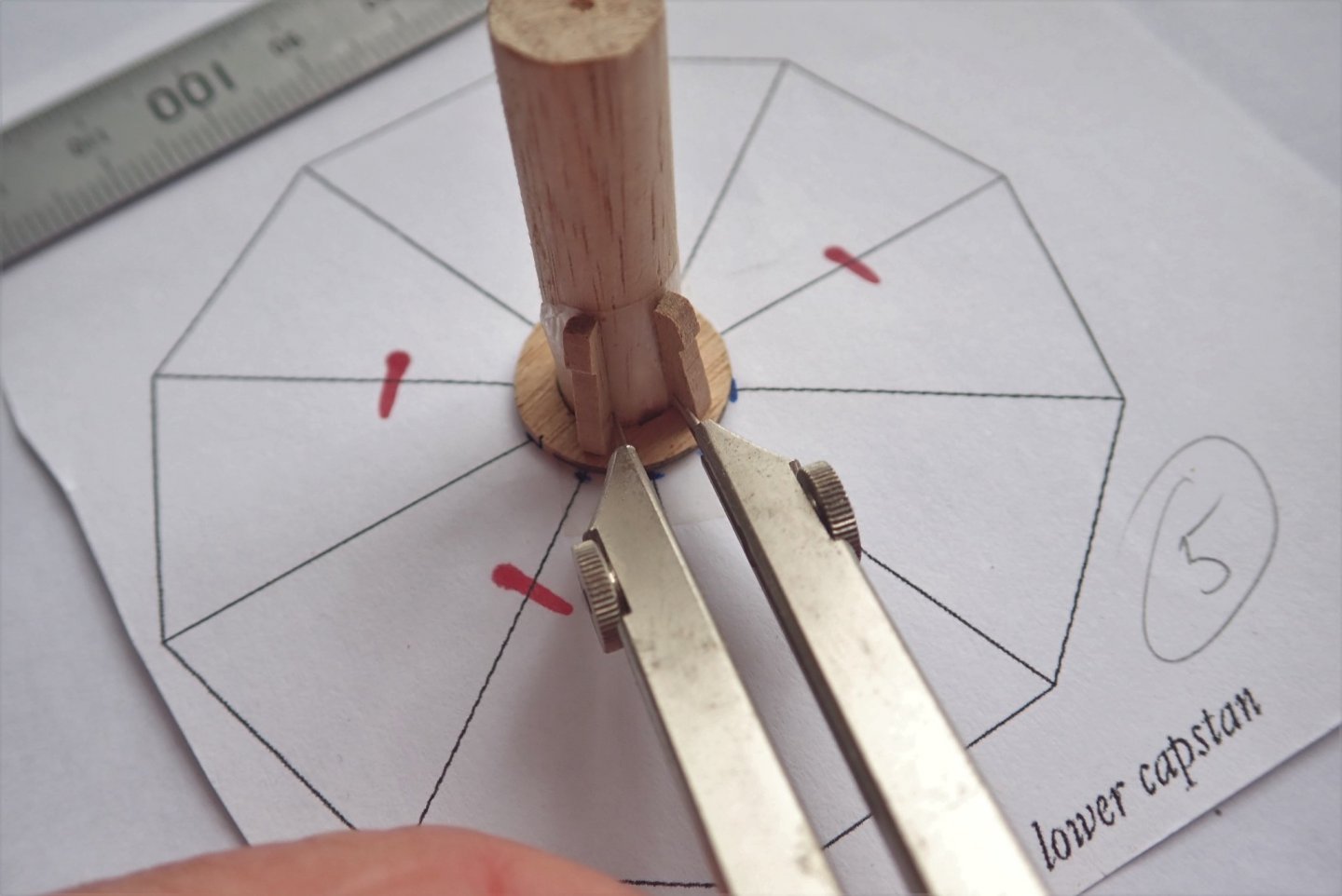
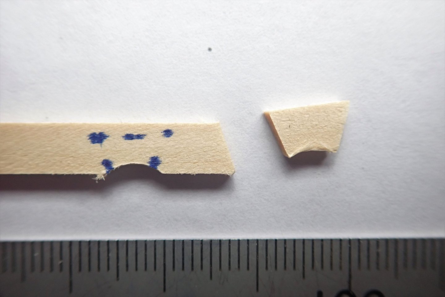
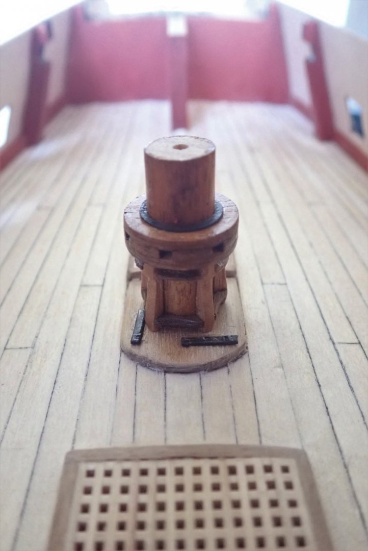
Thanks for the likes and the comments. The capstan on the upper deck. I’ve been making this on and off over several weeks, and though I didn’t document the actual making of it, I decided to give this description with a few photos of how I did it. The dowel for the central column (the barrel) was cut long enough so that it reached up to the quarter deck, as I intend to make the two capstans look as if they are joined. I wasn’t satisfied with the kit supplied whelps, as they were too thin according to TFFM. I tried gluing two together to get a more reasonable thickness, but messed up a couple. I wasn’t happy with the appearance of the plywood edges either, so made a new set of whelps from walnut. A suitable number of blanks were cut to length, then sandwiched together with kit whelps on each end to be templates. Small amounts of PVA were used to hold everything together while the blanks were shaped using files and sandpaper. Once formed, the glue was dissolved with isopropyl alcohol. This method is basically the same as I used when making wing ribs for model aircraft way back when. It is also the way Mugje made his top and butt planks for the deck of his Pegasus (here). The next step was to glue the whelps (five according to TFFM) equally spaced around the barrel. The TFFM very nicely provided me with a diagram allowing me to do this easily. But before I could do this, I had to get a spacer onto the bottom of the barrel as it goes through the deck slightly, and the whelps have to be at deck level. One of the kit provided parts proved to be just what was needed. The blue marks on the diagram allowed me to center the barrel and it was held in place with a piece of double-sided tape. The whelps were then carefully glued to the barrel using gel CA. Once all the whelps were in place, I made the chocks (not supplied at all in the kit). One of the sanding drums I have for my Dremel was the same diameter as the barrel and was used to put a shallow rounded notch in a strip of walnut. The required width of the inside edge of the chock was measured using dividers and this was marked on the strip. The width of the outer edge was similarly marked, allowing for the approximate 3mm between inner and outer edges. The strip was then cut to give a wedge shaped chock that was kept deliberately over-length to allow for its outer edge to be shaped later. The thicker lower chocks and the thinner upper ones were all made this way and glued using gel CA. Some gentle sanding was often required to give a good fit. Once the glue had thoroughly dried, I used a second, larger diameter sanding drum to give the lower chocks their concave outer edge. The convex outer edge of the upper chocks was done using a sanding stick. The trundle head was assembled using kit-supplied parts and glued in place. A simulated iron reinforcing ring was made and glued on top of this. The scratch built whelps with the kit ones at each end. The diagram from TFFM. The blue marks allowed me to center the barrel. The barrel with its spacer, held on the diagram by double-sided tape. Two whelps are in place, not glued in this example but again held by tape. Measuring the width of the inner edge of the chock. The wood strip (limewood in this example, not walnut as actually used) with the rounded notch and the shape of the chock marked. A sharp pointed pencil was used, not the fine point felt pen as shown. A chock after marking and cutting, and well overlength. Finally, the completed capstan on the deck. Cheers.


- 104 replies
-
- 5
-
-
- pegasus
- victory models
- (and 2 more)
-
That looks very good Starlight. Like you, Tim and many others, I had to trim a few mm off the front of the patterns and redo the hole for the bowsprit. And like Tim, I slightly cut the outside edge of the bulkheads that have to be removed before gluing the patterns in place. Cheers
-
Very well done with the margin plank. I'm glad my suggestion worked for you. Cheers
-
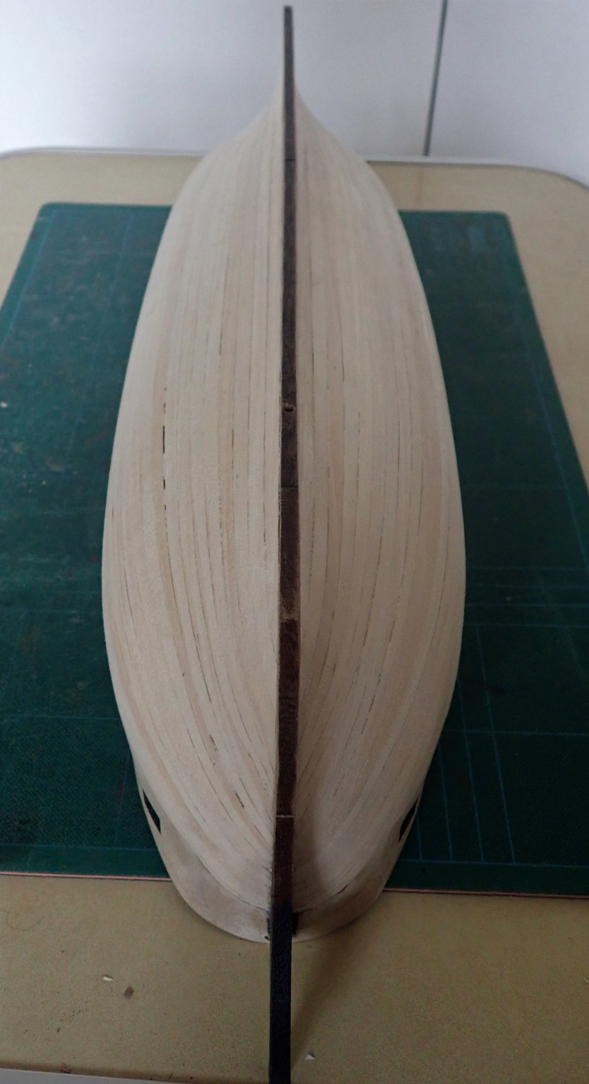
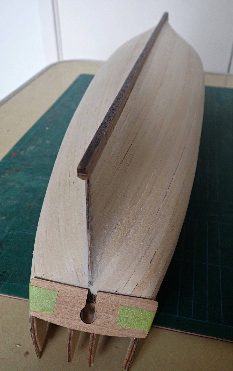
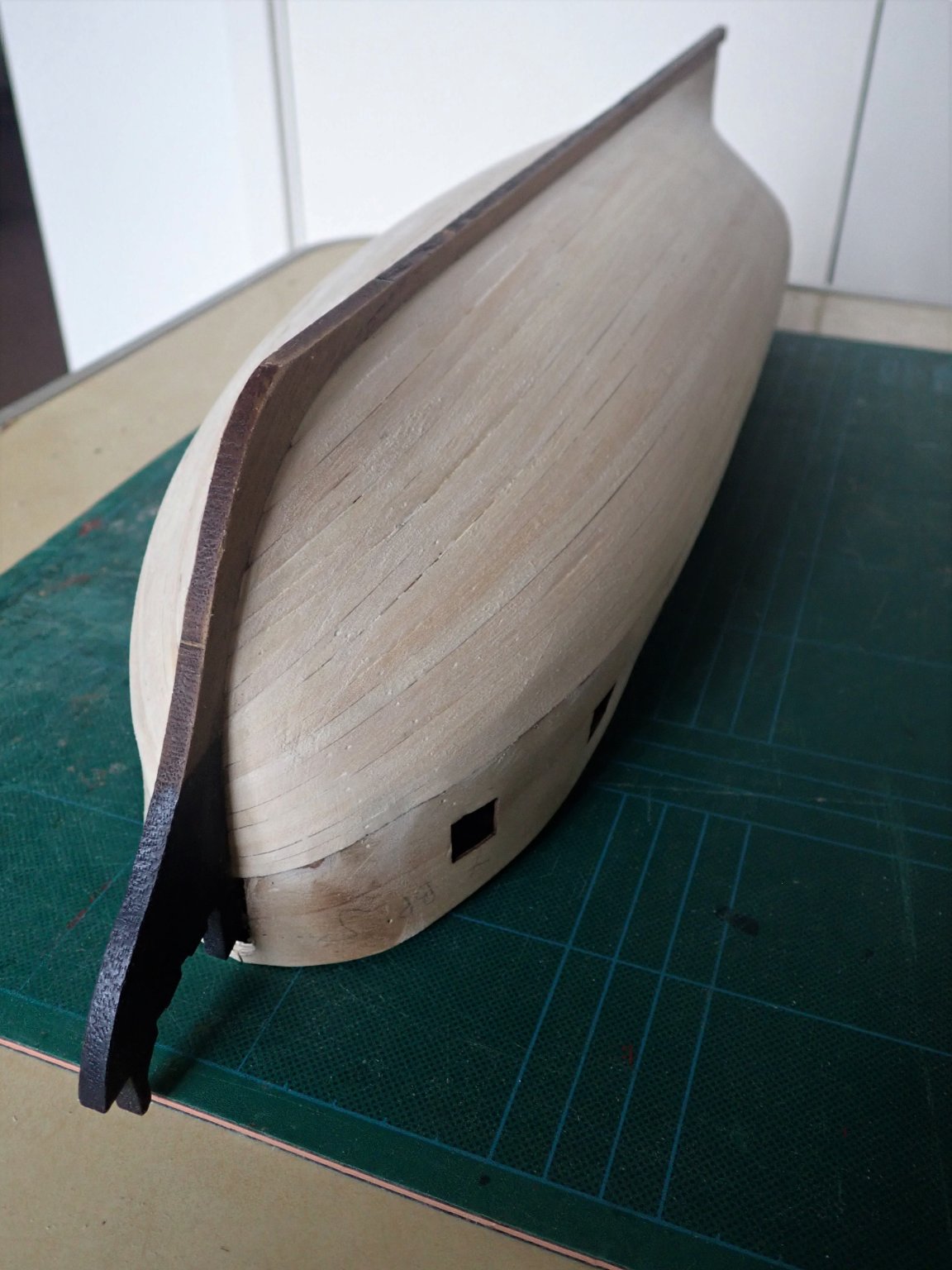
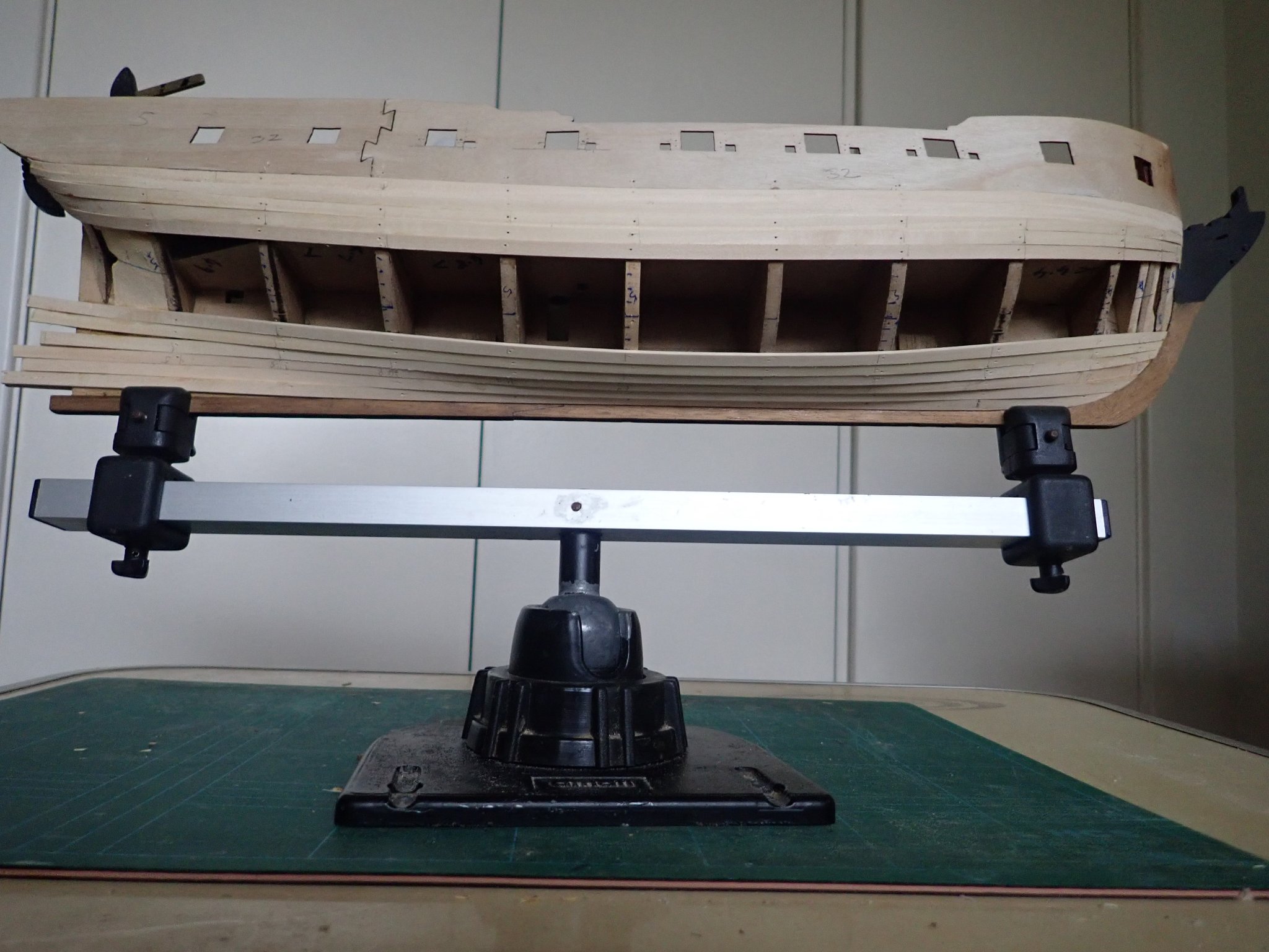
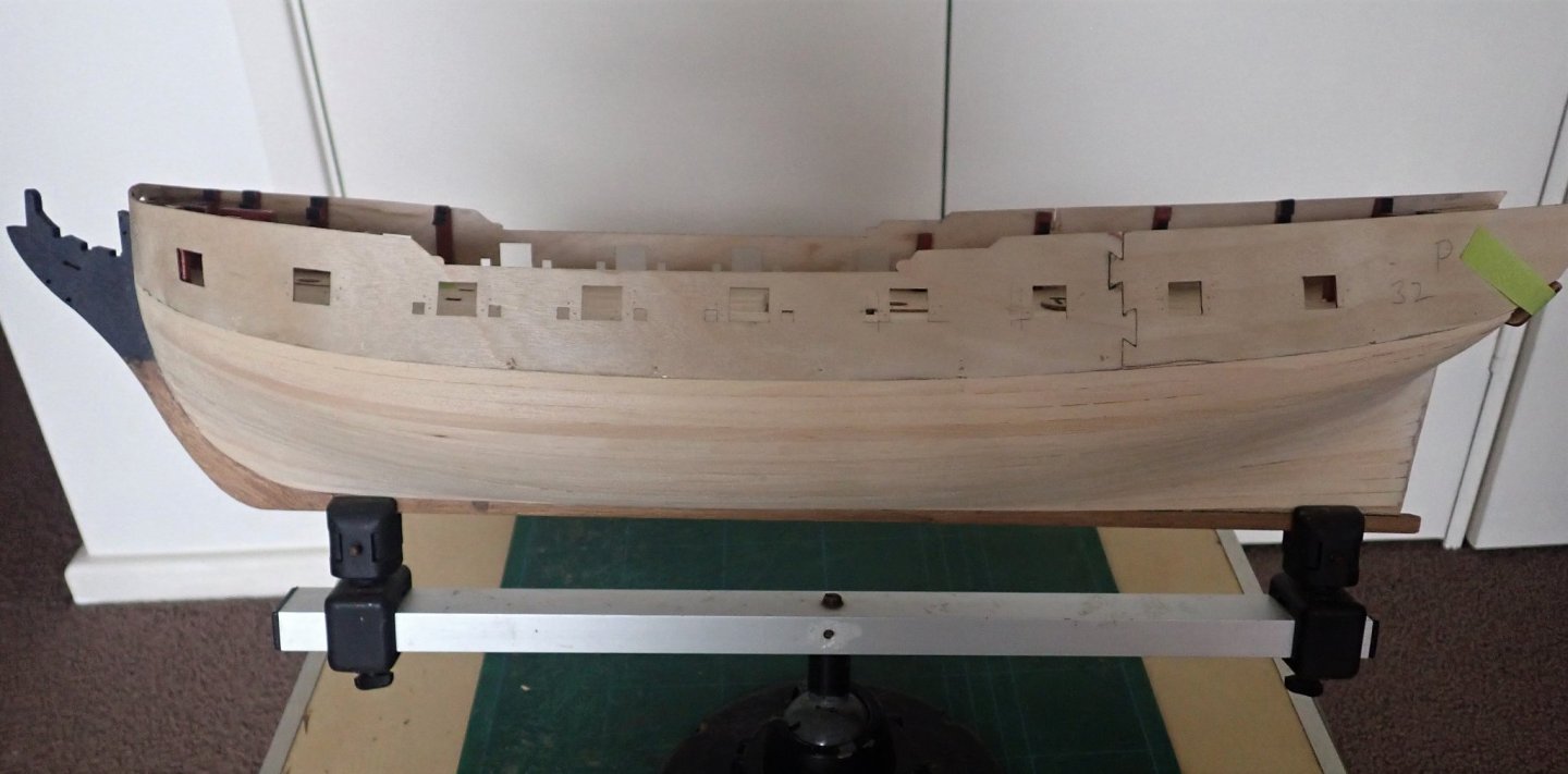
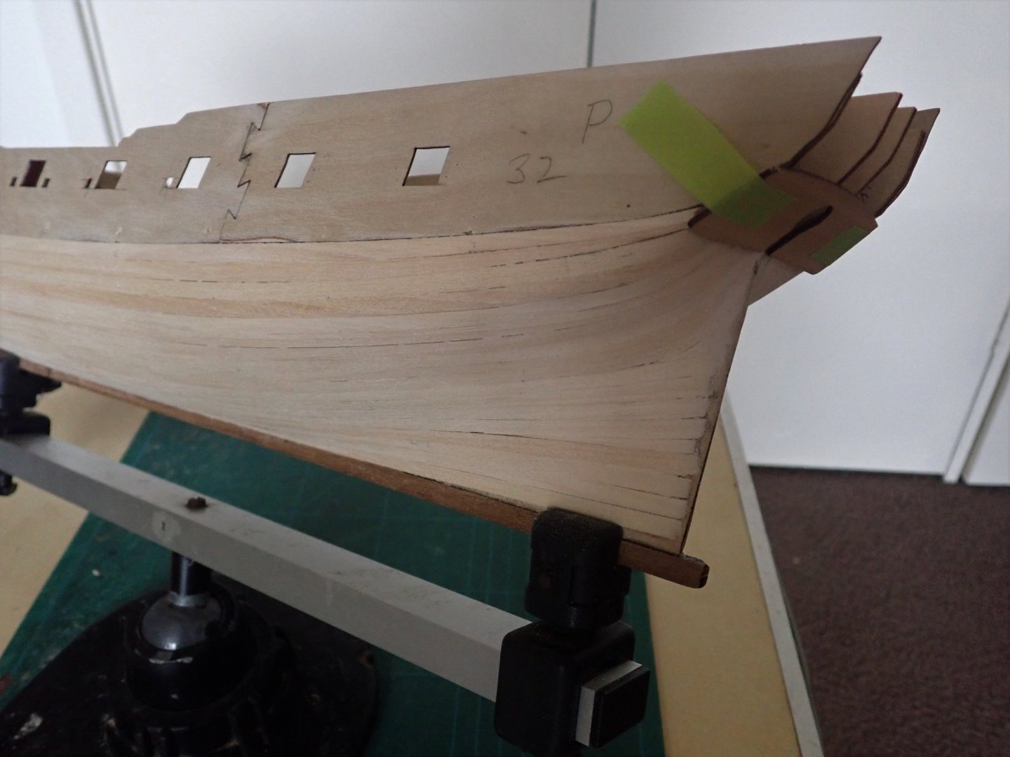
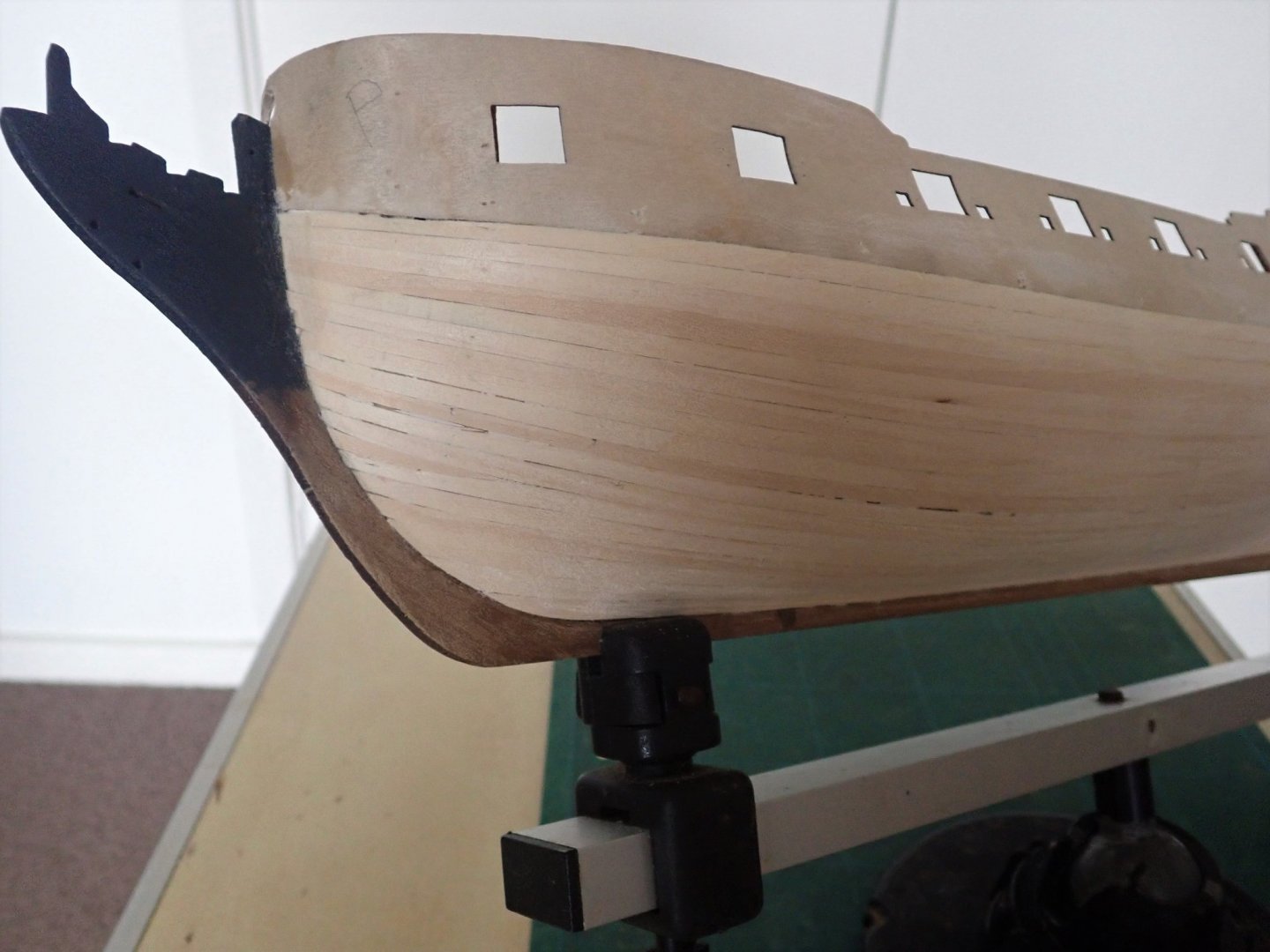
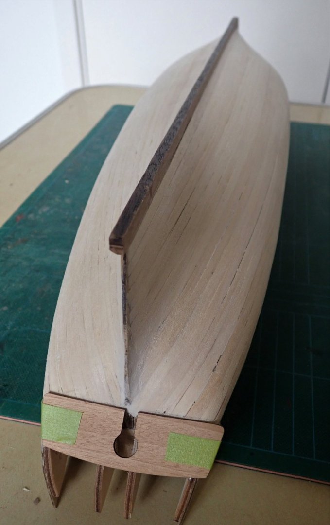
Thanks for the comments and the likes. The first planking has been completed. The photos show the result. There are some minor gaps between planks which I haven't bothered to fill. The only filler (putty) I used was in two small patches at the stern. Note that the counter was only held in place by two strips of masking tape and moved while the photos were being taken. Cheers


- 104 replies
-
- 9
-
-
- pegasus
- victory models
- (and 2 more)
-
It's coming along nicely. Cheers
-
Hi Tim, Just to add a couple of things to what Spyglass has said. I've nearly finished my first planking, and I've done what you are planning to do. One difference is that I fastened the garbord strake (the one against the keel) and the one immediately under the gunport patterns in place first. Then I measured and subdivided and used tick strips, several of them. The garbord strake needs a good deal of twisting and definitely needs soaking. Do not let this rise too much at the bow otherwise you will have problems later with the subsequent planks. I added strakes from top and bottom and after every couple or so, I remeasured and adjusted the amount of taper if necessary. I over tapered the planks towards the bow and I'll need to insert a triangular stealer. Stealers are common at the stern so don't worry when your strakes won't fit neatly against one another - let them run smoothly. Spyglass doesn't use one, but I use an Amati hand crimper to put the curve into planks, though I also soak and clamp if I think this will be better. One thing to note is that the limewood strips (mine anyway) are a whisker wider than 5mm. It's not much but it's cumulative. Cheers
- 164 replies
-
- 2
-
-

-
- fly
- Victory Models
- (and 4 more)
-
Hi Glenn, Yes I know I'll be doing a fair bit of tapering, but there will be more planks at the stern than amidships, simply because of the greater area there. There will be several stealers, simple triangular ones as this is only the first planking. After I lay two strakes, one up from the keel the other down from the gunport pattern, I remeasure the gap and vary, if necessary, the amount of taper. It's all good fun. 😄 Cheers
-
Yes, making those nicks and then trying to bend the strip may work but it wouldn't be easy to get a neat finish. I had some wider strips (8mm) which were sufficiently wide to fit between the bulkheads and could be shaped to conform to the inner and outer curves. You just might get away with using three or four Tanganyika strips laid edge to edge without any caulkIng, particularly as you won't see the margin plank once the fore and quarter decks are in place. Cheers
-
Nicely done Starlight.
-
Very neatly done.
-
Tim, you're doing really well. Your positioning of the rear patterns looks to be spot on. It's hard to tell from the photo, but I think you may have to bevel the last two bulkheads (at the stern) even more. Limewood bends fairly easily if you soak it for a while. Cheers
- 164 replies
-
- 2
-
-
-
- fly
- Victory Models
- (and 4 more)
-
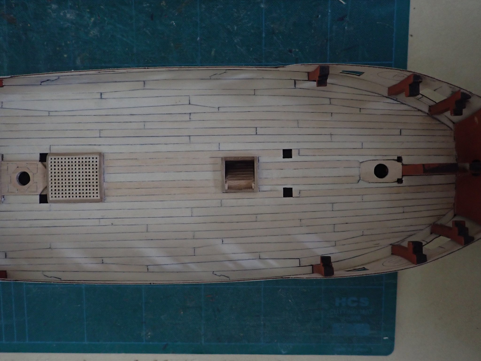
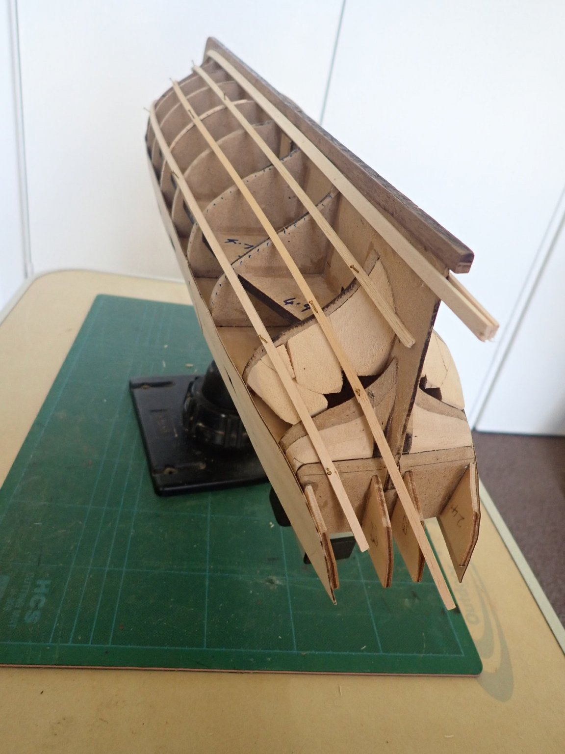
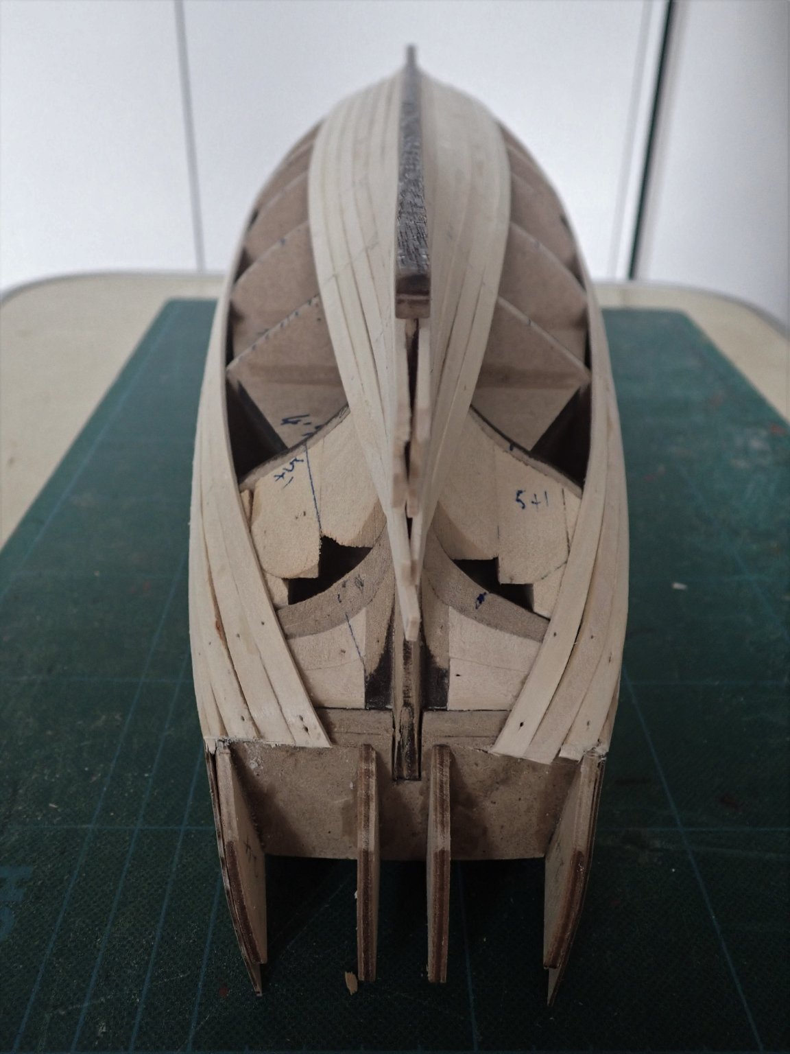
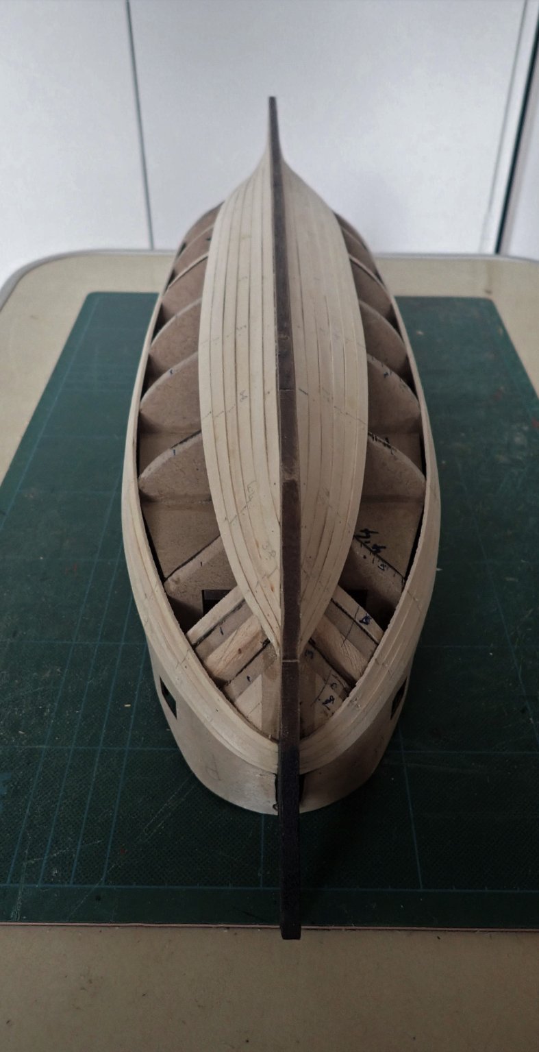
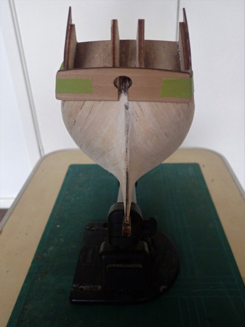
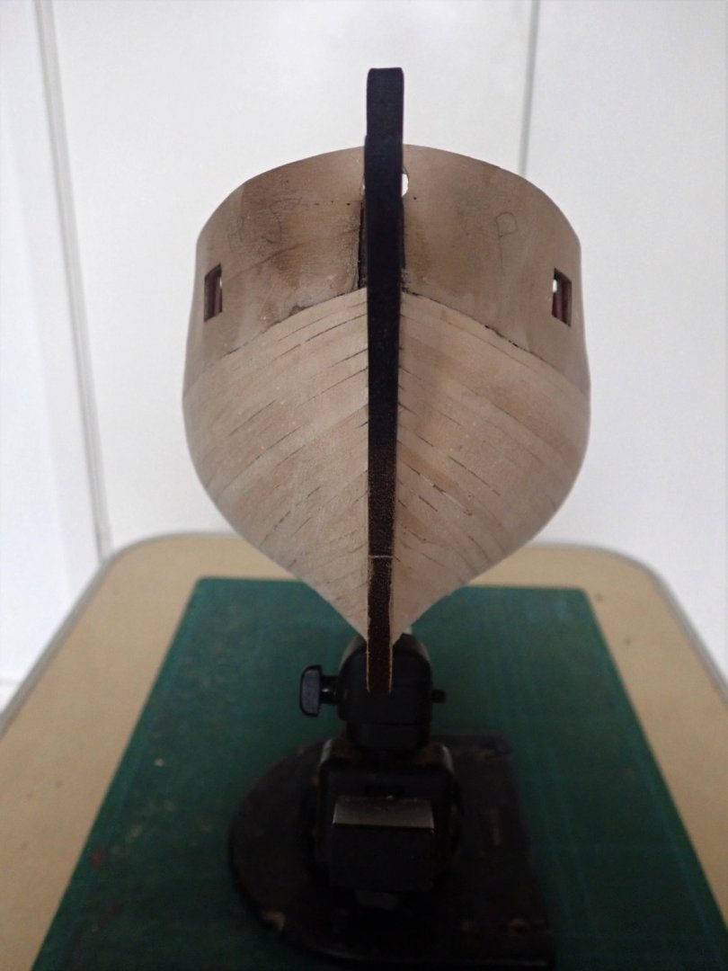
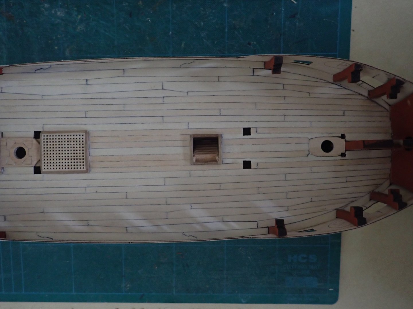
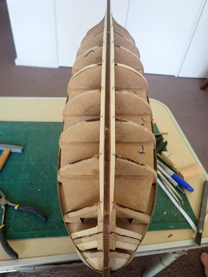
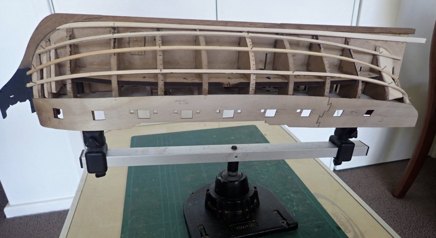
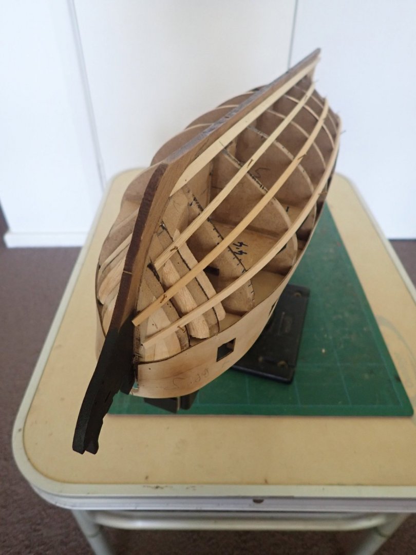
Thanks for your comments. Once the gunport patterns were in place, I completed the deck planking. The ladder in the forward hatch can be seen. Before starting the hull planking, I decided to make and install the ladder in the forward hatch. I did this now on the very reasonable assumption that I would drop the ladder down the hatch before actually gluing it in place, and it would be difficult if not impossible to retrieve it via the hatch, if the hull was closed off. Sure enough, I did drop it a few times. The supplied wood for the ladder was a bit mixed. The sides were ok, but the wood for the treads was 1x2mm. This was both too narrow for the treads and too thick to fit into the grooves already cut into the sides. So some 0.5x3mm was utlised. I commenced the hull planking by gluing the garboard strakes in place, making sure that they did not rise too high at the bow. At the stern, I allowed the strakes to find their own run, without trying to force them towards the keel. This resulted in a gap which may need to be filled with a triangular stealer. As most of this area has to be sanded heavily before doing the second layer of planking, I may get away without having to do so. There is nothing unusual about needing a stealer at the stern and I expect more will be needed. I then pinned some battens along the hull to get an idea of how the planking should run. I wasn’t entirely happy with how these looked, even with some adjustments, so used paper tick strips between the garboard strake and the lower edge of the gunport patterns to mark the bulkheads as well. The garboard strakes glued and pinned. Three battens in place and it can be seen that the bulkheads have also been marked after using tick strips. Planking has progressed, and has been going quite smoothly. The appearance of triangular gaps at the stern was expected and will be filled with stealers if necessary. I know some builders end the planking at the stern somewhere between the bearding line and the stern post, but I decided to run the planks out past the stern post - makes it easy to keep the symmetry. I know though I'll have to do more sanding to reduce the thickness of this planking. That's it for now. Cheers.


- 104 replies
-
- 5
-
-
- pegasus
- victory models
- (and 2 more)
-
I lost track of you Russ, I was wondering if you'd finished the launch. Nice work. Cheers
- 14 replies
-
- 1
-
-
- panart
- armed launch
- (and 2 more)
-
You're doing really well and you have a good base for your second planking.
-
To make this more secure, particularly into MDF, drip thin CA into the hole first. Be careful. Let it dry thoroughly, then screw the bolt in. The CA hardens the wood.