Beef Wellington
-
Posts
2,249 -
Joined
-
Last visited
Content Type
Profiles
Forums
Gallery
Events
Everything posted by Beef Wellington
-
 Congratulations Jesse on completing such a fine looking model, have really enjoyed following along with you.
- 1,306 replies
-
- 4
-

-
- syren
- model shipways
- (and 1 more)
-
Looking good David. I think you're at a nice stage where you can work on a number of things simultaneously, which can be nice to keep changing the pace, especially the all interior main deck fittings and cannons. One thing I'm sure you've read from all the other Diana builds is the challenge with getting appropriate alignment at the stern, and how this ties into the lines of the wale. I tend to start planning as soon as I can and leave final installation until as late as I can to avoid as many unexpected surprises as possible. That may allow you to make any fine adjustments needed to the placement of the wale which doesn't need to go on just yet. I'd also recommend figuring out the placement of the mid-ship beams which will require you cut into the lime planking and nice to get this out of the way without having to worry about damaging anything down the road.
-
HMCSS Victoria 1855 by BANYAN - 1:72
Beef Wellington replied to BANYAN's topic in - Build logs for subjects built 1851 - 1900
Great photos Pat, really looking good and shows off all of the excellent detail work. I'll be honest, and I'm no expert, the air vents did not jump out at me as being oversized at all when I saw them and considering the period.- 1,018 replies
-
- 5
-
-
- gun dispatch vessel
- victoria
- (and 2 more)
-
Hawker Typhoon by Asat - Airfix- 1/24
Beef Wellington replied to ASAT's topic in Non-ship/categorised builds
Looks great Lou, how much of this detail will be visible - I hope lots! -
Hawker Typhoon by Asat - Airfix- 1/24
Beef Wellington replied to ASAT's topic in Non-ship/categorised builds
Hi Lou, looking great and I'll follow with interest. What will the final model look like? -
Studding sail booms and yards
Beef Wellington replied to robdurant's topic in Masting, rigging and sails
Hi Rob, the various studdingsail booms were simply stored on their respective yard, but secured inboard to the actual yard with a lashing. The lower booms are secured in the iron hoops on the forward part of the channels so they can rotate outboard - whether these were "permanently" stored there is a question. I suspect that these would have rigged according to need, as they seem to be rather exposed and awkward alongside the hull given interference with the deadeyes - just my thoughts as can't find any reference to this. -
Peter, some real eye-candy there! Great work on the decks, the nibbing looks very neat, and an inventive solution to the margin plank. Seems like you got a nice batch of Tanganika with very little grain. That's an awesome model of HMS Cottesmore as well. BTW - you must be very proud to have commanded such great ships, couldn't help but notice the Ton class, can't quite make out the pennant - HMS Nurton?
-
Be careful what you say, rationality is in the eye of the beholder! The more exaggerated wales on British ships would help counteract hogging. More of a concern on British ships which typically were more heavily constructed given the differences in expected role and tactics.
-
Hi Wahka, I think I understand you question. I believe you will need to install a walnut sternpost, which is 5 x 5 mm if memory serves. Therefore you will want to have the external planking to be around 5mm thick where it meets the sternpost, so you have some options. The most extreme would be to thin the bearding at the stern to around 1mm thick to allow for 2x 1mm lime wood strips, and 2x 1mm walnut 2nd planking. Unfortunately the pictures from when I was at this stage are lost from my Snake log, but I believe that I thinned the actual keel to around 3.5mm, and then cut a notch following the same bearding line and sunk the first planking strips into it. The bottom picture in post below illustrates this but on a different build. That approach should save you some sanding, and is probably a little safer approach. Once you have the first planking installed, you can then thin more and using the shape of the hull as a guide. Hope this helps.
-
This is indeed a fascinating subject, and unfortunately I have nothing else to add other than musings. Intuitively it seems inherently a risky design to have the pump directly feed into water outside the keel as shown. This would make the entire pump case a watertight integrity hazard, failure anywhere in the pump casing below the waterline could result in severe, if not catastrophic, flooding. While this is clearly something used today in ship design, metal is much more of a robust engineered solution allowing multiple fail safe options in the event of accident or failure.
-
Well done, looks great! So what's next?
-
According to TFFM the elm tree pumps also terminate in the bilge, very similar to the low point of the chain pumps. Your identification of the placement for the elmtree pumps is consistent in the photo above.
-
You have a very fine model coming together there Helli.
-
Looking sweet Eamon, that's a very sharp looking false sheave.
- 1,039 replies
-
- 1
-
-
- ballahoo
- caldercraft
- (and 2 more)
-
Hi Jim, your analysis seems sound. The pumps would all have been contained within the well around the mainmast, and would need to be forward of the chain pumps and aft of the pillar with the rhodings for the Axeltree. Any other location would interfere with the working of the fore and aft winches when installed. The only remaining question is why they are missing from your reference material, and that's a mystery. I would include them if I were in your shoes. As to the number of chain pumps, I can only speculate its down to the size of the ship. There is ample evidence for there being 4 on 1st and 2nd rate ships of the line, and similarly 2 on smaller 5th rates, so logically there must be a cross over point wherever that is. Don't think I've seen any discussion on that, but 2 doesn't seem unreasonable on a 50 gun 4th rate.
-
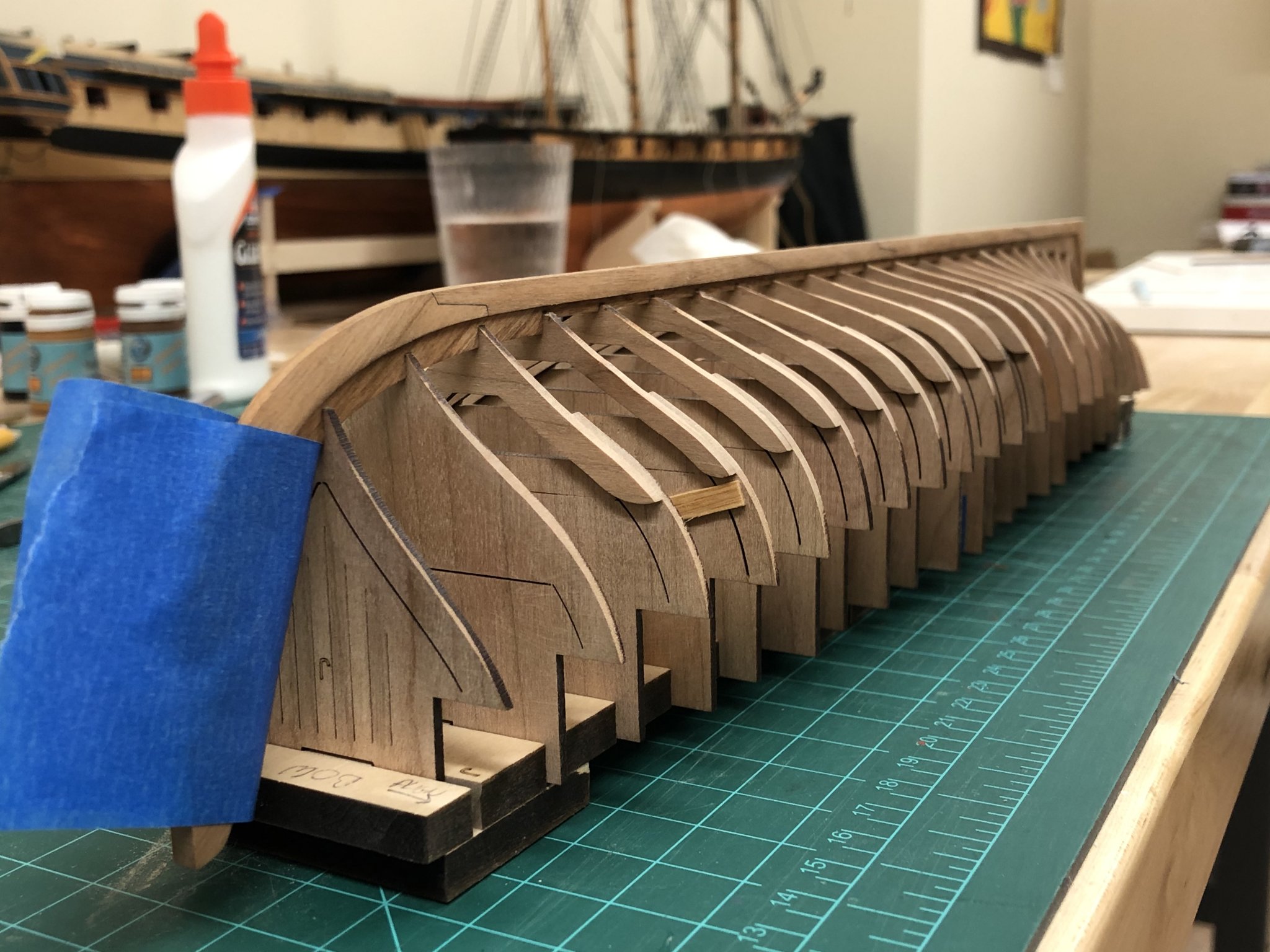
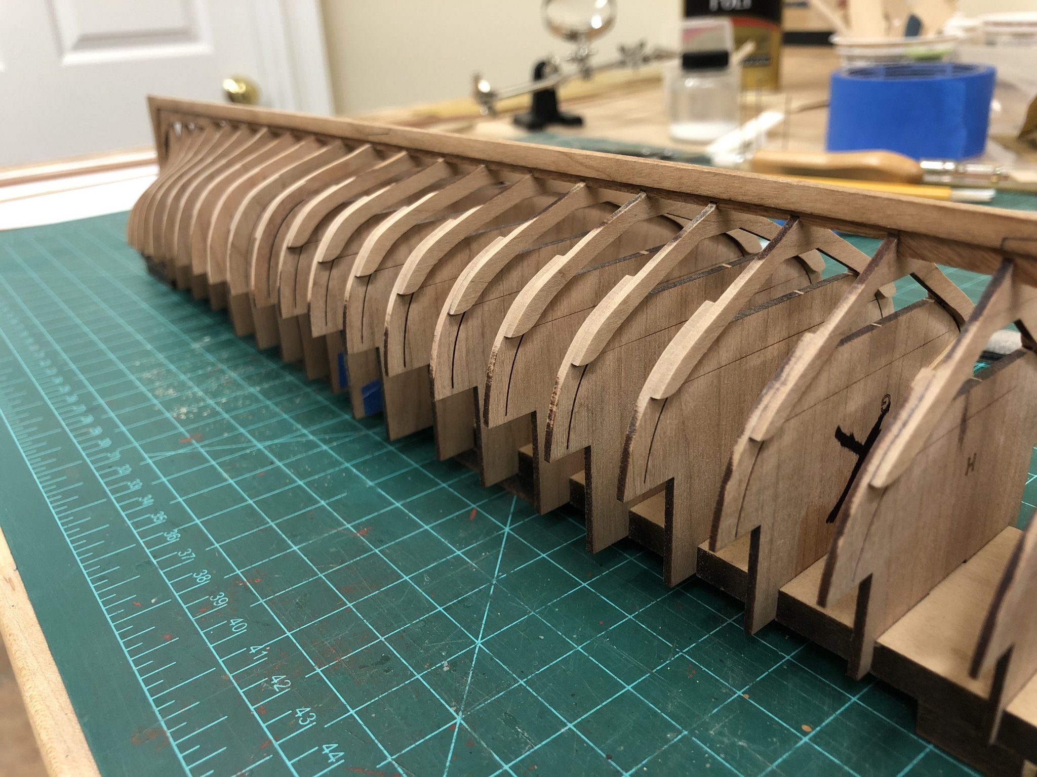
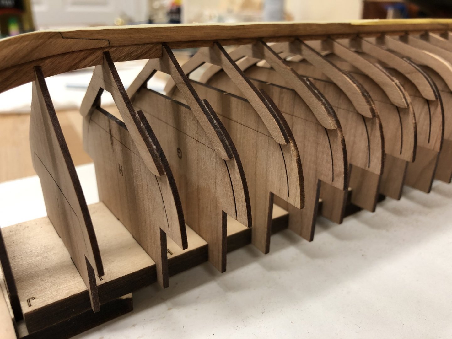
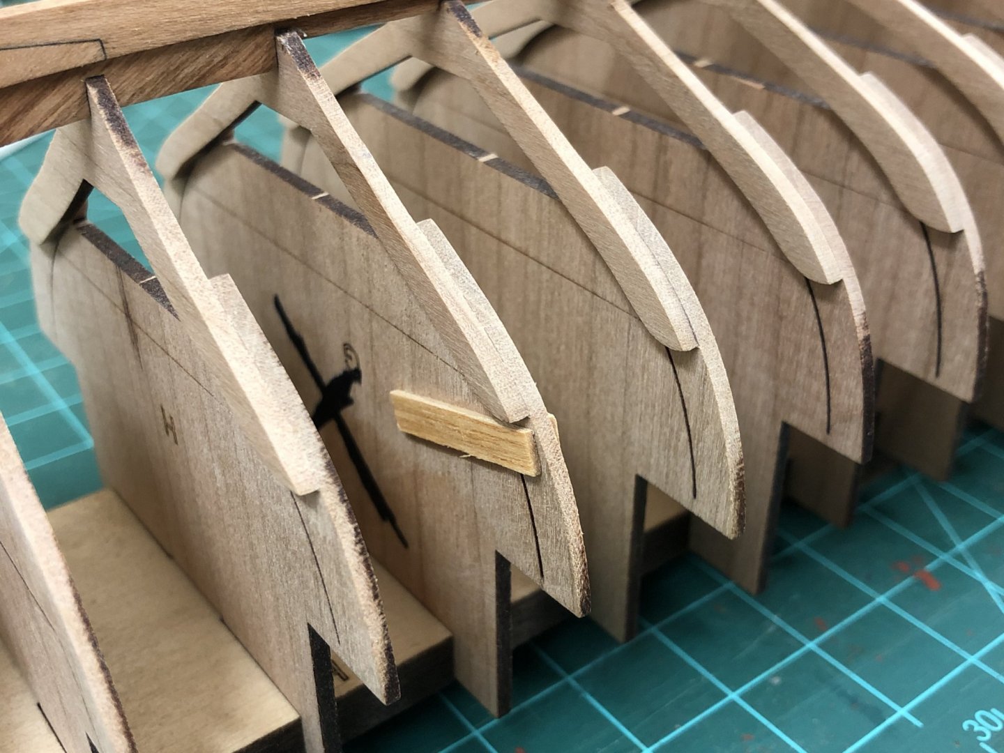
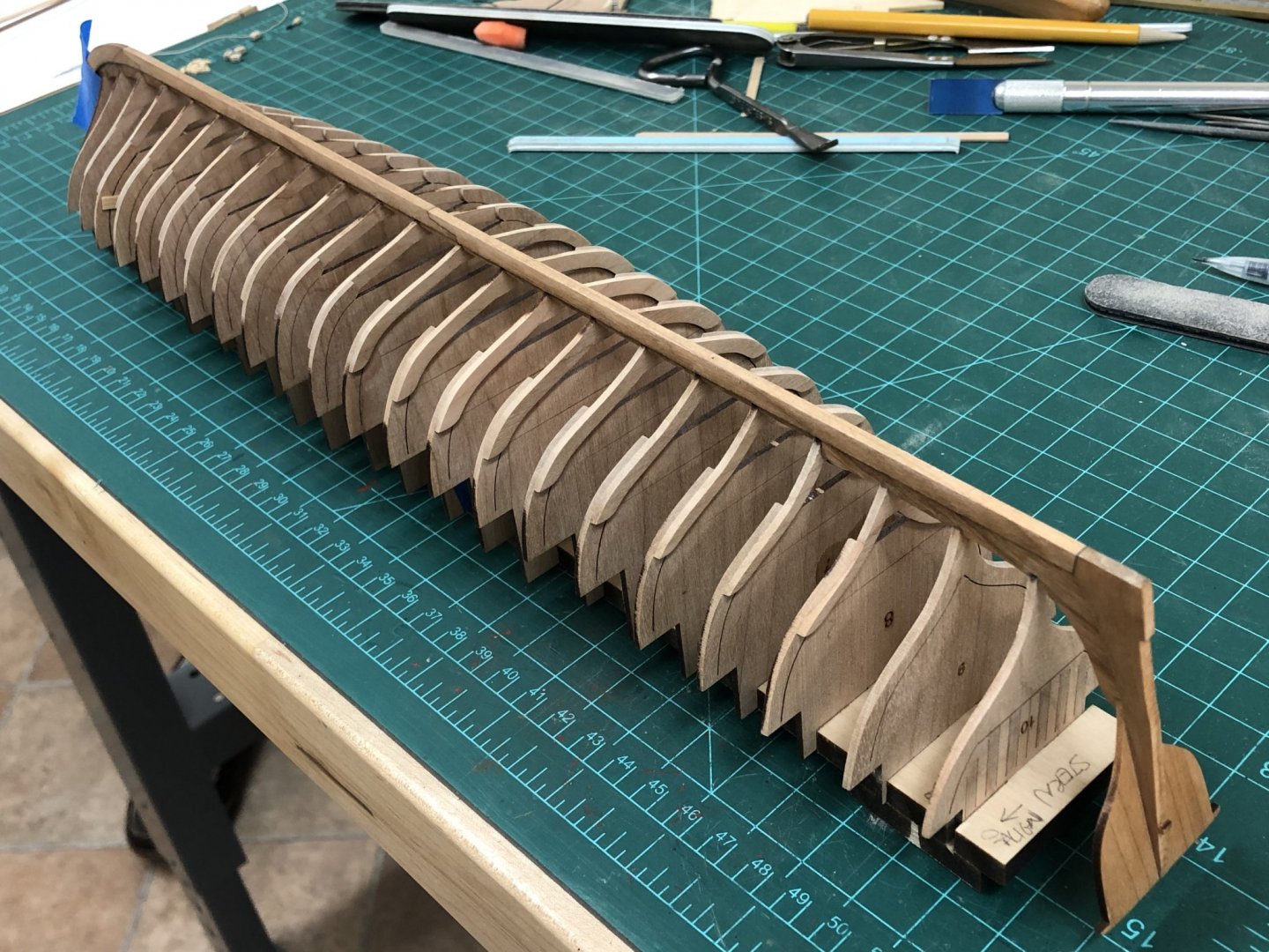
Glad to have you follow along Jean-Paul, I very much enjoyed reading through your QAB log, a model to aspire to. Frame Installation: Additional work done on the keel was some final shaping of the stern post, finishing of the keel taper, installation of the transom, and a coat of wipe on poly for protection. One thing I have noticed with cherry is the grain can cause optical illusions. In a couple of places I know the surface is as smooth as I can make it, but the grain makes it appear quite course still. I had been working on making up the frames for some time, for many this simply requires to a frame foot to be glued to its corresponding futtock after cleaning off some areas of laser char. Pretty simple as each has its own guideline which is well explained in the instructions. The grooves on the assembly board needed to be filed out a little to allow the frames to be inserted, primarily due to the thickness of the wood and the slight angle introduced by the laser cutter. I think this is good opportunity to share an observation about the kit. It is definitely a well thought out design with very clear instructions, however, that does not mean that some experience is not required as I was soon to find out....I'm sharing my experience below because every other build log of this kit seems to go together without a hitch, so a little humbling that I found this so problematic. First Attempt: First off, the assembled frames were inserted and the keel glued according to the instructions making sure that frames aligned well beforehand and that the bottom of the frame floor were at the right height to sit in the keel, and best effort to keep this in a straight line as well as by eyeball trying to keep what will be the top of the frames smoothly aligned. Everything seemed to work fine, and once the glue had had sufficient time to set, I started to fair the frames. This is when a first inkling of problems started, I noticed that some of the frames were moving in their slots, and upon further investigation some the frames were not really secured solidly to the keel. Although the planking will definitely add to the strength, I wasn't convinced the frames would be rigid enough to allow planks to be installed. Given the construction method, its not possible to remove and re-glue a single frame, so the isopropyl alcohol was brought out to remove all the frames.... Second Attempt: Upon analysis two things became clear. I hadn't used enough glue in the joints, and that my judgement of what 'play' was needed for the frames in the build board was wrong (the instructions say that these shouldn't be too tight or too loose), but it was really only trying to go through the process of fairing that indicated what this should be. Some tape was added as suggested in the instructions to more rigidly seat these, and the process to align and glue repeated (using more glue this time around). Unfortunately, in the final stages of seating everything, I somehow placed too much pressure on frame G and the result was that the frame foot broke in two places, and the small tabs on one side of the futtock popped prematurely (these are weak by design to allow easier removal at a later stage). The isopropyl alcohol was brought out once more to remove all the frames........I don't have any photos of this, honestly I was too despondent to record it... Third (and so far final attempt): After examining the break, the cherry had broken with the grain and looked like it could be repaired. These are delicate pieces, but I don't think will be subject to much stress once the planks are on. The breaks were located on each side of the foot where there is a small dark element of grain, and can just be seen in photos below. The small tabs on the futtock were also given a tiny spot of glue, and to hopefully provide a little more strength a splint was glued to the central section to absorb some of the shearing forces that will be unavoidable while fairing the frames (this is NOT glued to the actual futtock itself). So far, things seem to be back on track, and work has resumed on fairing the frames which is where things sit currently.


-
HMCSS Victoria 1855 by BANYAN - 1:72
Beef Wellington replied to BANYAN's topic in - Build logs for subjects built 1851 - 1900
Quite a bit to catch up on Pat, but as others have said your metalwork and soldering are just fantastic. Looking forward to a few more overall beauty shots hopefully soon 🙂- 1,018 replies
-
- 3
-
-
- gun dispatch vessel
- victoria
- (and 2 more)
-
Hi Rob - I put a link to the main yard plan below the picture, easy to miss... I think that gets to the art of seamanship and ship management....a longer topgallant mast would have allowed a larger sail area to be spread to harness the wind, but which (together with a little more weight) would provide more of a turning moment about the center of bouyancy. This could be offset with more weight lower in the ship to maintain stability but that is probably the art of the true seaman to continually seek the optimal balance of speed, handling and cruising endurance for the task at hand.
-
Vane, as soon as the new thread arrives I'll be back on it, have no fear. Unfortunately, or fortunately, the journey for me is more satisfying than the destination, and I find the huge difference in skills being worked to be mutually beneficial. I'm enjoying working with wood again on the QAB building a foundation and is a nice complimentary distraction to rigging - here I find the stock thread supplied to be the main source of frustration which is a shame....and while all that is going on the back of my brain is thinking about how to approach the planking and headworks on Jason, as well as approach the rope coils and anchor puddening on Snake etc. Darrell - thanks for the encouragement and kind words. I'll hopefully get some time soon to peruse your build log as well.
-
Great update as always Rob, wheel definitely looks better and know that will be on my list when I get there, I already have some of Chuck's Syren wheel kits to see how they turn out. Good call on the coaming height, believe these would have had a much lower profile on quarter and foc'sl and been of lighter build and less of an obstruction. The upper deck would be much more susceptible to water ingress, and a method of helping preventing water entering lower areas in heavy seas or rain. BTW, hope you don't mind me posting but probably more relevant to you in the near term, but while browsing in the NMM I found the following print of Diana's main yard. Lot more complexity to it than is commonly portrayed, and think the iron hoop and wooldings to be a feature I don't really recall seeing on other models. https://prints.rmg.co.uk/products/ship-plan-of-hms-diana-1794-main-yard-j5526?_pos=20&_sid=0141b51f9&_ss=r
-
Coming back to the original question on the use of the Ensign staff, I think current Royal Navy (and probably other Commonwealth, likely all other) provides the answer. By tradition, an ensign is flown from the ensign staff only while not underway either in harbor or at anchor together with the union jack at the for jack staff during daylight hours. Modern ensign staffs similarly pivot per Druxey's description to avoid any entanglement with the variety of modern operations that occur in the stern area. While underway, the ensign is flown from a different location wherever the primary mast structure is, which is both most visible and least encumbering. Taking this practice back to the days of sail, it would seem logical to infer from this the same practice (although I suspect the ensign staff would be removed entirely while underway) and with the sea going location being flown from the gaff peak and the ensign staff lowered or stowed.
-
Thanks all for the continued interest and kind words, unfortunately progress has been halted due to running out of certain line. I have an order into CMB for some more but with the current situation may take a while, work will resume as soon as the supply chain catches up...hopefully I can get some Queen Anne Barge time in in the interim.
- 800 replies
-
- 2
-
-
- snake
- caldercraft
- (and 1 more)
-
Interesting subject Andy, definitely want to see how this plays out.
-
Beautiful result BE, I do love the colour tones of your builds and cleanness of your rigging...and very educational to boot . Looking forward to seeing your Queen Anne Barge take shape, more QAB can't be a bad thing!
- 335 replies
-
- 2
-
-
- alert
- vanguard models
- (and 1 more)
-
Hi Gremreeper - Unfortunately I don't think there is a magic, secret solution to your problem. Wood strip, even as thin as 0.5mm just wont really bend in multiple directions readily, you don't mention whether you have tried soaking the planks or not, if not, then worth a try. Other than that, I think CaptPoison's suggestion to use a drop plank terminating in the area of the bulge is something worth pursuing. Another option would be to try and first heat bend a strip using a hairdryer to give a strip a slight curve across the width of the plank, and then try to fit on the curve of the hull, this may be sufficient to prevent breakage. And, if you haven't already, strongly recommend reading the planking tutorials as they are pretty comprehensive and provide great information on approaching this tricky step.