
HOLIDAY DONATION DRIVE - SUPPORT MSW - DO YOUR PART TO KEEP THIS GREAT FORUM GOING! (Only 20 donations so far - C'mon guys!)
×
.JPG.ca33079f5815b861e67b9c2cccd37982.JPG)

Blue Ensign
-
Posts
4,564 -
Joined
-
Last visited
Content Type
Profiles
Forums
Gallery
Events
Everything posted by Blue Ensign
-
 Thank you Glenn and Derek. It's always worth keeping all that pe fret and also any hard wood fret, comes in handy for scratch building many small items. Hi Derek, yes I mix my own, pre-made wop is a bit of a rip -off in my opinion. I use oil based polyurethane varnish diluted with white spirit. There is a load of info on making your own wop on You Tube. 🙂 B.E.
- 261 replies
-
- 4
-

-
- muirneag
- vanguard models
- (and 2 more)
-
What a little beauty, she'll have you wrapped around her paw in no time.😄 B.E.
-
Beautiful job Michael, I really must get around to starting mine which has been sitting beneath the bench for a while now. Your most excellent build has given me the impetus to make the barge my next project. Well done. B.E.
- 221 replies
-
- 1
-
-
- queen anne barge
- Syren Ship Model Company
- (and 1 more)
-
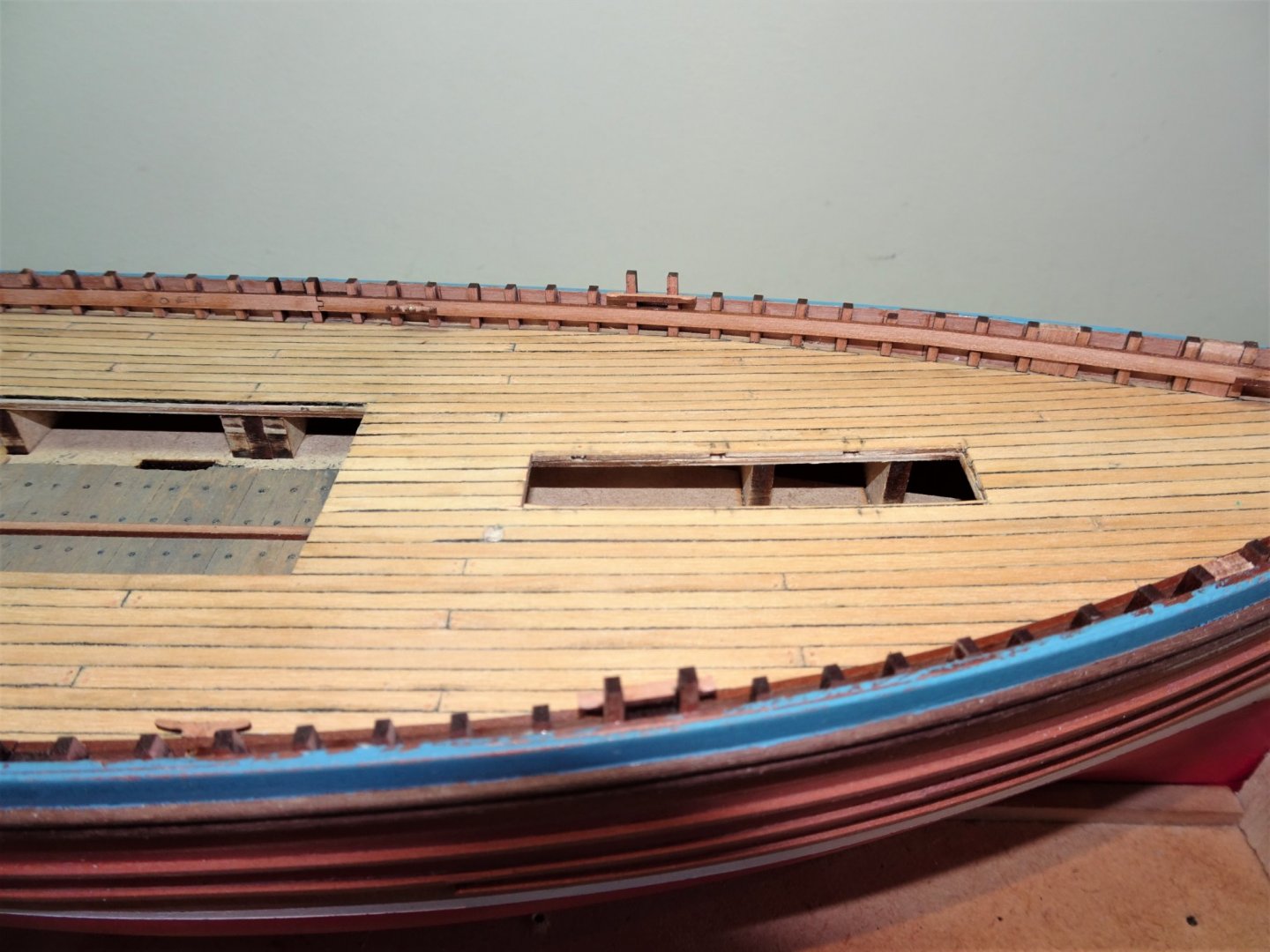
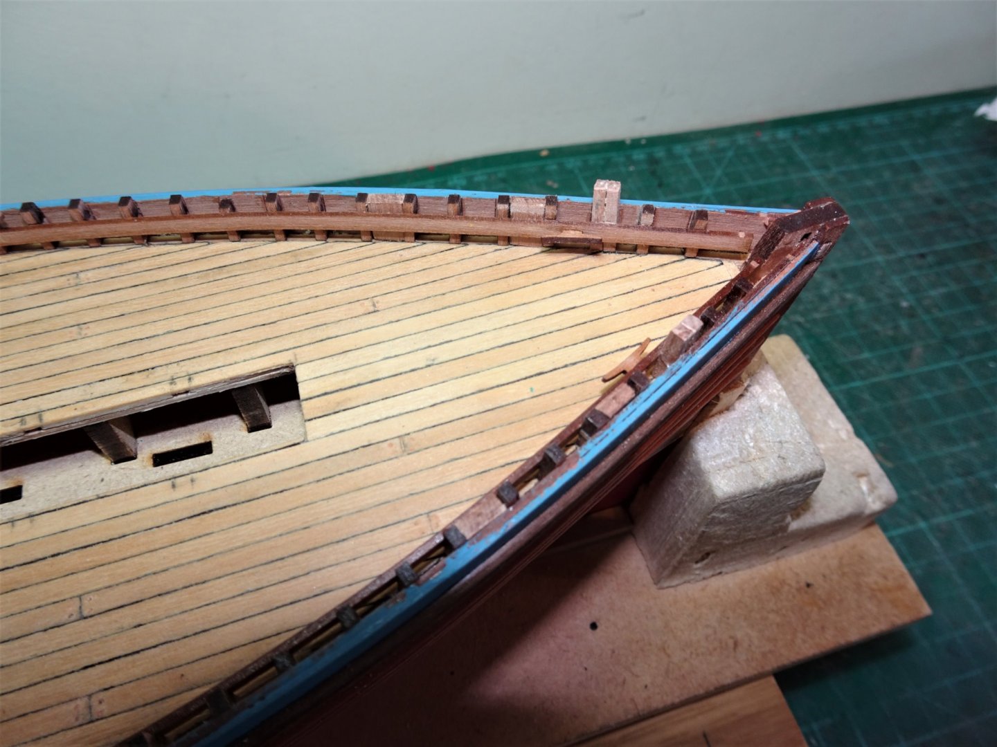
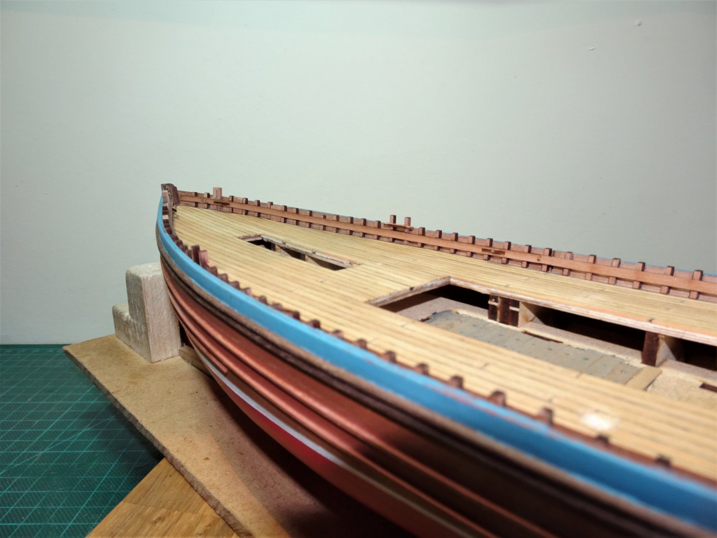
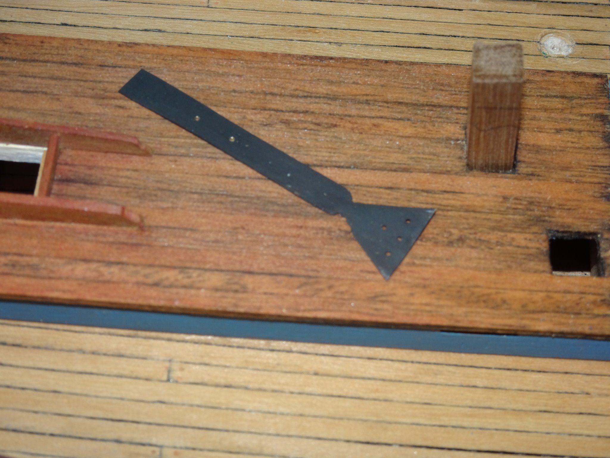
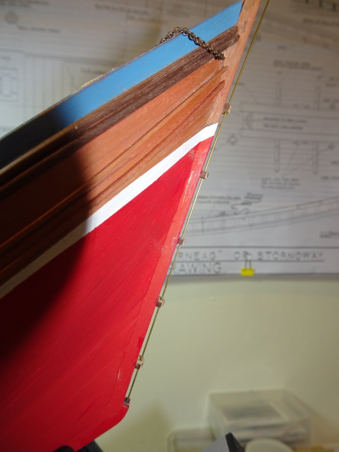
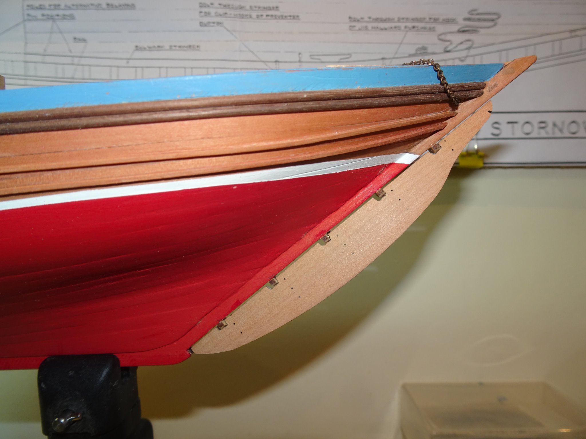
Post 23 Detailing the internal stern area. On the real boat a 1” thick iron strip ran from the stem along the keel and up the stern post where it was riveted to the head of the sternpost. This was fitted as protection when grounding. The kit provides a nicely etched Bow plate which replicates the stem iron but is not carried around the keel or sternpost. The flange on top of the stern post would be visible so I replicated one. 8136 I used the 0.20mm brass fret from around the decoration etch of my Pegasus kit to make the plate. This was then chemically blackened. 8142(2) The stern area nearing completion. A coat of wip has been applied to the stern woodwork. The iron stern plate has been pinned into position Along the Starboard doubler at the stern are three iron plates which take sockets for items I’ve yet to understand the purpose of. 8155(2) The kit provided Coal bunker hatch is inset into the deck. A nice little item this, once blackened it looks the part. 8170 The smaller and plainer pump deck plate can be seen forward on the starboard side just aft of the mast partners. 8146(2) At the bow there are two knees to be fixed. 8161(2) Usually I seal the deck with a flat water-based varnish but I have decided to leave it unsealed. The Boxwood planking will darken with age which is my intention. 8163(2) Yet another fill, sand, and repaint job needed to improve the rail finish but hull completion is not far away. B.E. 22/10/20

.thumb.JPG.6c675f74bd34360fabee3ef4377dffc5.JPG)
.thumb.JPG.6097af4345bac6e3e495da7743e62057.JPG)
.thumb.JPG.c70b08fb9846d5468202758b56e86f17.JPG)
.thumb.JPG.0bb133daac003591e2b17b350582a2b8.JPG)
.thumb.JPG.76676bd522f6d64dac6acd3599d62c03.JPG)
- 261 replies
-
- 17
-
-
- muirneag
- vanguard models
- (and 2 more)
-
As I'm currently into fishing boats Yves, I will follow your build continuation with interest. She looks really good as you have her currently displayed, standing in frame only, and what an elegant setting. Regards, B.E.
-
👏 👏 👏👏 Very well done Glenn, she looks beautiful. B.E.
- 778 replies
-
- 4
-
-
- cheerful
- Syren Ship Model Company
- (and 1 more)
-
Thank you Richard for having a stab, there are also variances of the meaning of Muirneag, which is also named for a hill on the Isle of Lewis. MUIRNEAG (Lewis). G. diminutive of muirn, cheerfulness, joy. Name of a beautiful hill ; the only one near here, which the fishers can see far out at sea. Another definition repeated in several publications is as below. When Alexander "Sandy" MacLeod ordered his Muirneag ("Darling Girl" in Gaelic & also the name of a prominent hill near Stornoway) in 1903, it was his second McIntosh built Zulu - the first being the SY 1108 Caberfeidh, being launched from the Portessie yard by John McIntosh in January 1896. "Sandy" had by 1903, already a reputation as a fine fisherman & mariner, his Caberfeidh being the first Stornoway Zulu to go the English herring fishing. This reputation was enhanced as he fished Muirneag continuously up to the outbreak of WW2, refusing to convert her to engine power & thus becoming one of the last links to the past, being the last British herring drifter to fish under sail power alone. I would like to think that 'Darling Girl' is the meaning given that Sandy Macleod obviously had a great affection for her over many years of ownership, and in 1947 at the age of eighty, took her to sea for the last time before she was broken up. Still, enough of this nostalgia, I've a Zulu to build. 🙂 B.E.
- 261 replies
-
- 2
-
-
- muirneag
- vanguard models
- (and 2 more)
-
Thank you Thomas, By all accounts they were fast and handy vessels, except perhaps in harbour where they proved very heavy to manoeuvre. I find it amazing how only a few men handled these large luggers in the less than hospitable North Sea, and effectively removed all the sailing gear once fishing started. That large out of view rudder was also removed and stored on deck, something I find difficult to visualise. How could the pintles be located on that sharply raked sternpost, particularly in a lively sea. Thank you Martin, We are alike in that respect, Mrs W is convinced that I live in the 18thc in my head. When asked what is my favourite music genre I always reply I love the music of the 80’s, and Wam (Wham) in particular. I quickly follow it up with Wolfgang Amadeus Mozart and the 1780’s. 😉 I am far more familiar with ships of the 17th/18thc than fishing boats of the early 20th. There are terms peculiar to North East Scotland that I still don’t understand. I’m still not sure even how to pronounce Muirneag’s name.🤔 Cheers, B.E.
- 261 replies
-
- 5
-
-
- muirneag
- vanguard models
- (and 2 more)
-
Very nicely done Richard, great detailing on the deck and fittings thus far.👍 Always a relief once the gunport pattern is fixed into place. Regards, B.E.
-
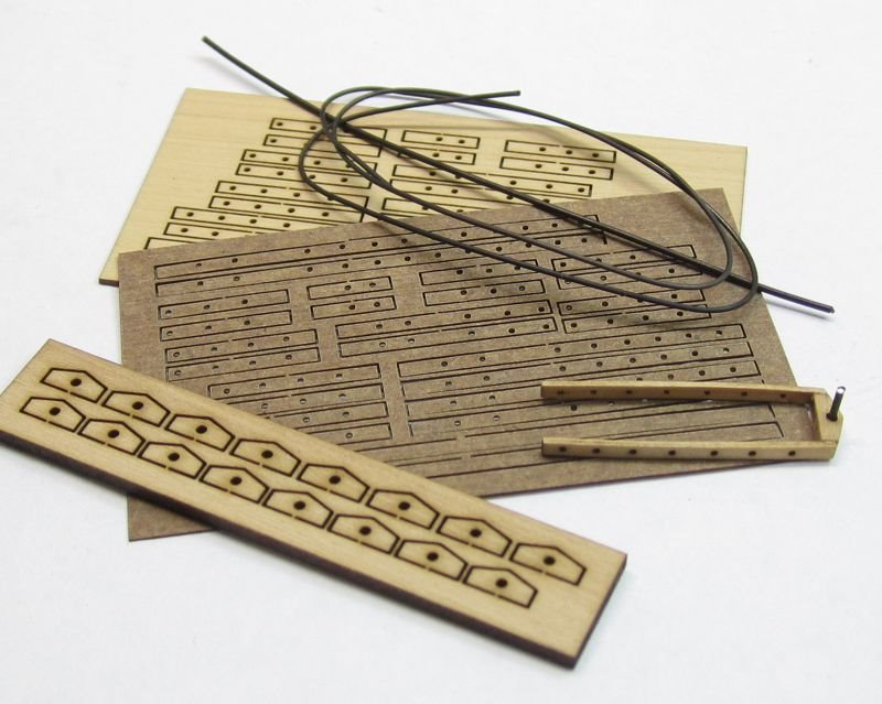
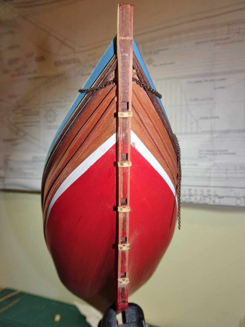
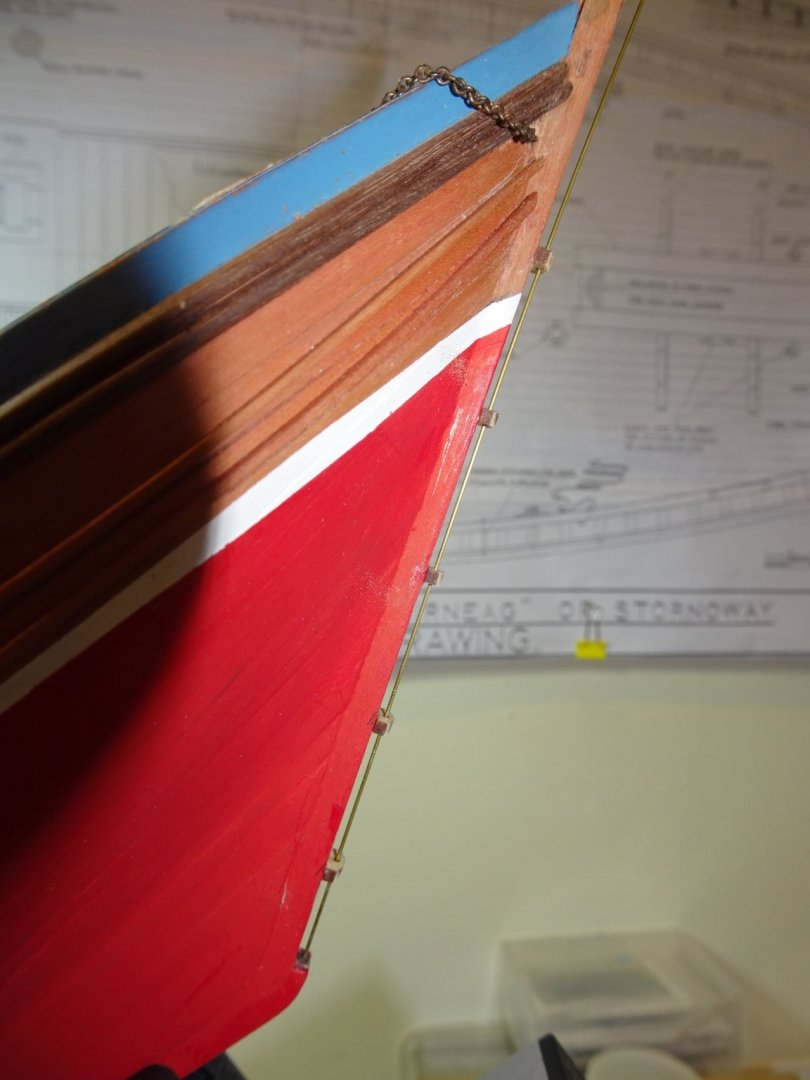
Thank you John 👍 Post 22 Fitting the Rudder. Chris has designed a simplified rudder attachment system which circumvents what can be a fiddly exercise. This has tenons on the rudder that slot into mortises on the stern post and hold the rudder in the correct position. The straps are then added to rudder and stern post to give the impression of a hung rudder. The alternative is to hang the rudder using pintles and gudgeons which is more authentic but a little more involved. To aid the modification Chuck (Syren ship models) sells a neat little rudder kit for his range of models which includes the Gudgeons and straps. These are ideal for a whole range of different model types and scales. 7991 The gudgeons are fitted to the stern post. It is important that the gudgeons are placed at the bottom of the mortises in the stern post for correct alignment. Once the glue has hard set the gudgeons will be shaped to suit. 7993 I use a length of wire to align the holes for the pintles. 8003 The rudder could do with a touch of fettling being tapered down slightly from top to bottom and from inboard to the outboard edge. The tenons on the rudder are removed and will be used to fill the now redundant mortices on the stern post. 7997 Pins have been inserted into the rudder to represent the pintles. 7999 With the rudder hung I can now attend to the painting and make the necessary adjustment to the white watercut line at the stern post. 8116(2) I’ll return to this later to add the straps to the pintles and gudgeons. 8128(2) She looks so much better with the rudder in place. 8130(2) I’m beginning to like this hull shape more and more Back to detailing the internal stern area. B.E. 20/10/20

.thumb.JPG.38cfc4cb808d21e94acee7fe50ad83b2.JPG)
.thumb.JPG.a7eed3bf1708e2b4c4d926b0159f1285.JPG)
.thumb.JPG.98417d874cb45c3be609ce17b02fa29b.JPG)
- 261 replies
-
- 15
-
-
- muirneag
- vanguard models
- (and 2 more)
-
Fascinating subject and a superb job. I have to admire your resolve and commitment to making all those figures, very well done. B.E.
-
Cutting holes on a deck
Blue Ensign replied to Rik Thistle's topic in Modeling tools and Workshop Equipment
Swann-Morton make very good micro chisels in 1mm and 2mm widths, I wouldn't be without them. 🙂 B.E. -
Cutting holes on a deck
Blue Ensign replied to Rik Thistle's topic in Modeling tools and Workshop Equipment
I used the preformed deck as a template , scored the outlines with a scalpel blade, and drill holes to aid the process. I didn't bother with the fiddly little cut outs for the timber knees to the Foremast partners, simply trimmed and glued them on the deck. Final finishing was done with sanding sticks made for purpose and micro chisels. I didn't find the process too onerous. Cheers, B.E. -
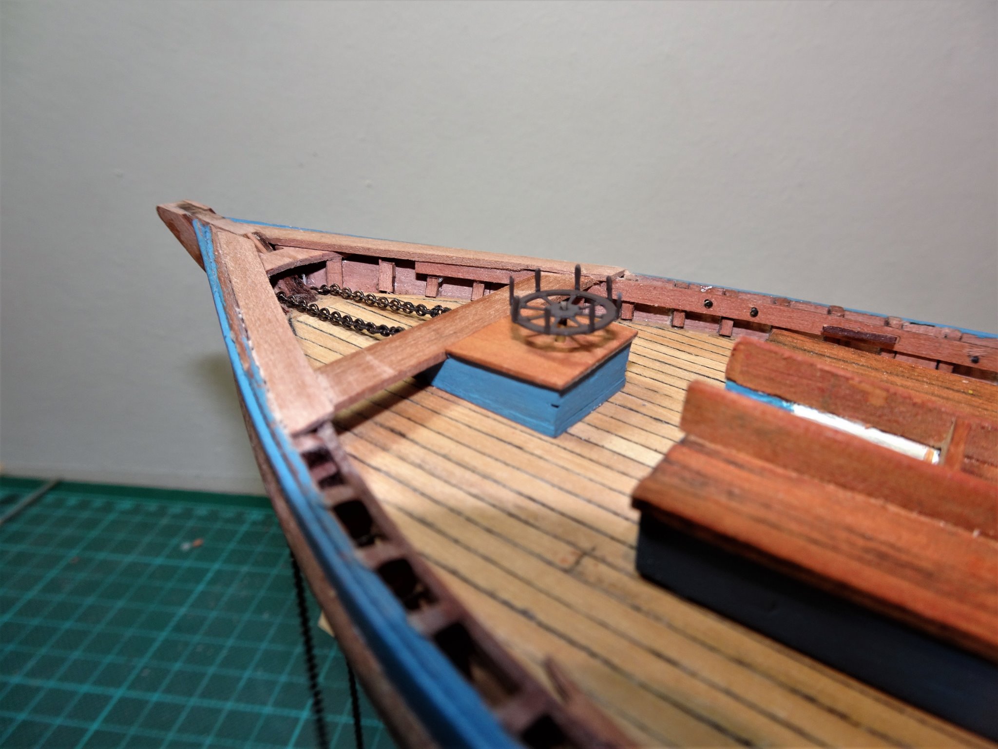
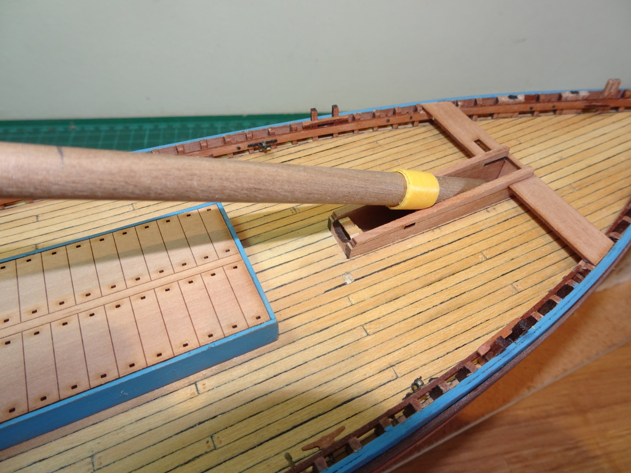
Post 21 Fitting the Steering Box. The Steering Box and related fittings present the most fiddly modification. The kit has a simplified all in one bench pattern (51) which incorporates a knee at the stern, doubler, and aft thwart against which the steering box butts. Muirneag differs both in the size and position of the steering box and the layout of the thwart, knee and doublers. There is a fair bit of trial fitting to get it all to sync together involving making separate parts. The first job is to get the position of the steering box fixed and to cut away some of the stringer to allow the aft thwart to sit down just below the level of the rail top. 7931(2) A spacer is used to position the box the correct distance from the companionway. 7922(2) The next step is to work out the run of the rudder chains thro’ the hull to the steering rods which protrude beyond the box. This particular chain I discarded in favour of a finer version with 26 links per inch. With that done the box can be safely glued down along with the aft thwart. 7934(2) The tricky business of shaping and fitting the doublers and stern knee can then be done. Why 'doublers' I don't know, they are for all practical purposes rails. For the doublers I am using 4mm Pearwood strip, edge bent to suit the line of the stern. These need to sit flush with the top rail line. 7947(2) Trial fitting the wheel, it always helps to have a scale figure handy. 7945(2) The height of the wheel above the box has been reduced as covered in Post 13. 7975 The wheel is quite a delicate item, so the stem slots into a micro brass tube fixed in the steering box which allow for its removal. 7978(2) It is a slightly simplified design with the spokes radiating from the hub simply bent into the vertical position to provide the hand grips. In reality the spokes extended beyond the rim and the hand grips were either bolted or welded in position. To replicate this at 1:64 scale would be a stretch too far for me. I will leave the final cleaning up of this area until the rudder is fitted which is the next task. B.E. 18/10/20
.thumb.JPG.2e0b84be3a70fe14f6d66b10ca1d70ea.JPG)
.thumb.JPG.bb94fb9308b24a23d948afc99c7fc27c.JPG)
.thumb.JPG.583ae0df452c41c6bc48db5d6309c850.JPG)
.thumb.JPG.3491feecd1172e891349456df72309a5.JPG)
.thumb.JPG.0b3152c869f1b991e979dde7e68f729f.JPG)

.thumb.JPG.2713819ab3d83196261e565ec83a363a.JPG)
- 261 replies
-
- 16
-
-
- muirneag
- vanguard models
- (and 2 more)
-
She looks good in the traditional black livery Richard, and the grey decks should provide a nice contrast. 👍 You have provided modellers with a good impression for those hovering between natural and black. 🙂 B.E.
- 49 replies
-
- 1
-
-
- Lady Eleanor
- Vanguard Models
- (and 1 more)
-
May be a blessing in disguise Tim, the kit provided stocks didn't look right to my eye, replacing them with the pattern in the aots book is the way to go.🙂 B.E.
- 436 replies
-
- 3
-
-
- vanguard models
- alert
- (and 1 more)
-
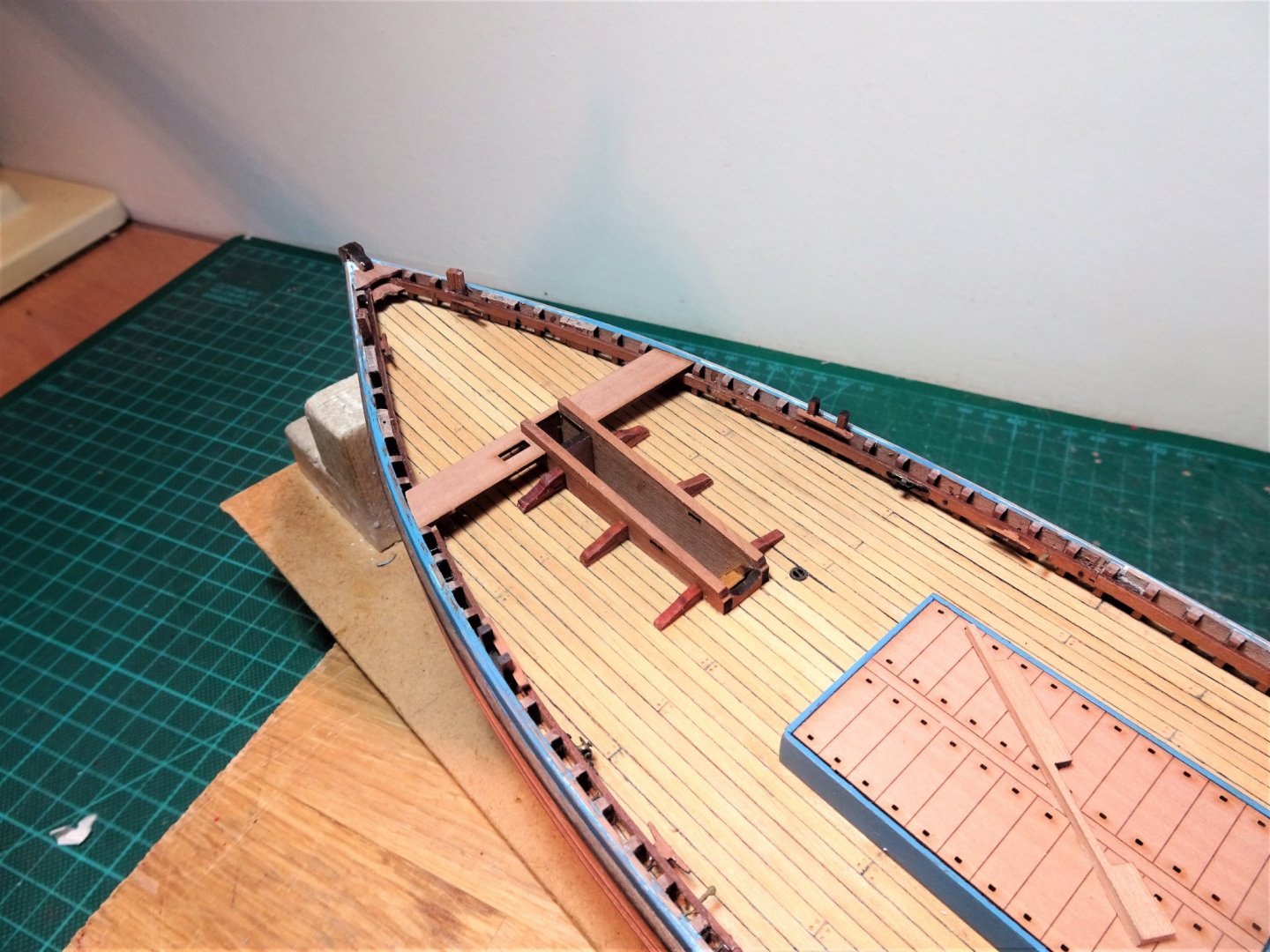
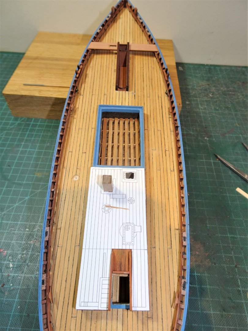
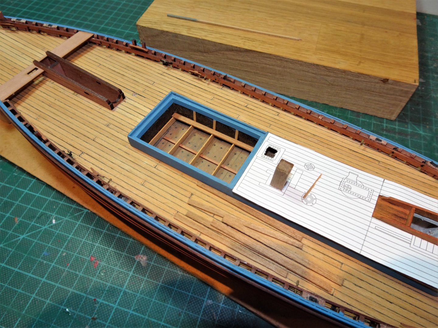
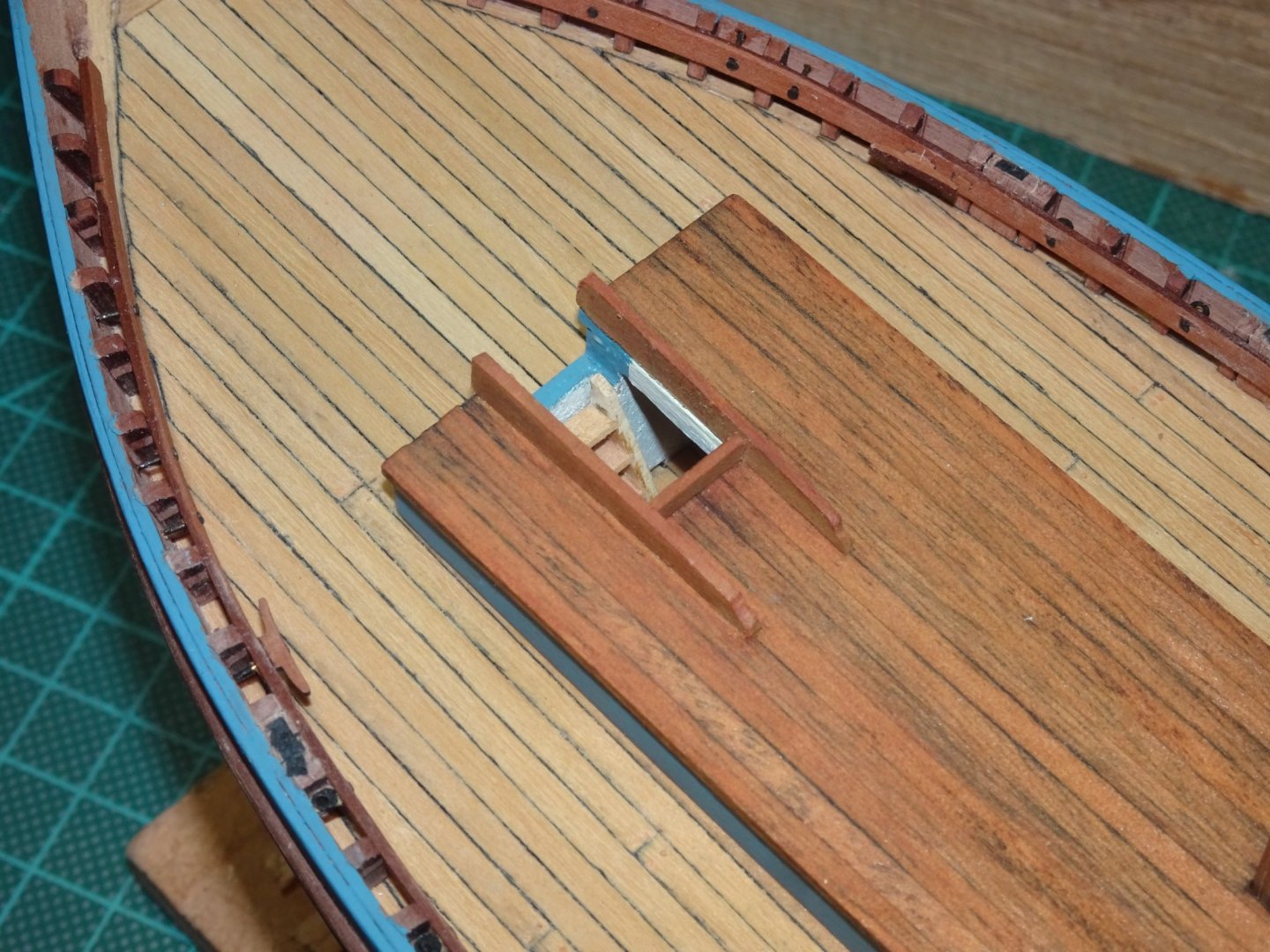
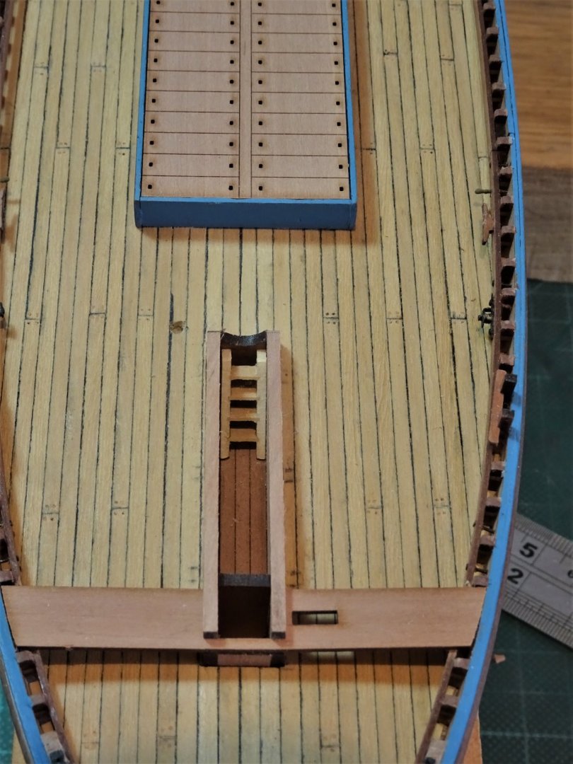
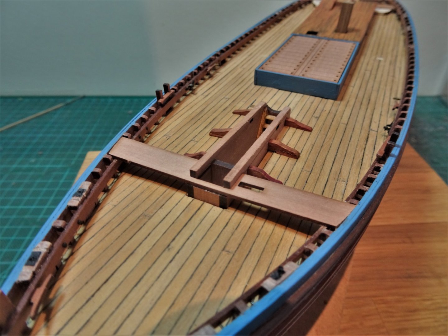
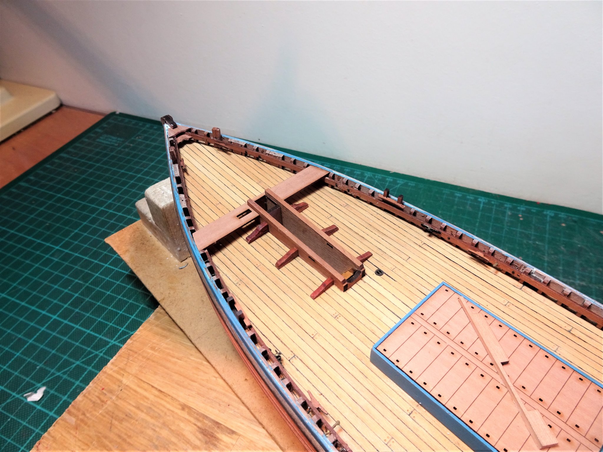
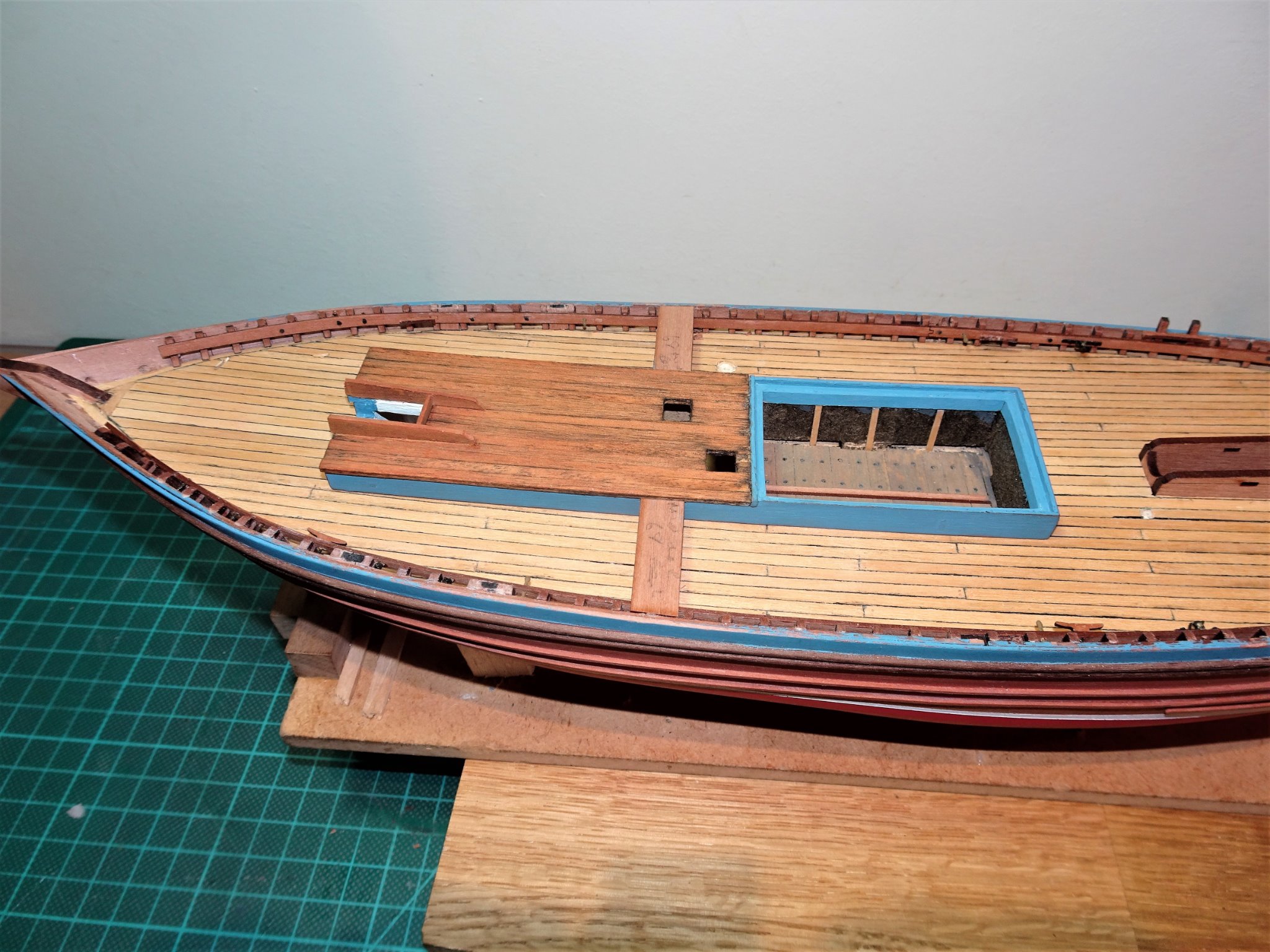
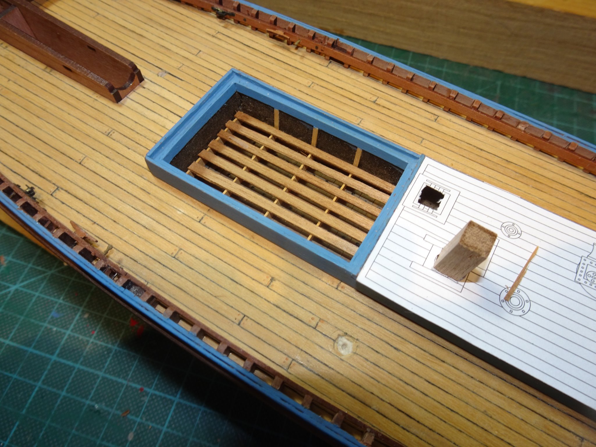
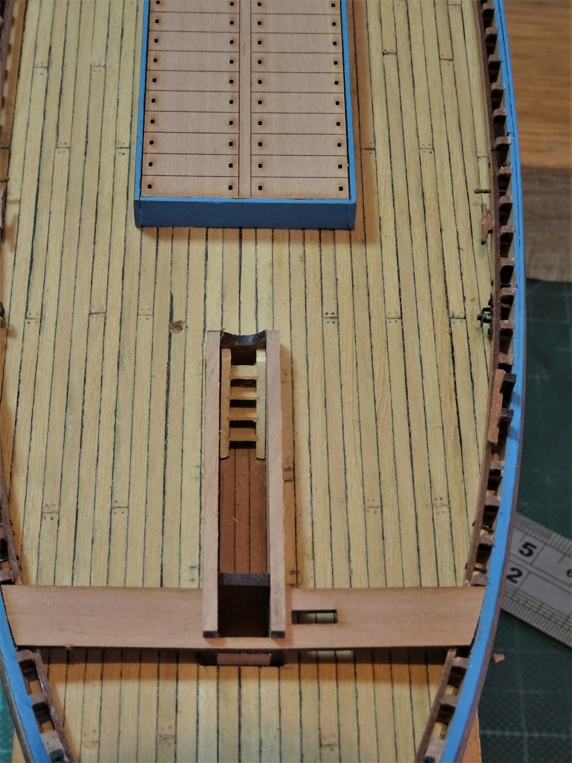
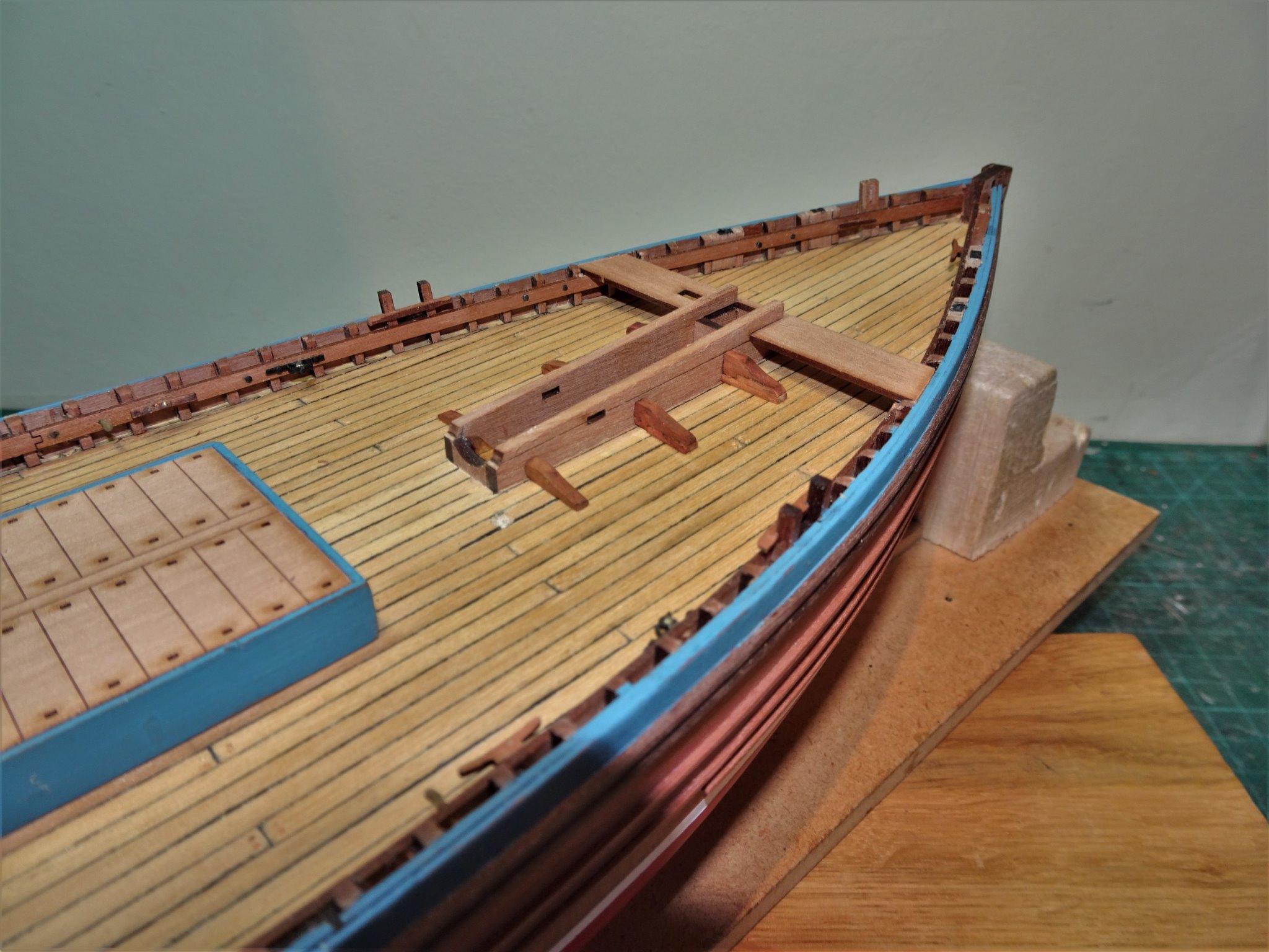
Post 20 Poop Deck and Fore-mast partners. Before these are finally glued into place it is worth test checking the fit of the Fore thwart and Mizen thwarts. These should fit down on the stringers, and back to the bulwark. On my build I had to chisel the timberheads flush with the stringers to achieve this. In reality the thwarts appear to be mortised thro’ the top rail, which is reflected on the plans and the representative models of Muirneag. 7848 On Muirneag the Mizen thwart runs as a straight board, whereas the kit provided version has a flared outboard end. These extensions were removed for the purposes of my build. The kit Fore thwart is a good fit to the mast partners. 7849 The timberheads were cut away above the stringers to allow the thwart to sit fully down. 7852(2) 7850(2) The Poop deck and Fore-mast partners are now glued into place, no issues with fit, and it is a nice touch that Chris provided a decking section below the partners. The 8mm square Foremast fits perfectly between the partners and the mast stop. 7871 I decided to add the Foc’sle ladder which sits just inside the inboard end of the partners. 7870 Even with the mast lowered and resting on the crutch adjacent to the Mizen mast there is still access to the ladderway. The kit has a separate fore hatch which seems a more practicable arrangement and one that is evident on the plans of other Zulu’s. A question mark appears over the number and position of the partner knees on Muirneag. The Underhill plan shows only two each side with a cleat between them. This is reflected on the NMM model, but not the Gordon Williams model which has three. The clincher is that a photo of Muirneag does indeed show three evenly spaced knees. (p288 Sailing Drifters.) but rising in depth as the partners get wider towards the fore part. 7901 Modified knees in place. 7907 The thwart is only trial fitted here. I can now fit out the fish hatch. 7857 Removeable Partition boards used to arrange and distribute the catch in the hold to suit the trim of the boat. 7854 Net platform boards installed. 7855 This is as far as I can take the fish hold detail, and most of this will be covered by the nets. 7860 The companionway ladder can now be fitted. I will next move onto the steering fittings. B.E. 16/10/20

.thumb.JPG.c4e01373deda28f0dbbd49049f5c9829.JPG)
.thumb.JPG.3215b783f0378a351a5037417cbb153d.JPG)


- 261 replies
-
- 11
-
-
- muirneag
- vanguard models
- (and 2 more)
-
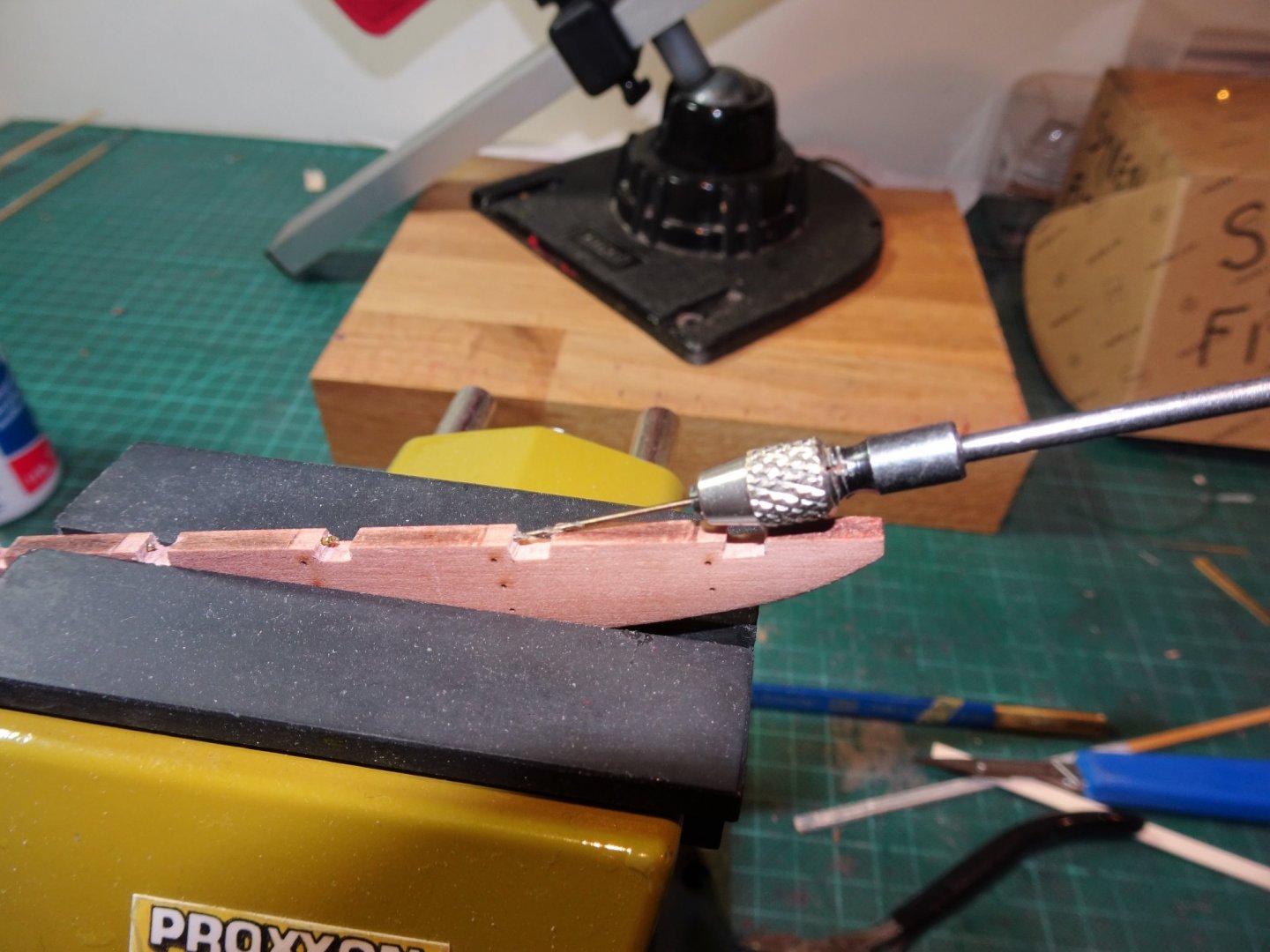
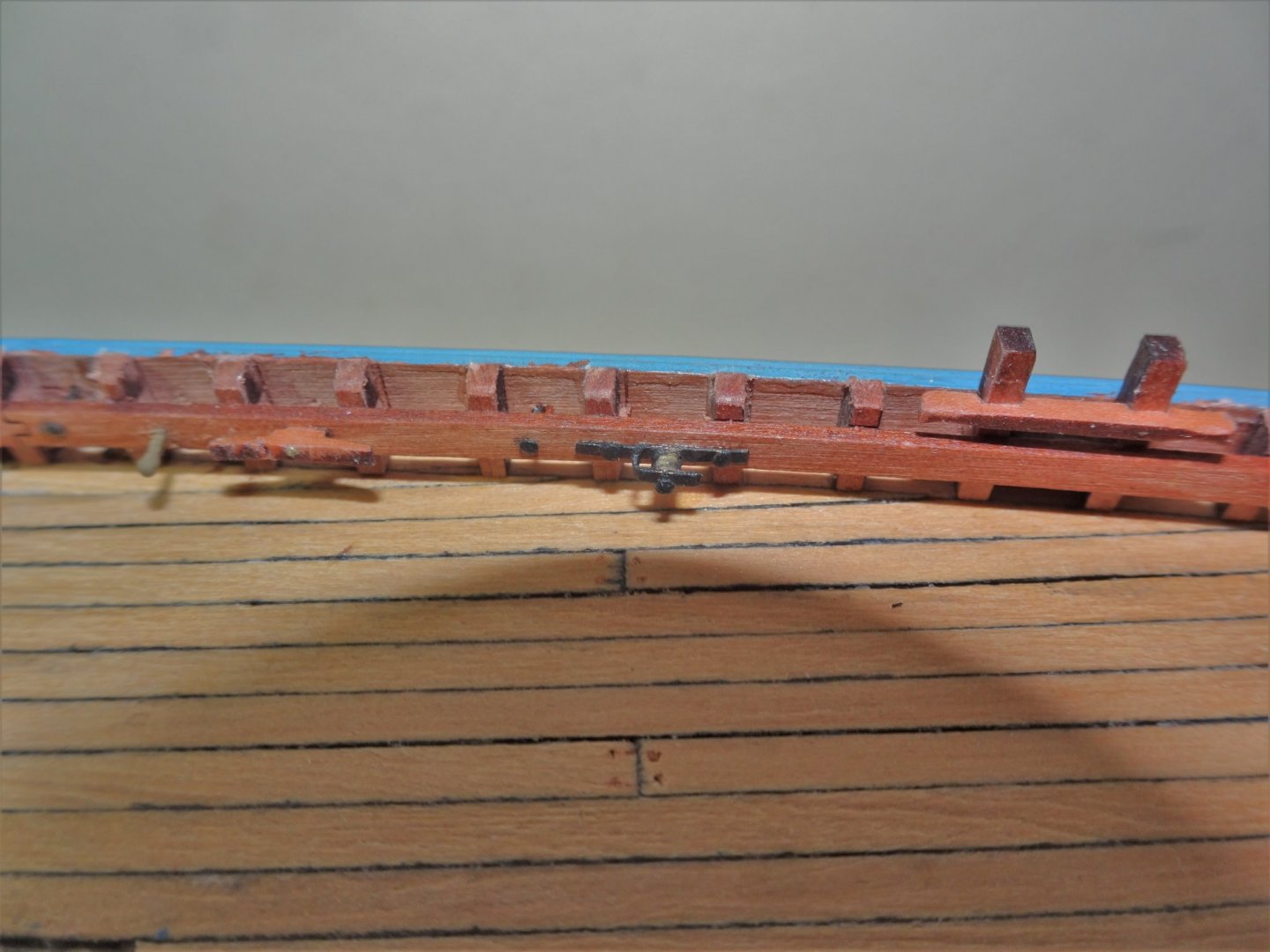
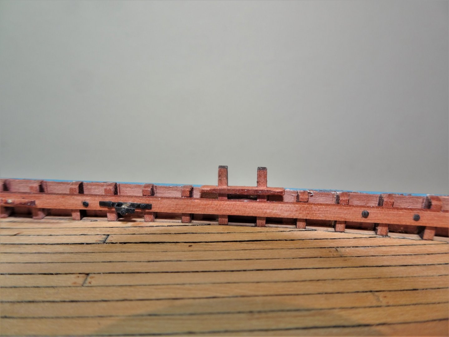
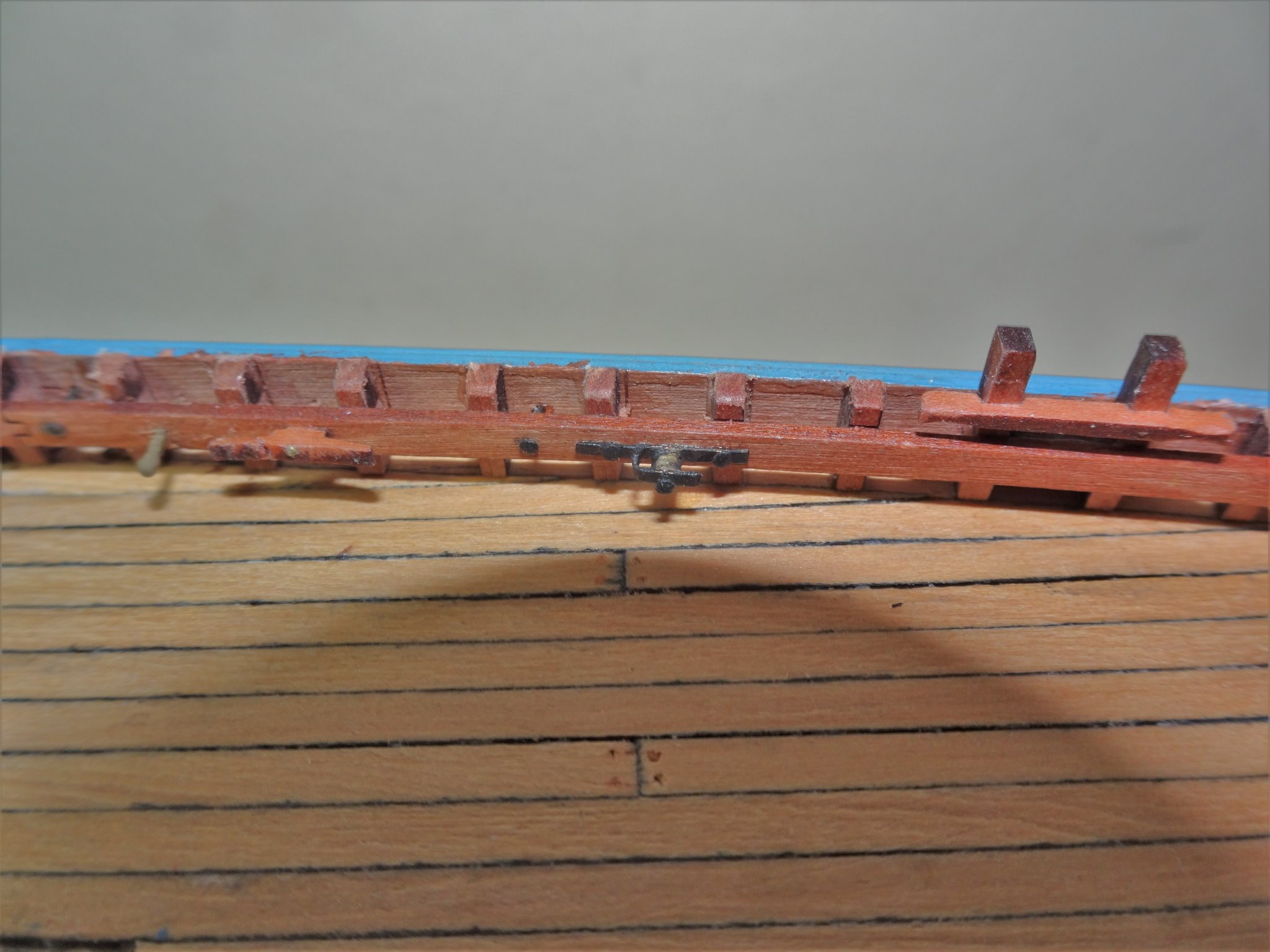
Post 19 Completing the rail fittings All this work is best done before any of the deck fittings are put into place to give best access for drilling holes in the stringers. I have now added the bolts that provide hooking points, and the metal plates to the doublers. 7833(2) Metal bolts thro’ the stringer to provide belay points. Cross pieces have been added to the cavils. The Underhill plans show metal sheaves Port and Starboard for the Fore and Mizen halyards. 7826(2) These are interesting features but I needed to work out an assembly method given their very small size. One of the four belaying pins inserted horizontally through the stringers can be seen aft of the large cleat. For these I used the brass etched versions provided with the Alert kit but enhanced slightly. 7827 The sheave bracket was silver soldered together using thin brass strip, and the sheave is represented by a section of brass tubing. 7833 The completed items are only 9mm long x 1.5mm deep. Most of this stuff wouldn’t be noticed by the casual observer, but it is on the plans, and if I can add it I will. 7845(2) A final repaint of the top rail and I can finally move onto fitting the Poop deck and Fore mast partners. B.E. 14/10/20
.thumb.JPG.16a1ee0eaa116cea2e6ce5438d54e876.JPG)
.thumb.JPG.d115c79ad52c51fe38486128197df172.JPG)
.thumb.JPG.45c0dd606d3edbeded3675eba71780a9.JPG)
- 261 replies
-
- 18
-
-
- muirneag
- vanguard models
- (and 2 more)
-
You're right to be pleased with the stern Glenn, you've made a fine job of it. 👍 B.E.
- 778 replies
-
- 3
-
-
- cheerful
- Syren Ship Model Company
- (and 1 more)
-
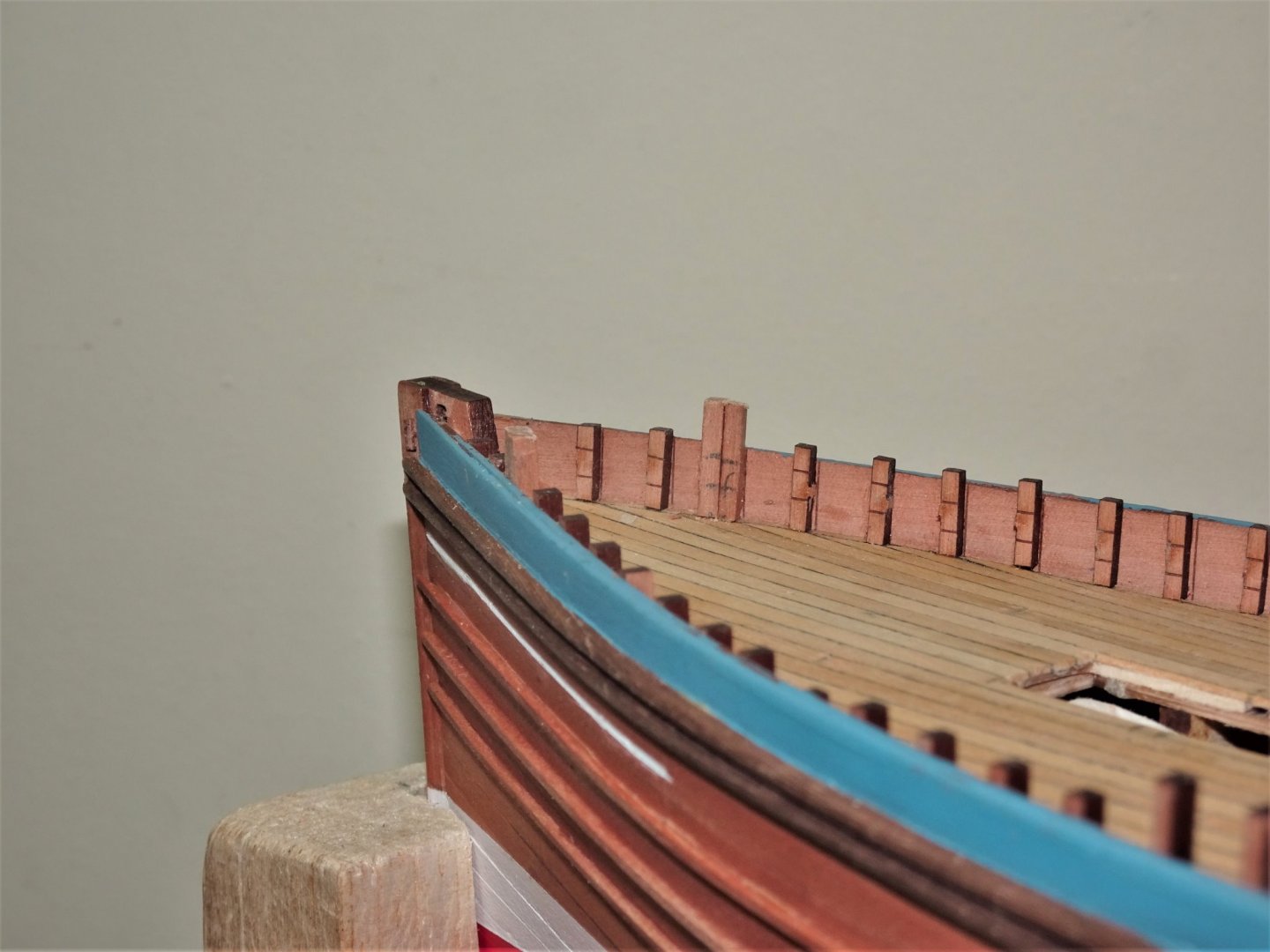
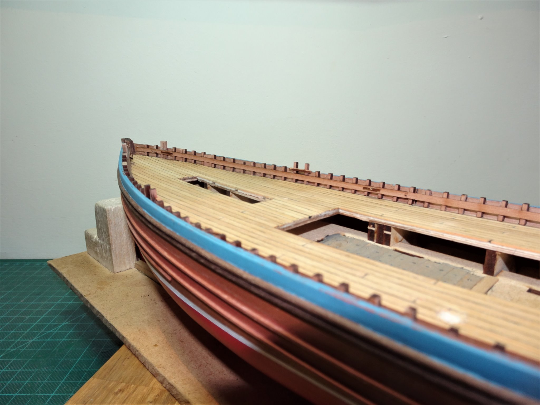
Post 18 Timberheads and stringers. There are 98 tiny laser cut Pearwood timberheads to be glued to the bulwarks, all handed and position specific, so each one has to be removed from the fret and glued individually before removing the next. 7713 A tiresome business, but quite an ingenious method devised by Chris, and one that relieves the builder of the even more tiresome business of individually cutting small sections of square stuff. 7712(2) It is also a nice touch to have the line of the stringers etched into the face of the timberheads. The kit includes the major features along the bulwark, cavils, and cleats, but one slight puzzlement I have is that the cavils, provided as part of the timberhead set, don’t include the cross pieces. This is easily rectified however, using pieces from the fret. The Underhill plans show a wealth of additional fine detail which it is feasible to fit at 1:64 scale. 7715 One immediate modification is the replacement of a single timberhead at the bow with a double timberhead rising above the rail. The Pearwood stringers are attached next having been adjusted for Muirneag specifics. 7733(2) These affect the aft section of the stringers where the morticed positions of the large cleats are filled in, and sockets are added to the back side to take the side light brackets. 7730 With the stringers firmly glued there are a series of infills between the timberheads, called doublers on the plan, these are topped with an iron plate and a socket to take a “ spring warp cage” whatever that is; something else to research. 7729 In this shot the cross pieces have been added to the cavils, and the blocks that form the doublers are in place behind the stringers. 7742(2) The Stringer cleats are now in place but except for the foremost set are repositioned to suit Muirneag. 7739(2) 7740(2) The timberheads now need to be sanded level with the rail and the fittings cleaned up. The final task will be to add a series of bolts through the stringers which act as attachment points for purchases and rigging, and holes drilled to take horizontal belay pins. B.E. 08/10/20
.thumb.JPG.21366cdda9c0f55fe2604fb2141c100b.JPG)
.thumb.JPG.62e5537bab72a9e518f3c4ee92b176d9.JPG)
.thumb.JPG.5958395ab7254a5441a6f692fdfe097d.JPG)
.thumb.JPG.66ac0b65f7466e7afbd4cd38430418cf.JPG)
- 261 replies
-
- 12
-
-
- muirneag
- vanguard models
- (and 2 more)
-
I've had a look at that model Tony, and I see what you mean. It does look a very interesting project and I see that Ancre has a publication out on the vessel. I'm sure you will do the subject justice, I've picked up more that a few tips from your builds. 🙂 Cheers, B.E.
- 261 replies
-
- 2
-
-
- muirneag
- vanguard models
- (and 2 more)
-
Some great stuff comes out of that Chittenango shipyard, and this latest offering is no exception. Beautiful work, Rusty. B.E.
- 642 replies
-
- 4
-
-
- winchelsea
- Syren Ship Model Company
- (and 1 more)
-
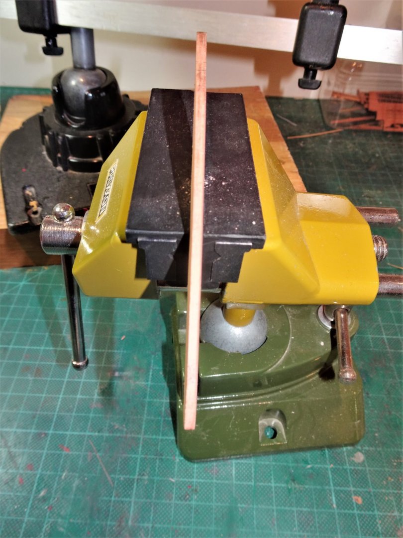
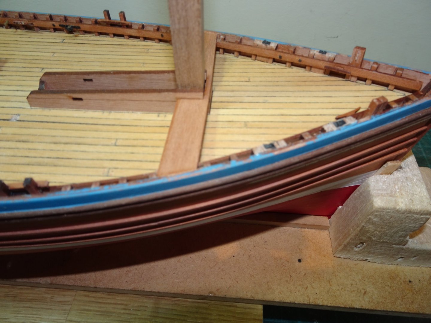
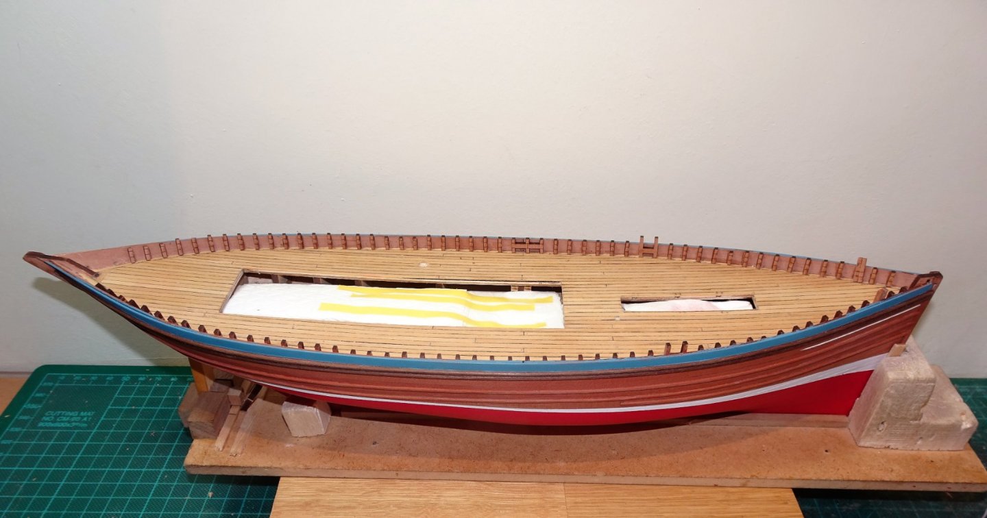
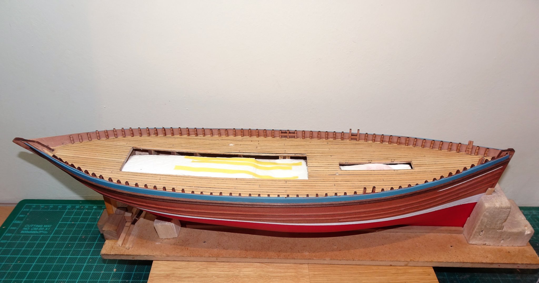
Thank you Yves, Martin and John. I am now at the point where I can relax a little and enjoy the fitting out. @ Martin Rubbing strakes are a pain and it does help to have something on the hull to guide them. She would look quite impressive painted as evidenced from the splendid model by Gordon Williams. He did have the best of both worlds as the Starboard side is unpainted with large sections of the hull unplanked to show interior detail. A point of interest is that a bilge keel is shown which isn’t evident on the Underhill plans but which also is shown on the NMM model (George Macleod) Old photographs would suggest that Bilge keels were a feature of fishing boats of the era. I need to decide whether to retro-fit one. The Zulu is in effect a hybrid design combining features of two of the prominent designs of the time; the Scaffie fishing boat (Sharply raking stern) and the Fifie (which had a straight stem) In any event it became a highly successful design, favoured by many of those engaged in the business of fishing. B.E.
.thumb.jpg.a47b6b9a425dc503484191f0394f33ba.jpg)
- 261 replies
-
- 11
-
-
- muirneag
- vanguard models
- (and 2 more)
-
That looks excellent Erik, I think you're a natural at this planking business. Well done👍 B.E.
- 222 replies
-
- 3
-
-
- First Build
- Lady Isabella
- (and 2 more)
.JPG.43d8dfed6f304a32fe224acdfbf0e283.JPG)
.JPG.54df295a11ddfe11158d8f5abca6f047.JPG)
.JPG.9583781e6be93687cf0eef5a979f0f40.JPG)
.JPG.ca0769e0cb0d8d9198d21aacfc73583b.JPG)
.JPG.6eac8f41d9b7126100693442c8450aa9.JPG)


.JPG.44d8516d151003551c7cea7158f0b5ad.JPG)
.JPG.b71b51734bcaae6ad1789633a4076e7f.JPG)
.JPG.d90639bc9714273265da287a814b7260.JPG)
.JPG.afd97e006f7e9225cda957b3e624aeed.JPG)
.JPG.89dc167c5911df0778056a75aed0154a.JPG)
.JPG.8de4a795b86c5d65c245bb3f103a2a94.JPG)
.JPG.d6cf6acf05dfaf8ee159143487d5bb68.JPG)
.JPG.78c7a70d23971e4755d447bcb2b29550.JPG)
.JPG.17e5283f02758014604c918aa30a640a.JPG)

.JPG.43d4c5ba431db2f1ba99da360b6d8117.JPG)
.JPG.196593ffc755a2cf31196d52f32d6337.JPG)


.JPG.ee54d99902af27cb2e625670b7477407.JPG)
.JPG.0a8c3d223a95cfdddc91e16a6dd6fb98.JPG)

.JPG.91c0b1c24366519f026b98d97bb27cf3.JPG)
.JPG.c9ef3126c4ee245de1db5b73937b8aac.JPG)


.JPG.311671f86d62dc178b9d2b48cebd1106.JPG)
.JPG.072495fbdcae123c05038d0dd6cffd48.JPG)
.JPG.61af7f2b9bf7c02679f64981e757e2a2.JPG)
.jpg.a05a876a5588663a823c1aac713cd53d.jpg)