


gjdale
-
Posts
4,825 -
Joined
-
Last visited
Content Type
Profiles
Forums
Gallery
Events
Posts posted by gjdale
-
-
-
Good to see another Medway Longboat on the blocks. Take your time and enjoy the build - this is a really well designed kit but it does offer a few challenges along the way. You’re off to a great start.
- Ryland Craze and Canute
-
 2
2
-
-
Quite a bit of progress over the last 2 weeks, aided by retirement from 18 Dec!
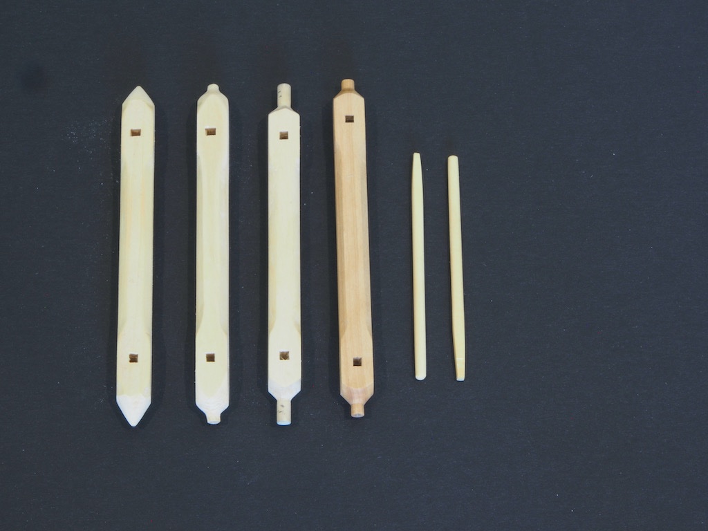
First up, while waiting for paint to dry on the cockpit seats, was the windlass. I ended up having several goes at this. I wasn’t happy with the shape of the ends after my first attempt. On my second attempt, I wasn’t happy with the shape of the square holes (I’d managed to elongate them). On my third attempt, I decided to machine the tenons on the ends. When I placed this inside the boat, it seemed to me that there was too much of a gap between the square section of the windlass and the riser bracket. I compared the windlass template to the plan drawing and noticed that the position of the square holes differed markedly – by about 10mm between centres. In other words, the whole of the square sections on the plan drawings were 5mm further towards the riser bracket than those on the template. I checked in with Chuck on this and his advice was to stick with the template dimensions. Just for the heck of it, I decided to have one more go, this time moving the square sections further out (by about half the actual difference in the drawings). I also decided to do as much of the shaping as possible using a combination of mill and lathe. Since I was going to the trouble of setting up the machines, I took the precaution of preparing two blanks (these were made from some spare 1/2” square boxwood that I had in my stash). I first thinned these down to the 3/8” square using the Byrnes thickness sander. It turned out to be just as well that I prepared two blanks. I was just completing the final machining process on the first blank (turning the final diameter for the tenon) when I took too big a cut and broke the part. Fortunately, I had completed all of the machining processes on both blanks as I went, so it was no big deal to simply complete that last process on the second blank, taking lighter cuts.
The picture below shows the final result. Going from left to right, my first attempt through to the final version, along with the two windlass bars also finally shaped. The fourth (and final) version show the effect of moving the square sections further outboard. I decided I preferred this position. The square holes were achieved by first drilling with a 3/32” drill bit, and then cleaning up with a 3/32” micro chisel (one of my lovely Russian set made by Mikhail).
Next up was the mast ironwork. No issues here – just followed Chuck’s excellent instructions and used JAX Pewter Black for blackening. I did find the belaying pins a bit of a challenge, but again following Chuck’s advice I managed to achieve four reasonably similar results.
The Thole pins were next. Here I departed from Chuck’s suggestion of turning these in the Dremel/rotary tool. Instead, I used my Byrnes draw plate to bring the 3/64” square stock down to a diameter of about 1mm. Following Ryland’s excellent idea from his build log, I made a small jig to position the thole pins a consistent distance from each other within each pair, and also from the edge of the cap rail. The picture below also shows the completed cockpit seats, as well as the three sets of knees on the relevant thwarts.
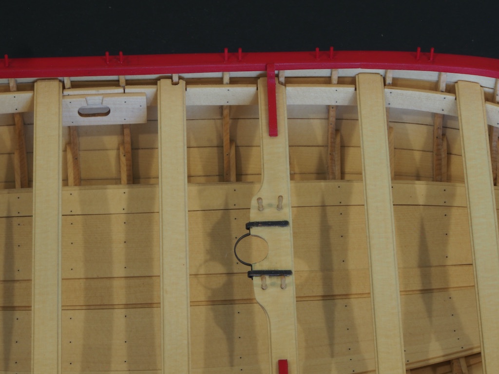
The Fixed Block for the Stem was made up according to the instructions and fitted to the starboard side of the Stem.
And the Roller for the bow was made up and fitted on the port side.
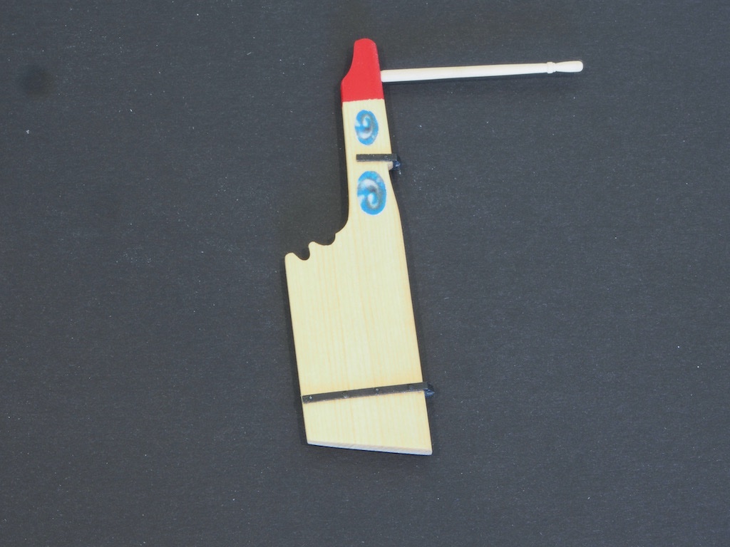
The rudder was next. I first tapered the rudder from forward to aft, per the instructions, and also rounded over the forward edge. The rudder hinges presented no particular problem and were installed per the instructions. Of note here is Chuck’s advice to thin these down once fitted, before adding the wire bolts. Once these were completed, the hinges were painted black, the red section painted at the head of the rudder, and the friezes applied. The tiller was made up from a section of the supplied 3/32” square stock, chucked in the Proxxon rotary handset and shaped with sandpaper and files. A small round tenon was made on the rear of the tiller and a hole drilled in the rudder to accept the tenon.
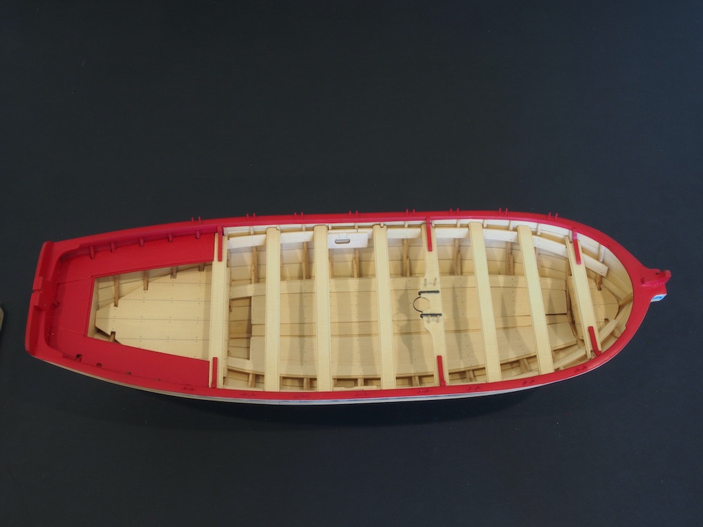
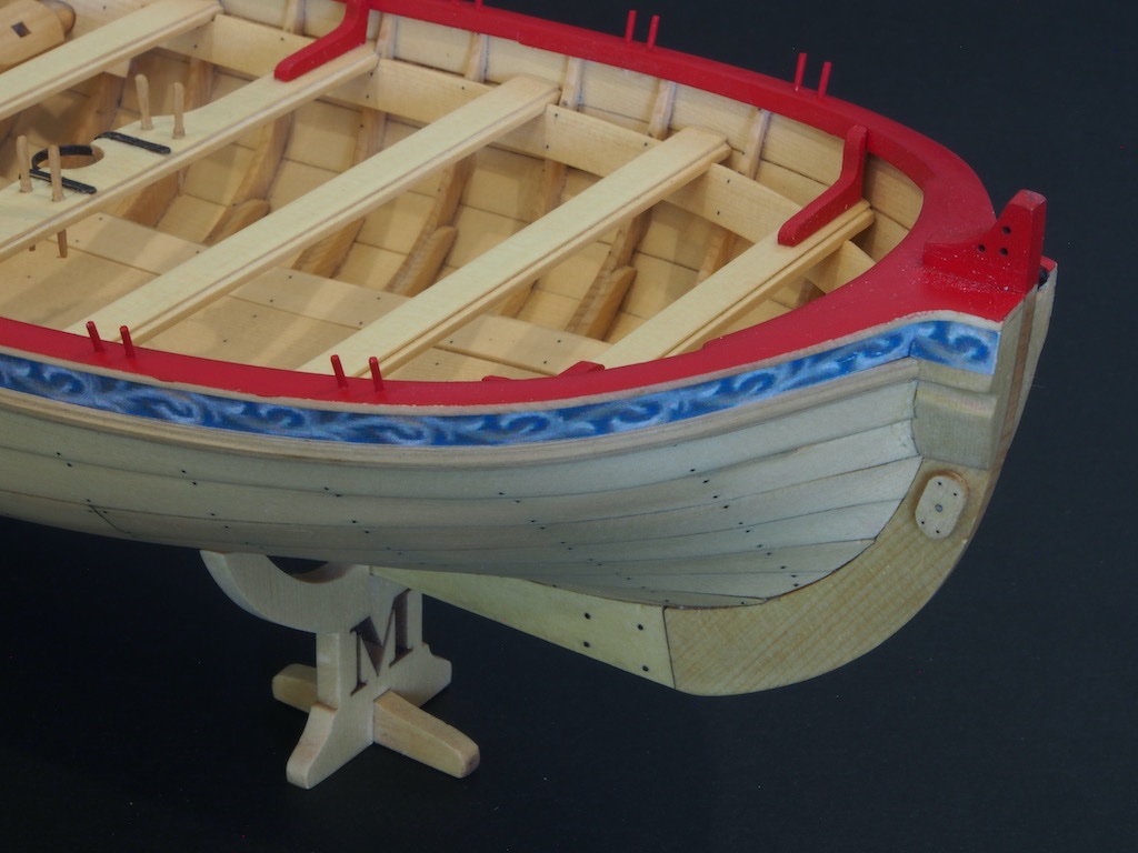
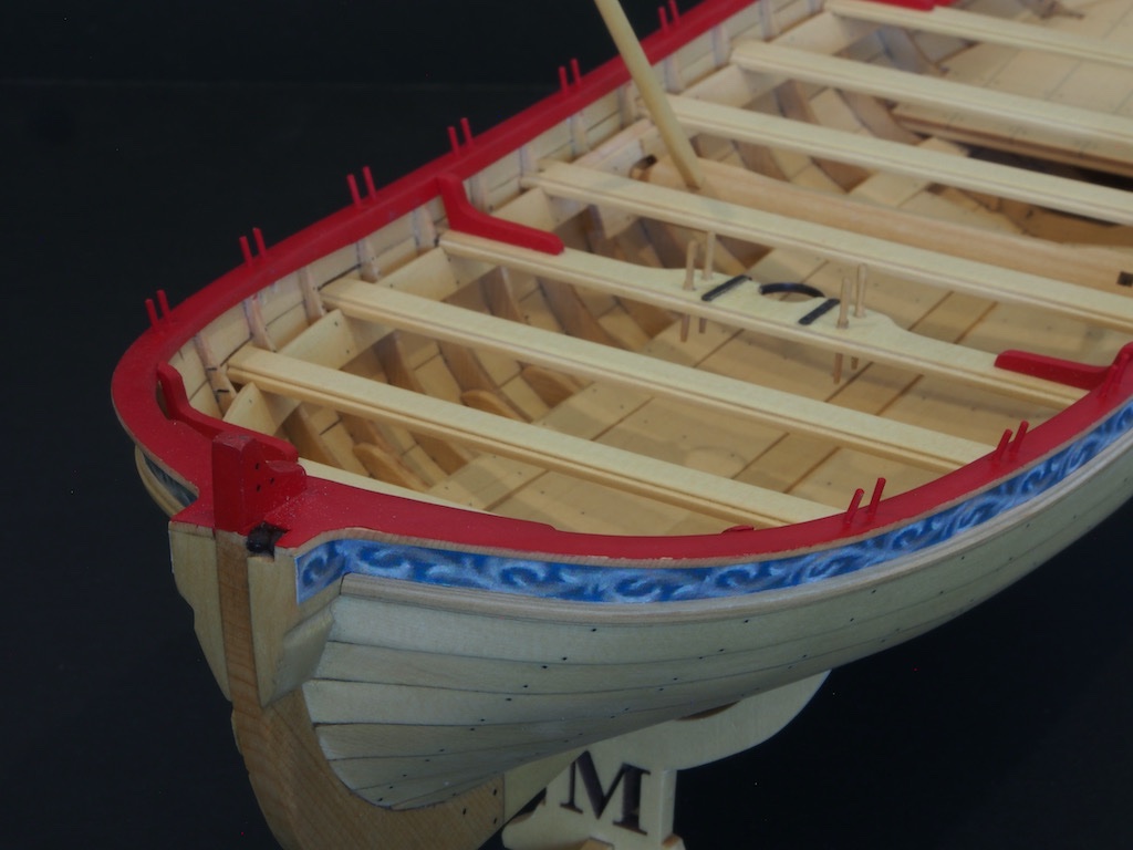
I also decided to take Ryland’s advice and fit the stands to the hull at this stage (actually prior to fitting the thole pins). I’ve also made up the grapnel, although there are no pictures of this yet. Here are a few overview shots showing the completed hull. The rudder has been installed in the photo but has since been removed for safe keeping to avoid damage during the next phase of building.
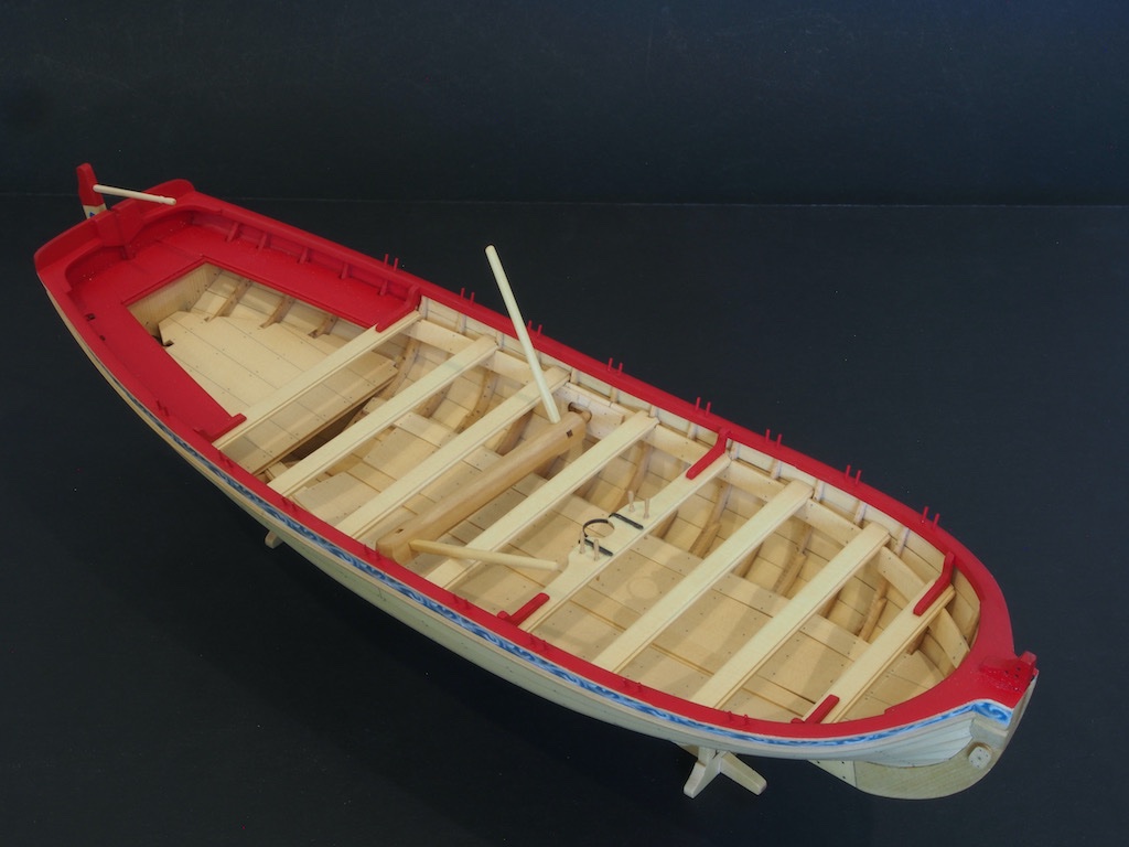
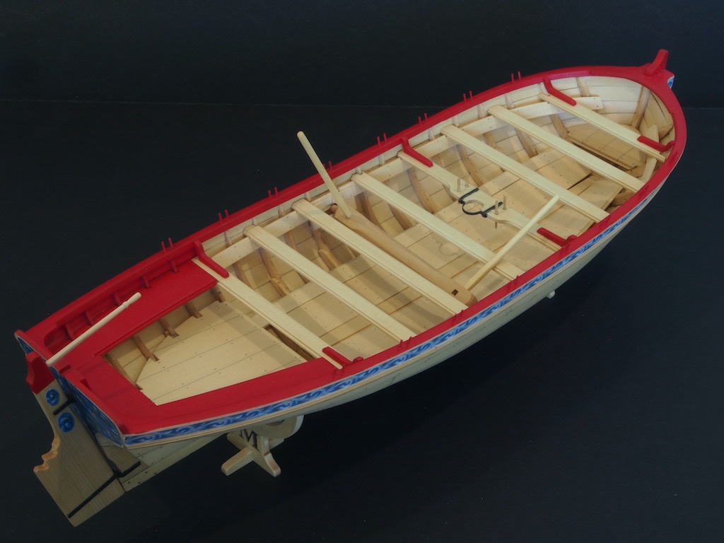
And finally, one with completed hull posed on the display stand.
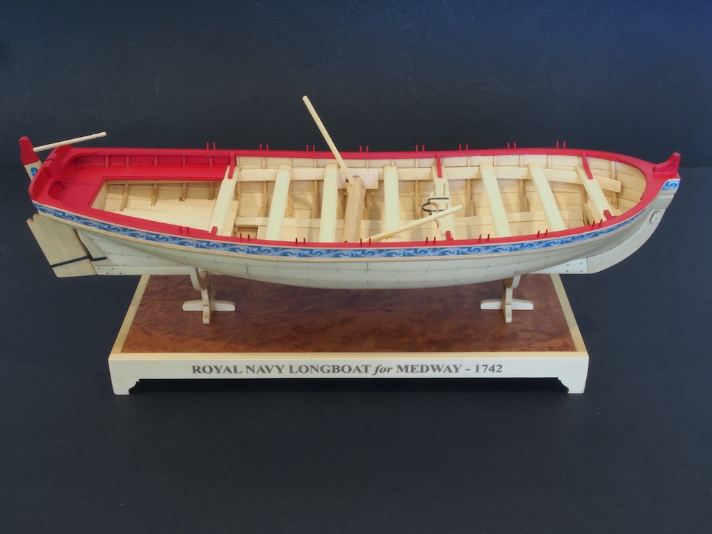
On to the masting and rigging next but will probably have a slight pause while I attend to a 1:1 scale project for a friend….
-
-
Very neat work Dave. She’s looking great.
- Canute, thibaultron and mtaylor
-
3
-
-
-
Sorry to hear that Ken, but good to know that it can be sorted out. The Longboat will be waiting patiently (pun intended) for your return to the modelling desk.
- Canute and Old Collingwood
-
2
-
Nice start. This should build into a very nice model.
-
Nice to see you back Slog and making progress on this interesting build.
- mtaylor and Captain Slog
-
2
-
-
-
Welcome home (to MSW) Remco. Very sorry to hear that life has thrown you a few curve balls, but glad to see you back on the forum. I look forward to the day that progress can resume on your magnificent Kingfisher.
- cog, mtaylor and Ryland Craze
-
3
-
Sorry to hear that Mark - but I think we’ve all done that or something very similar at some point.
A day off and a stiff drink to clear the mind is a good remedy
- mtaylor, FriedClams, Canute and 6 others
-
9
-
Thanks BE - that certainly clarifies things. 😊
-
-
Roger,
Like all of Jim’s tools, the thickness sander is a superbly designed, easy to use tool. I have had one for several years now and have never had an issue of it wanting to tip during use. It may have something to do with the slight upward angle of the feed table. Regardless, I guess the key would be to not try to take too much off in one pass, but you’ll quickly get a feel for what is “about right” for the particular species and thickness you’re using at the time.
Not sure if it’s included with the base package, but there is a separate 6” retainer bar iavailable n addition to the two 3” ones. The two 3” ones allows you to load two different grades of sandpaper onto the machine so you have a “coarse” and a “fine” without having to change paper. If you’ve got slight wider stock, you may want to replace these with the single 6” retainer bar and a single grade of sandpaper. I have found this to be a useful addition.
- Rustyj, Bob Cleek, Roger Pellett and 2 others
-
5
-
-
4 hours ago, Blue Ensign said:
The eye is firstly formed and a short section below soldered
together; the ends are then formed around the block using mini pliers and the bottom ends trimmed to meet
Looking great BE. Are you saying here that you solder the two ends together with the block in place (within the wire)? If so, how do you avoid burning (or disintegrating) the block? Or have I misunderstood you altogether (wouldn’t be the first time!)?
-
Thanks again for the kind comments and likes folks.
Some more small progress:
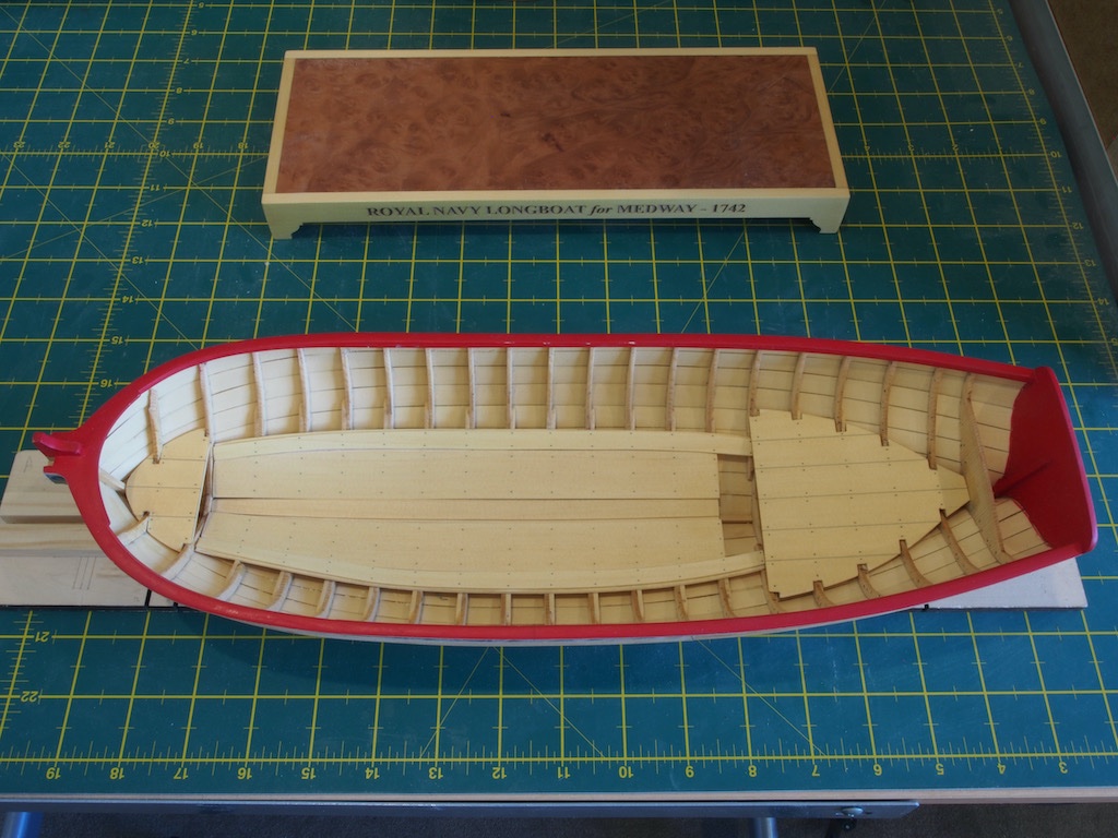
The thwarts have been built and fitted to the model, though not glued in yet. The cockpit seats have also been built, fitted and glued in place. I followed the example of Ryland and others in adding small tabs to the underside of the aft thwart and the aft end of the cockpit seats to provide additional landing places to help keep everything aligned. More work to do yet on the thwarts, and lots of painting in the cockpit…
- bruce d, BobG, Ryland Craze and 7 others
-
10
-
Slow progress, but progress nonetheless. I have completed preparing and installing the risers. Using the heat/hair-dryer method to pre-bend the risers makes attaching them much easier. I picked up a tip from a couple of other logs about using a small T-square jig to position the risers at the correct height at each frame. Rusty’s log is a good demonstration of this jig and its use, so I’ll not repeat it here. The method is also described and demonstrated quite nicely in the Queen Anne Barge instructions. Note for Chuck – it might be worth copying and pasting that section into the Longboat instruction manual next time you revise it. It’s a great tip/trick and worth repeating in both instruction manuals.
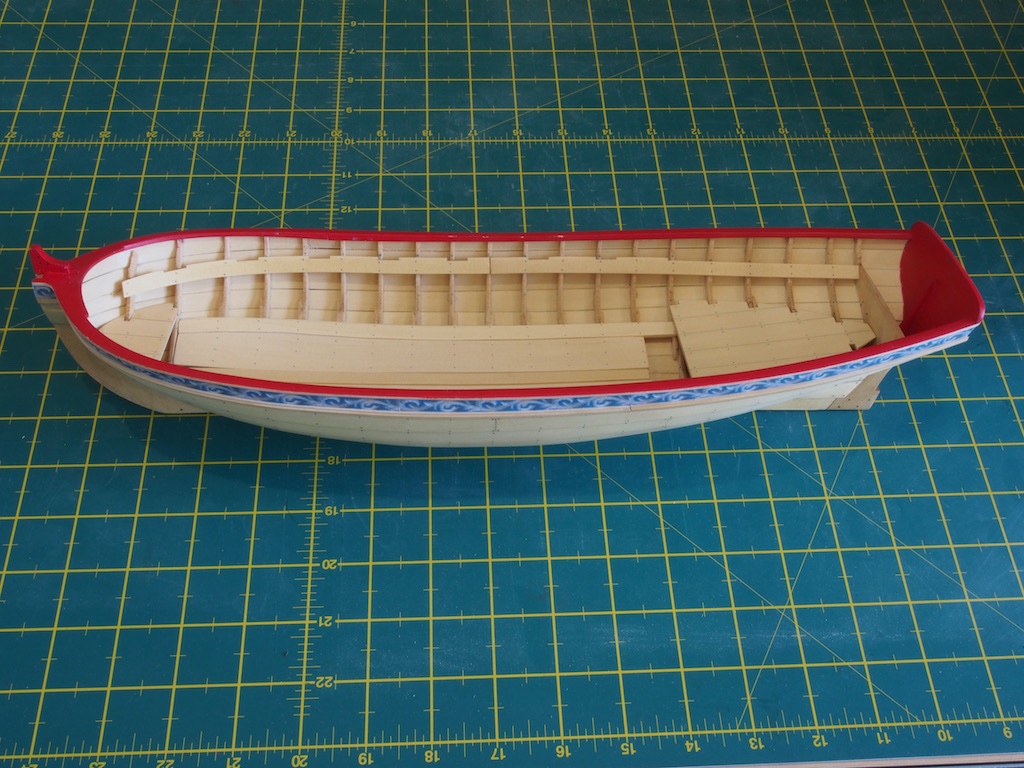
Onto the thwarts next...
-
-
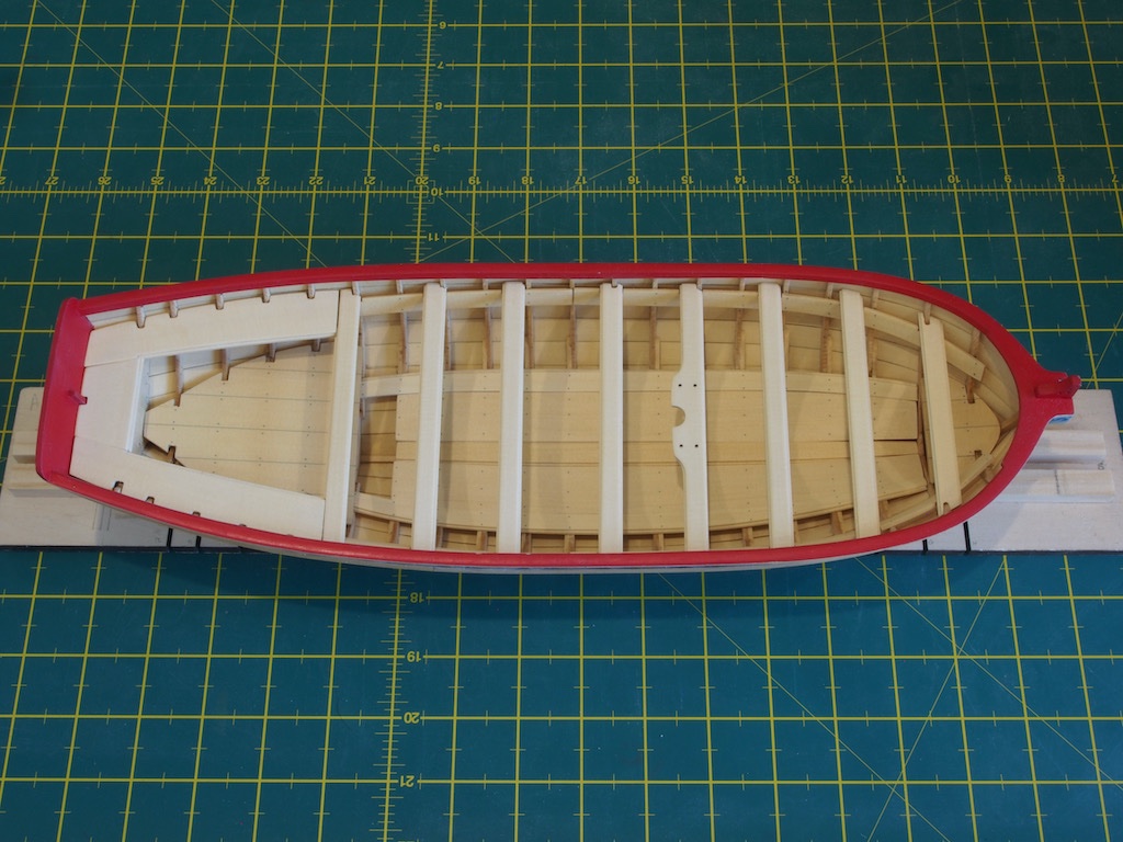
Thanks for all the kind comments and also for the "likes".
Progress seems to have been slow of late, but I have completed the floorboards and platforms. The only problem I ran into with the floorboards was that when I went to fit the outer floorboards, I somehow got them mixed up and fitted them to the wrong sides, requiring quite a lot of additional shaping that resulted in quite narrow extensions at the aft end. Fortunately, I realised my mistake before gluing them. I was then able to re-cut these parts from some spare kit material, using the original laser cut sheet as a template.
The platforms were a little tricky to fit, and the bow platform required significant shaping to fit. All “nailing” was done off the model prior to fitting of both floorboards and platforms.
Unfortunately, the cap rail took a little bit of scuffing during all of this and will require some touch up. I’ll wait until I’ve installed the risers before doing that.
Progress shot of the internals.

Medway Longboat (1742) by gjdale - FINISHED - 1:24
in Medway Long Boat - 1742 - Public group project.
Posted · Edited by gjdale
Thanks very much for the kind comments guys. And yes Chuck, I have enjoyed this kit very much - it’s such a pleasure to work with a kit that has been so thoroughly well thought out and with such clear instructions on HOW to go about things while still allowing some room for individual preference. I still think my planking could have been a lot better, but that is on me and I’m sure I’ll take those lessons on to the next build.
And Rusty, I’m sure Glenn did a fine job too....😉😎😁...