


gjdale
-
Posts
4,825 -
Joined
-
Last visited
Content Type
Profiles
Forums
Gallery
Events
Posts posted by gjdale
-
-
As long as they are sanded flush, they shouldn’t be a problem as you will be sealing them. If oxygen can’t get to them, they can’t rust.
- thibaultron, mtaylor and lmagna
-
 3
3
-
Kevin,
I would think that the solution to that particular issue is to stop posting on the FB group, rather than stopping work on your model. Come back to it after AV and post your progress here. In all the time I’ve been a member here at MSW I don’t think I have ever seen that type of “trollish” behaviour - only ever encouragement, support and constructive suggestions.
- EJ_L, Beef Wellington, Haliburton and 7 others
-
8
-
 2
2
-
I’ve only just stumbled across this outstanding build log Gary and all I can say is WOW!!! What a superb piece of modelling. Thank you for your detailed explanations of your processes too.
- Edwardkenway, Jack12477, Keith Black and 7 others
-
9
-
1
-
Good question Popeye. The instructions call for both medium CA and 5 min Epoxy (as well as wood glue for the wood bits). I’m open to suggestions in this regard as I have very little experience with Britannia metal castings.
- Canute, popeye the sailor, Egilman and 2 others
-
5
-
This looks fascinating - I’m in!
- popeye the sailor, lmagna, Kevin and 5 others
-
8
-
Good to hear that progress is being made Mobbsie, but……if there’s no pictures, it didn’t happen….😉😎
-
Thank you one and all for the very kind comments and likes on the completion of my Longboat model.
Unfortunately, as I was setting up to take some "what's in the box?" photos for my new build, I knocked the camera and tripod over onto the Longboat. By a stroke of good luck, damage was minimal and relatively easily repaired - a little glue, a lick of touch up paint, and some re-tensioning of the rigging and all is good. No photos of before and after but rest assured all has been put to right. Just need to find a safer temporary place for the longboat until her permanent home is decided.
- Ryland Craze, Chuck and a49kid
-
3
-
Thanks for all the interest folks. I hope to make a start in the next few days. There may be a slight delay while I make some minor repairs to my Medway Longboat. While I was setting up the photos for this log, I knocked over the camera and tripod - right onto the longboat! Fortunately, damage was minor and won’t take much to fix.
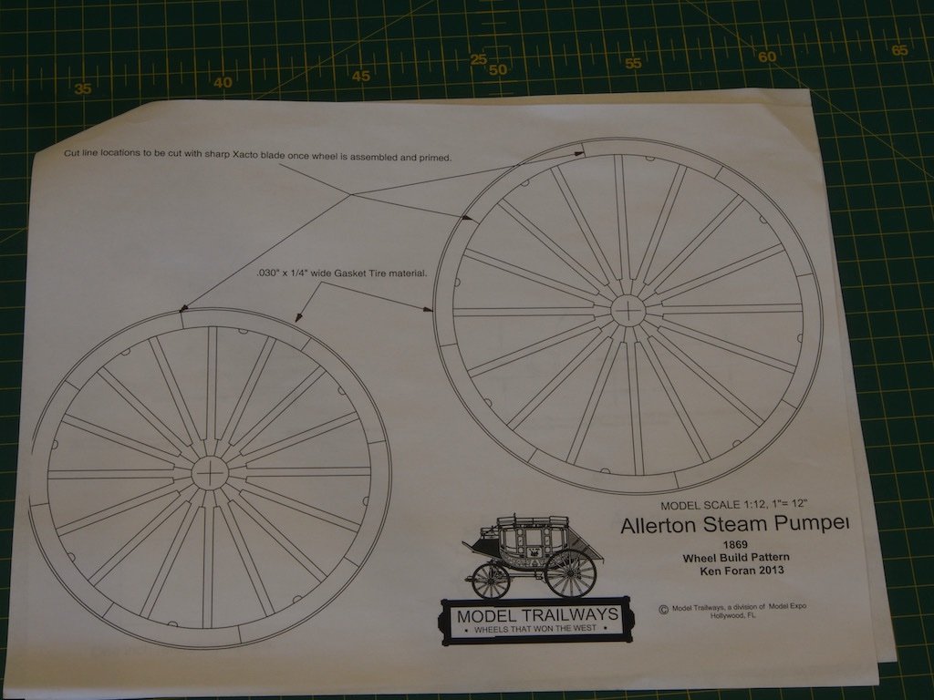
Ken - there is no jig for the wheels, only template patterns. The wheels are an interesting part of the construction in their own right. It’ll be a while before I get to that stage though.
- thibaultron, mtaylor, FriedClams and 5 others
-
5
-
 3
3
-
Introduction
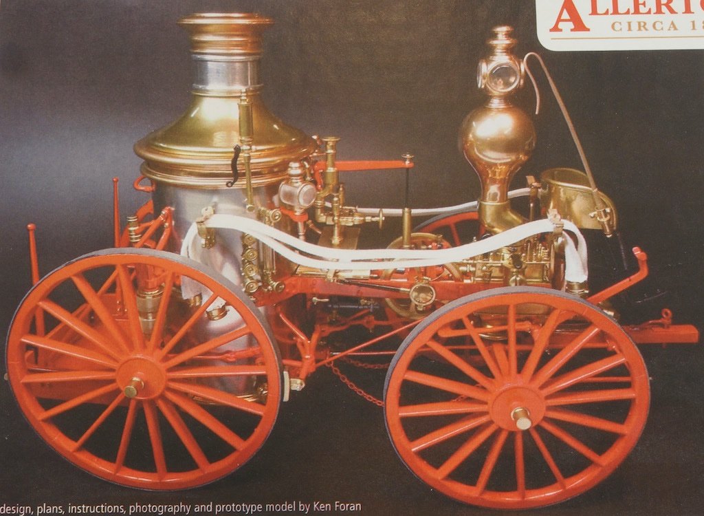
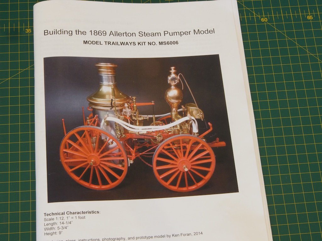
Anyone who has followed my builds will know that I have a fairly eclectic taste in models, and this is no exception. I bought this kit on a whim one day several years ago when Model Expo were having one of their frequent sales. I thought it would make a very attractive addition to my model collection, and my wife liked it too, so what was I to do? This model was designed by Ken Foran (a well-known member of MSW), who also did the plans, instructions and prototype model. In addition to being a member of the MSW forum, Ken has also published the book Model Building in Brass, which is a must have coffee table and go-to reference book. Ken’s work is truly outstanding, and I only hope that I can do his gorgeous design justice.
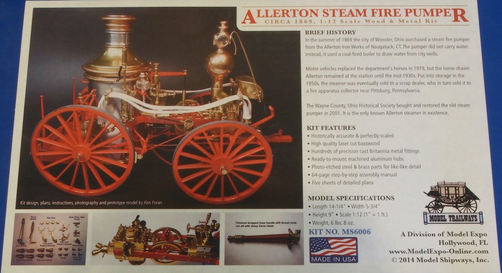
Rather than re-type the history of the Allerton Steam Pumper, I have included a photo of the box lid, which tells the story. The model is in 1:12 scale (1” = 1 ft) and the completed model measures 14 ¼” (362mm) long x 5 ¾” (146mm) wide x 9” (228mm) tall.
What’s in the box?
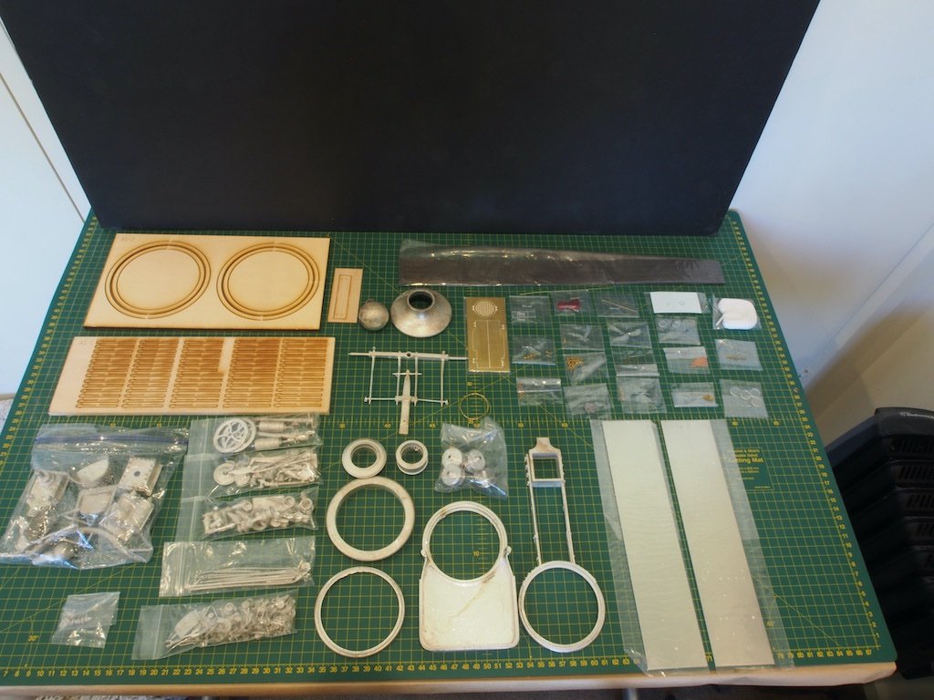
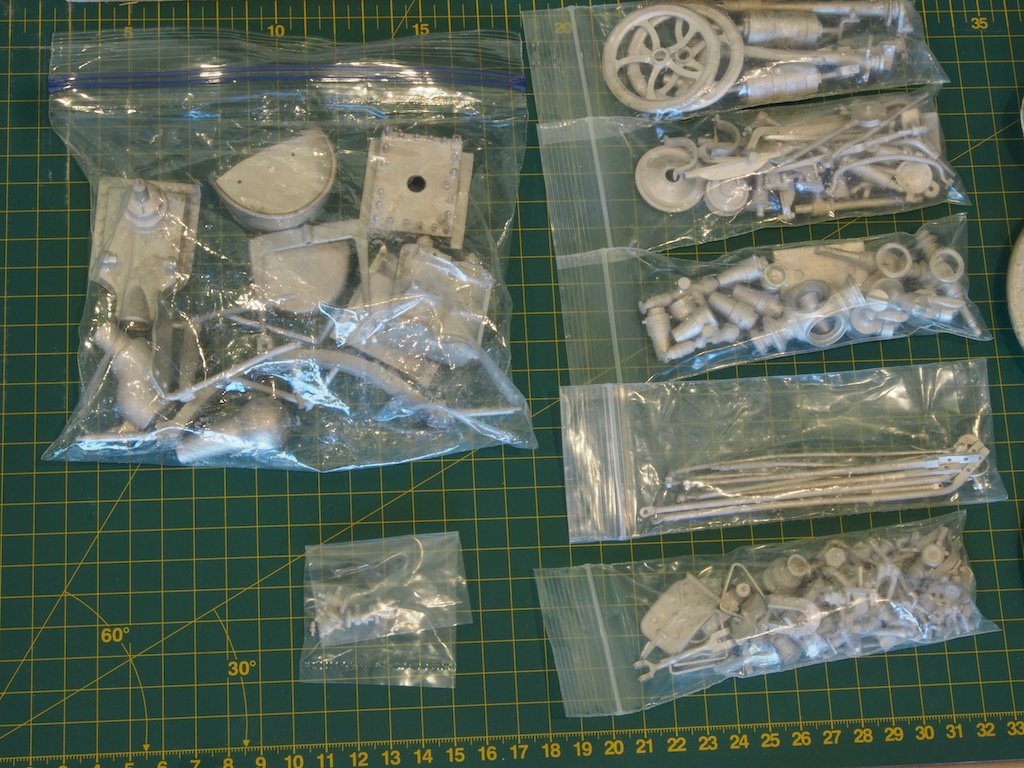
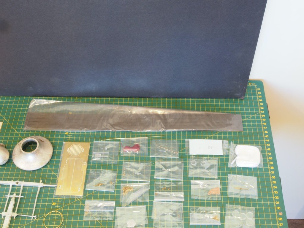
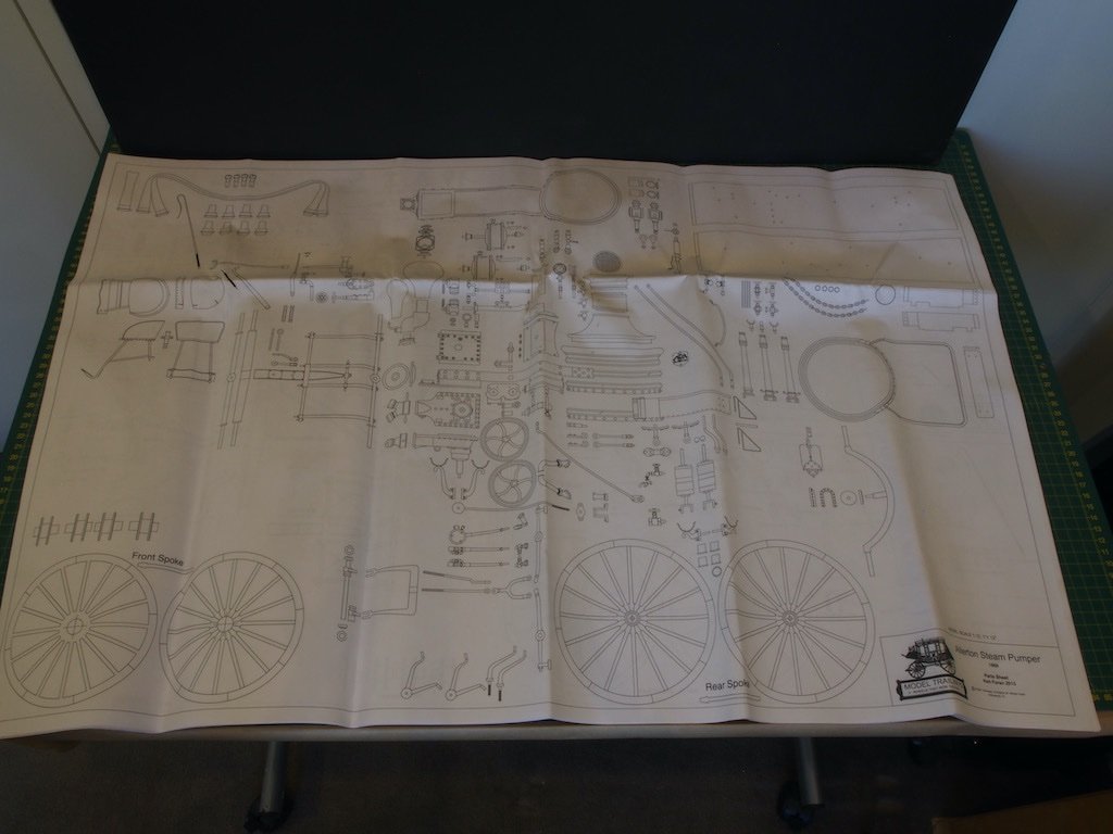
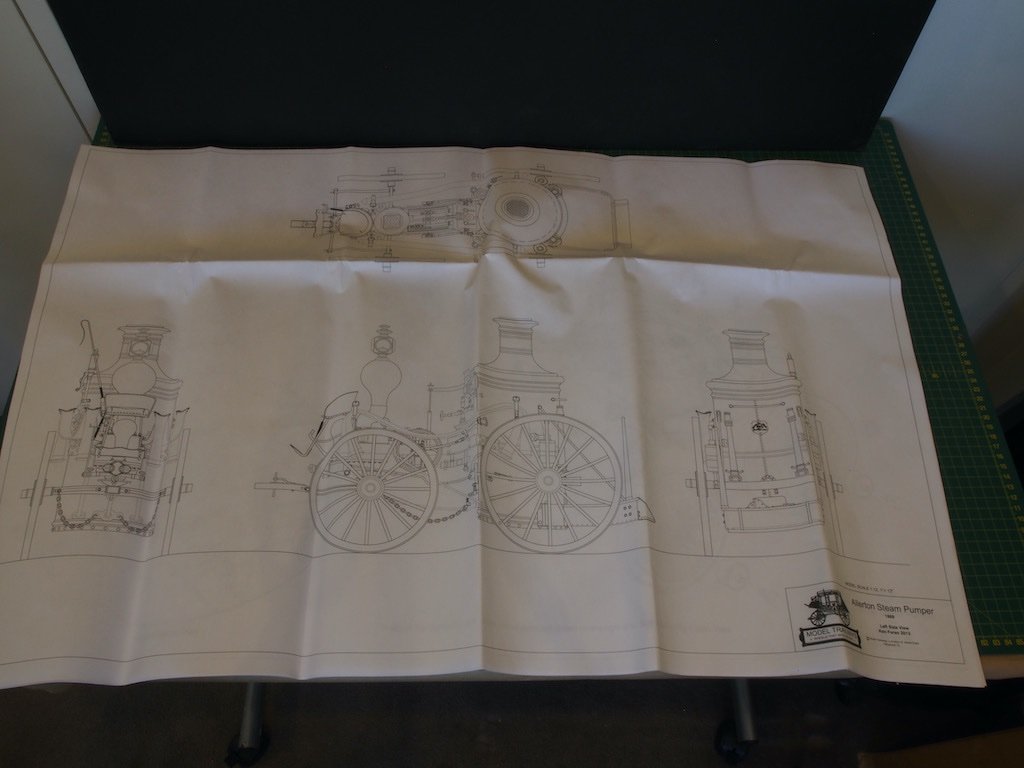
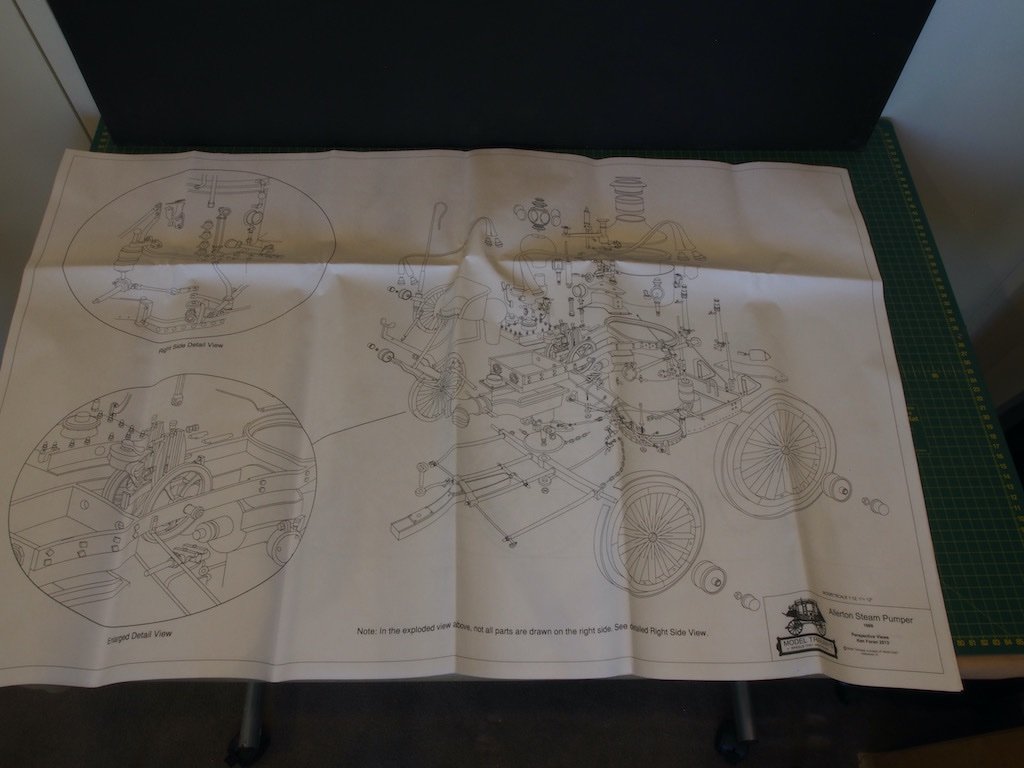
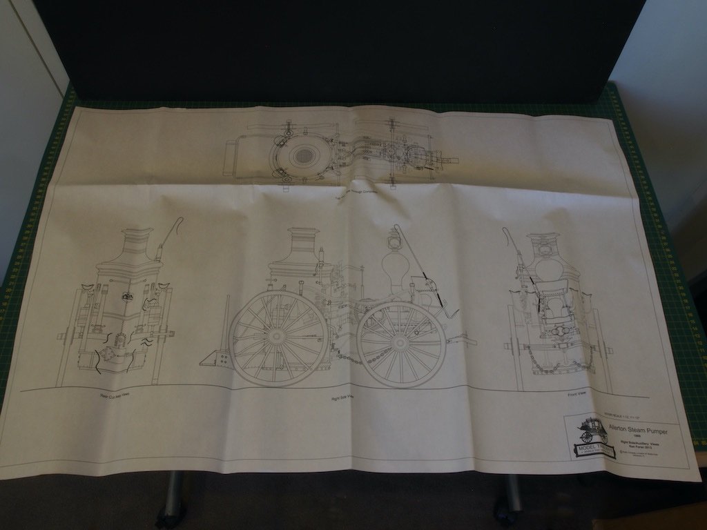
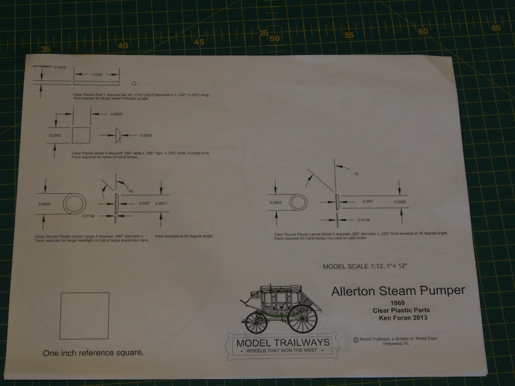
The kit contents are interesting in that there is very little wood at all. What wood there is, is laser cut basswood and appears to be of decent quality. There is a plethora of cast Britannia metal fittings, some nicely machined aluminium hubs and a number of photo-etched steel and brass parts. With all of that metal in the build, the finished model weighs in at a hefty 6lbs 8oz (just shy of 3kg). The instruction manual is 64 pages long and includes quite a number of colour photos to support the detailed instructions. At first reading, this manual is a considerable step above the typical kit offerings. Also included is a set of 5 large pages of plans and drawings as well as two further pages giving details of clear plastic parts and wheel templates.
Here is an overview of the box contents (minus plans):
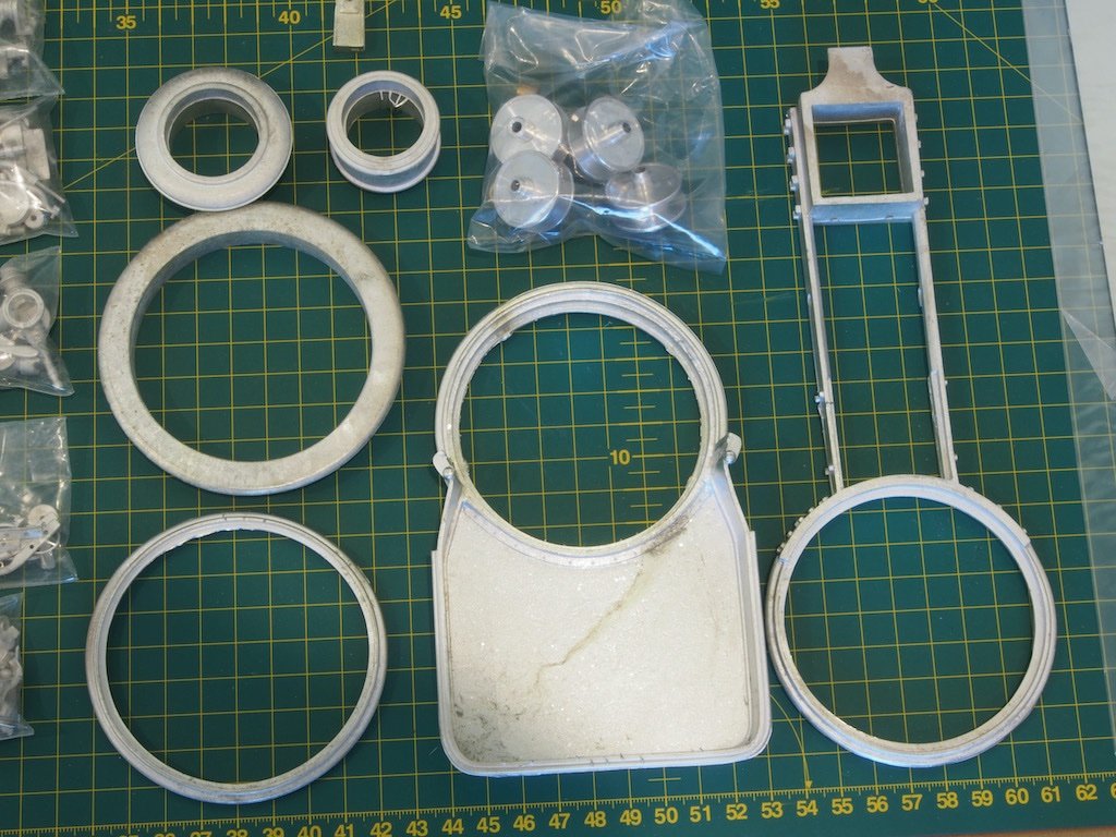
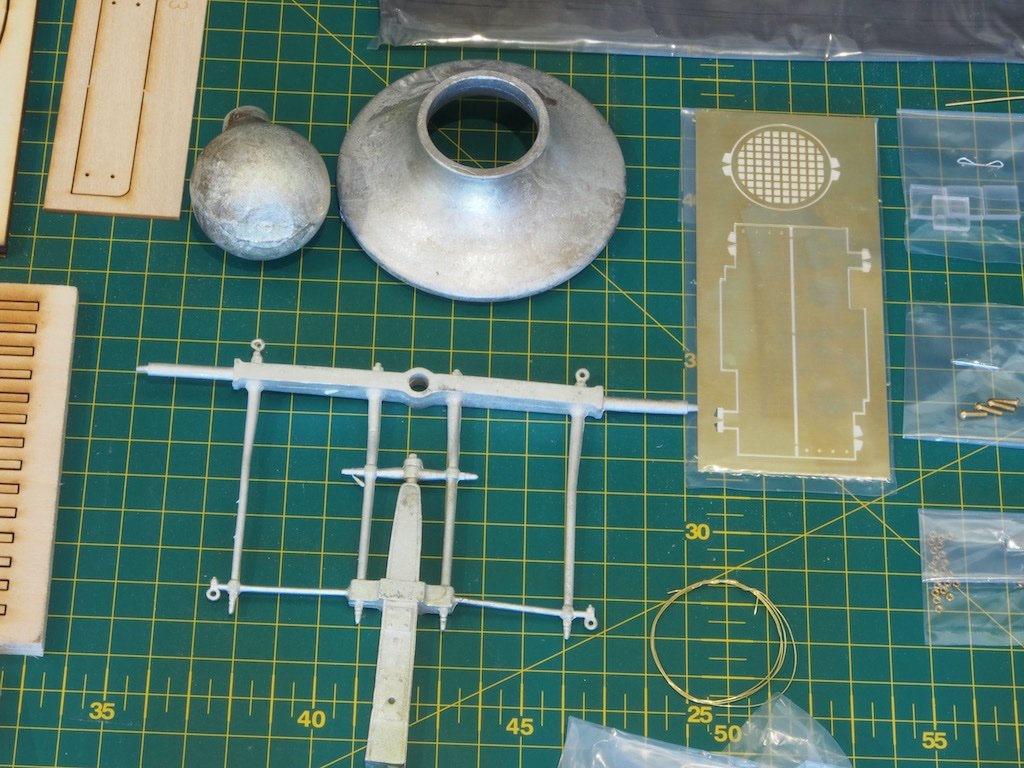
And here a few close ups of the various component groups.
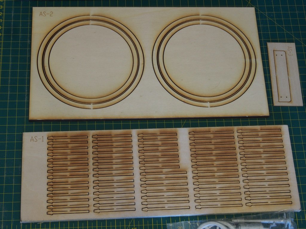
The only wooden parts – the wheels and their spokes:
Several bags of Britannia metal parts:
More cast metal parts and the machined aluminium hubs:
More cast metal parts and some brass photo-etch:
Some photoetched stainless steel parts:
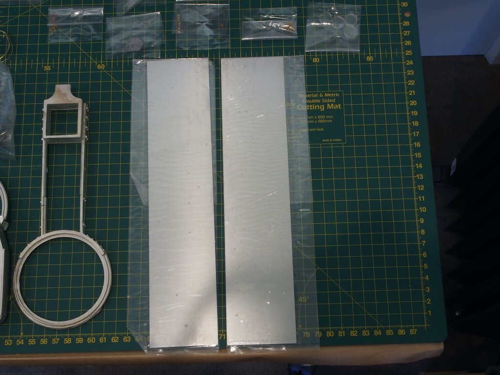
A range of small parts:
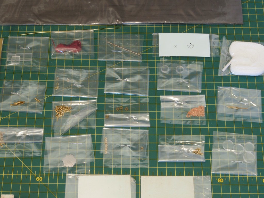
More small parts and the wheel tyres in the long packet at the rear:
The plans sheets:
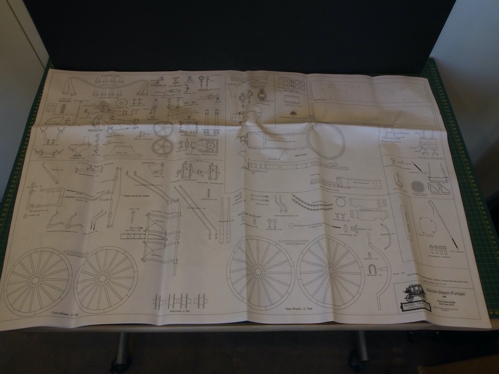
And the additional drawings:
And finally, the instruction manual:
I'll be back when construction begins in earnest.....
- Rik Thistle, wefalck, mtaylor and 17 others
-
20
-
Riotvan88,
I was faced with a “never done this before” situation with my Chris Craft runabout. A detailed explanation of trials and then the actual process can be found in my build log here starting on page 5 at post 145 for the trials and page 6 post 153 for the actual process. I was guided a lot by a tutorial I found on the RC Groups forum.
-
Hey Jeff,
So great to see you posting a build here! I have some very fond memories of my interactions with you when you were running Hobby Mill and I still have a lifetime’s supply of your excellent product for all of the projects on my bucket list.
Your build is looking excellent so far and I’ll enjoy following along the rest of the journey.
- BobG, Boatsinc2000 and mtaylor
-
3
-
Just caught up with your build Bob. What a fantastic job you are doing too! She is looking truly spectacular.
-
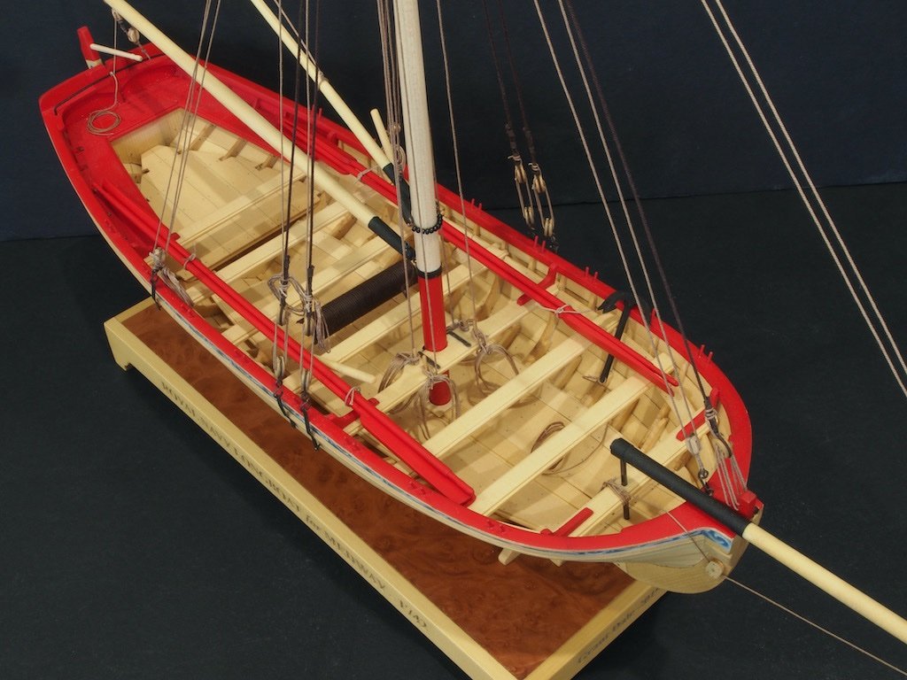
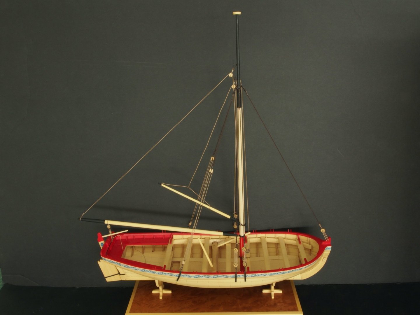
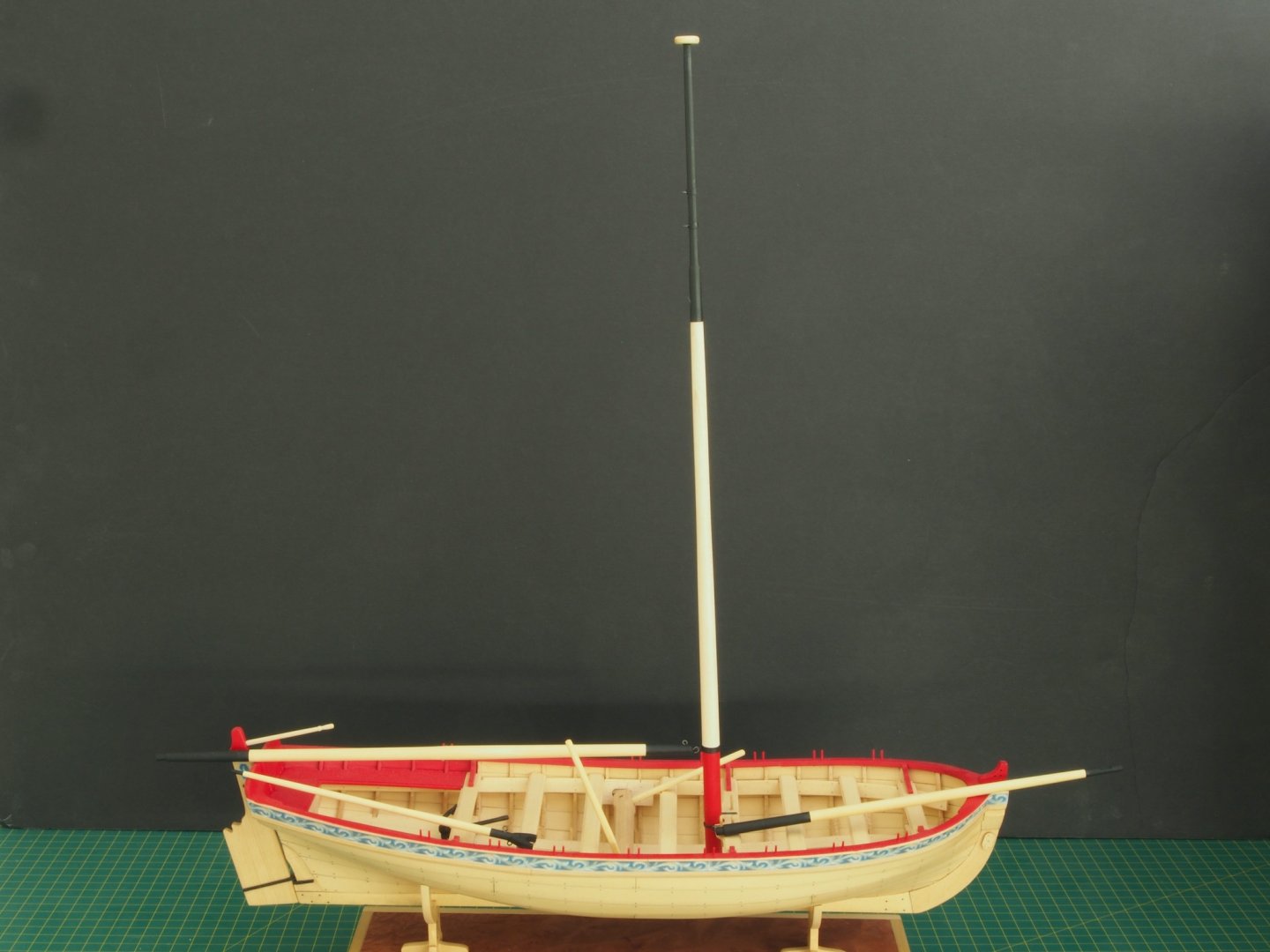
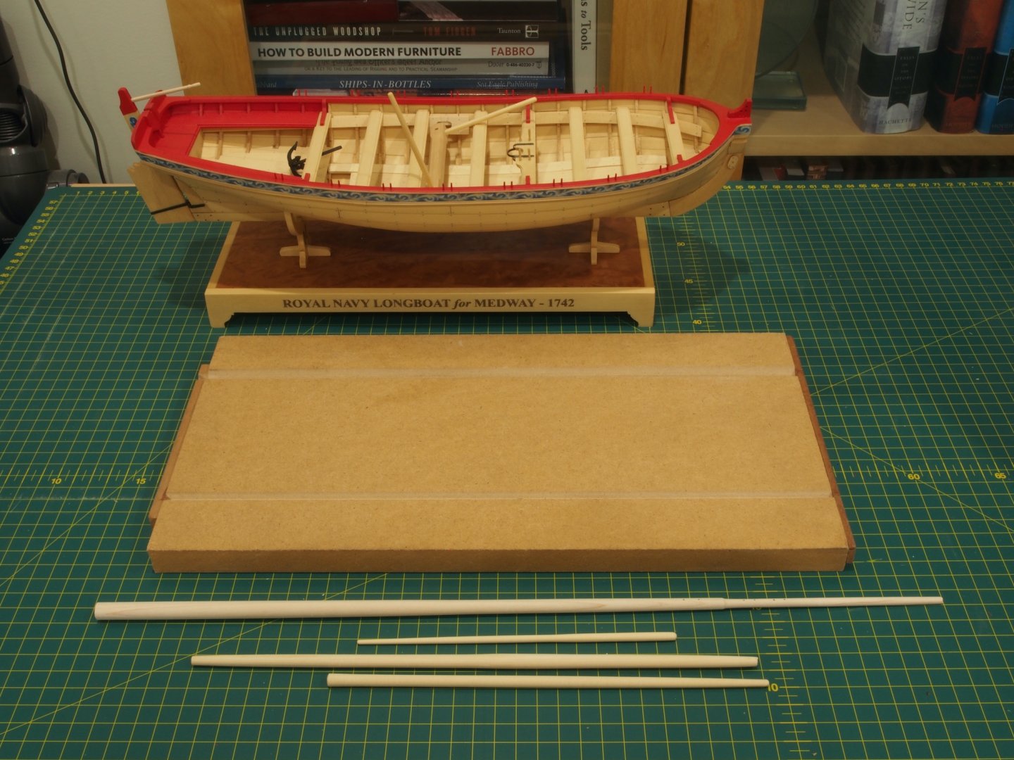
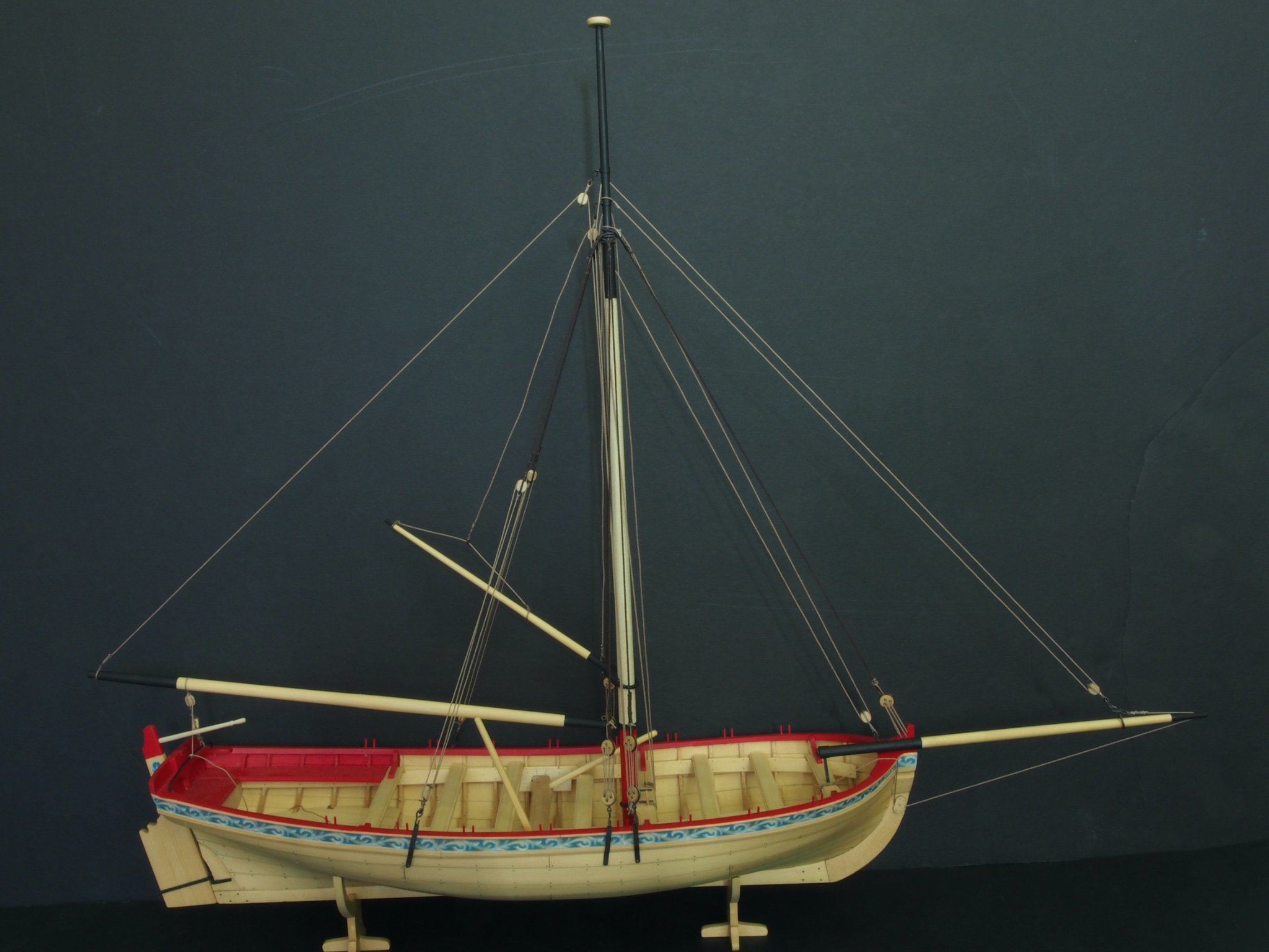
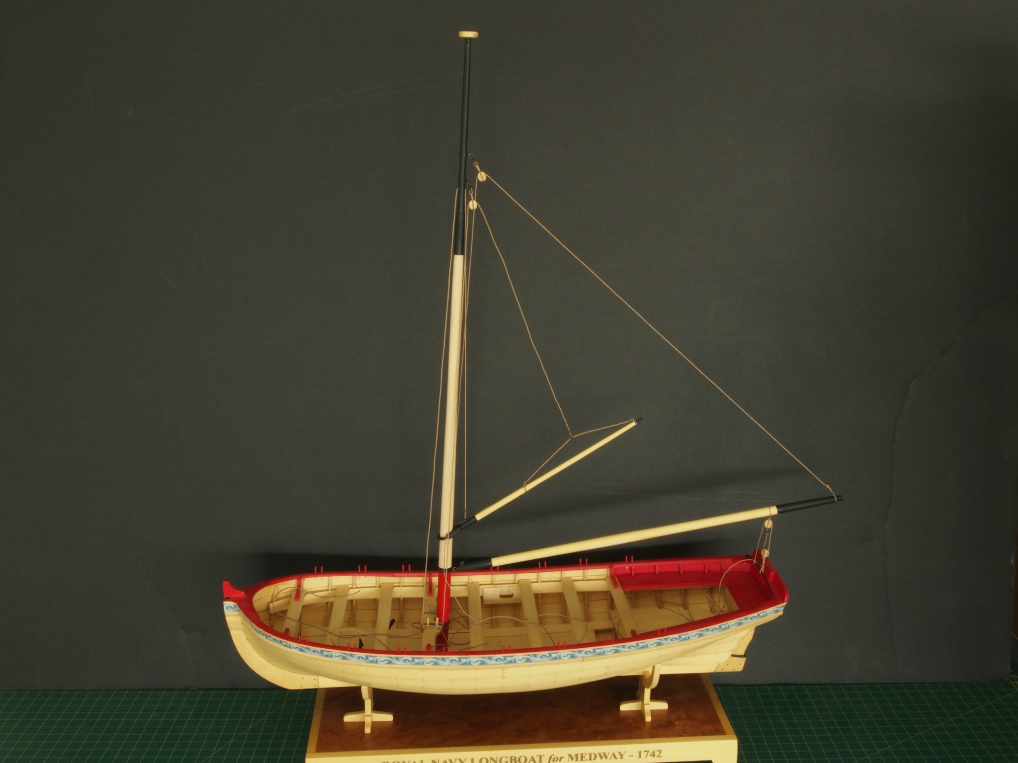
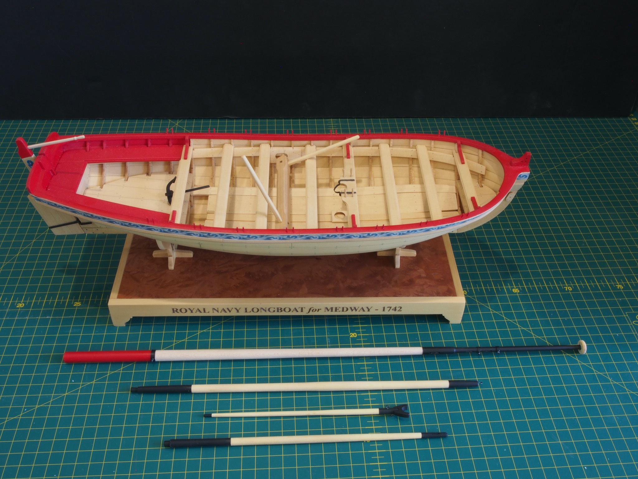
My Longboat is now complete! The finishing touches were applied today – some rope coils, the oars, grapnel and final fixing to the base. For added security, I used a 1/16” brass rod as a locator pin between the pedestal stands and the base, secured with epoxy. So here are the final photos. You will note the date on the stand says 2019….only two years late….
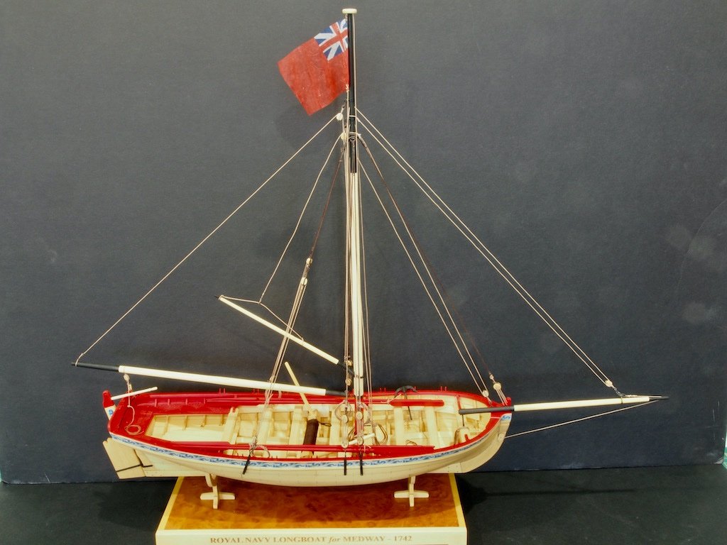
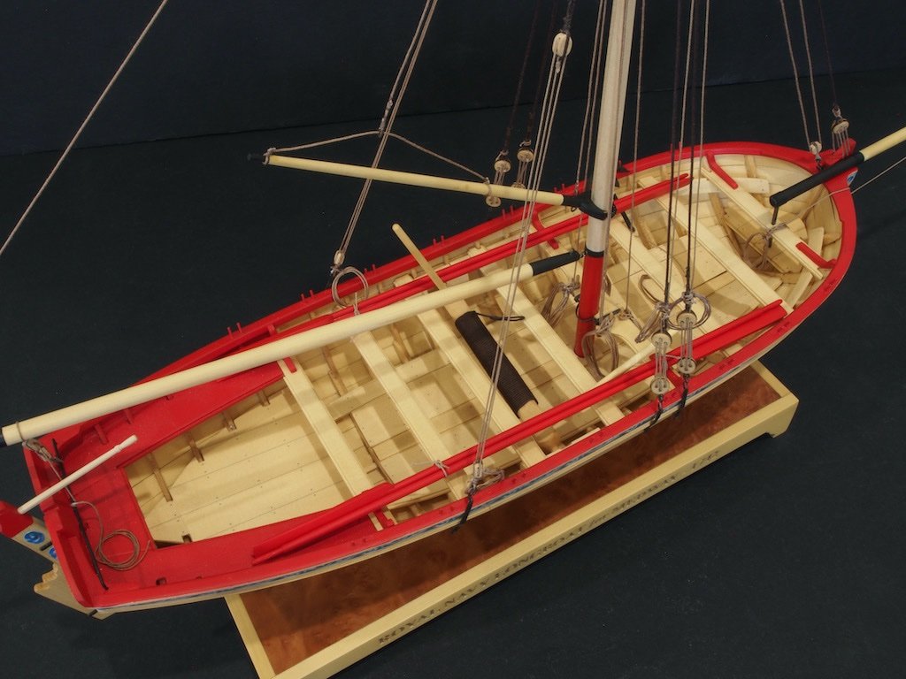
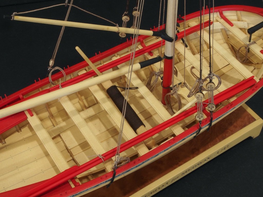
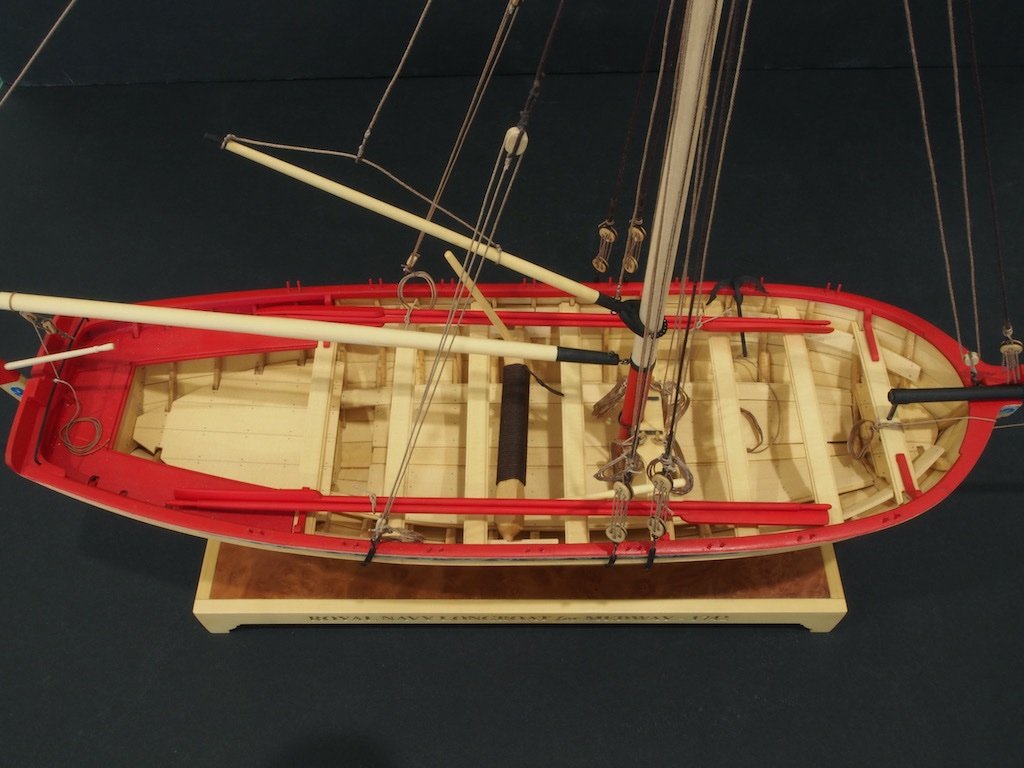
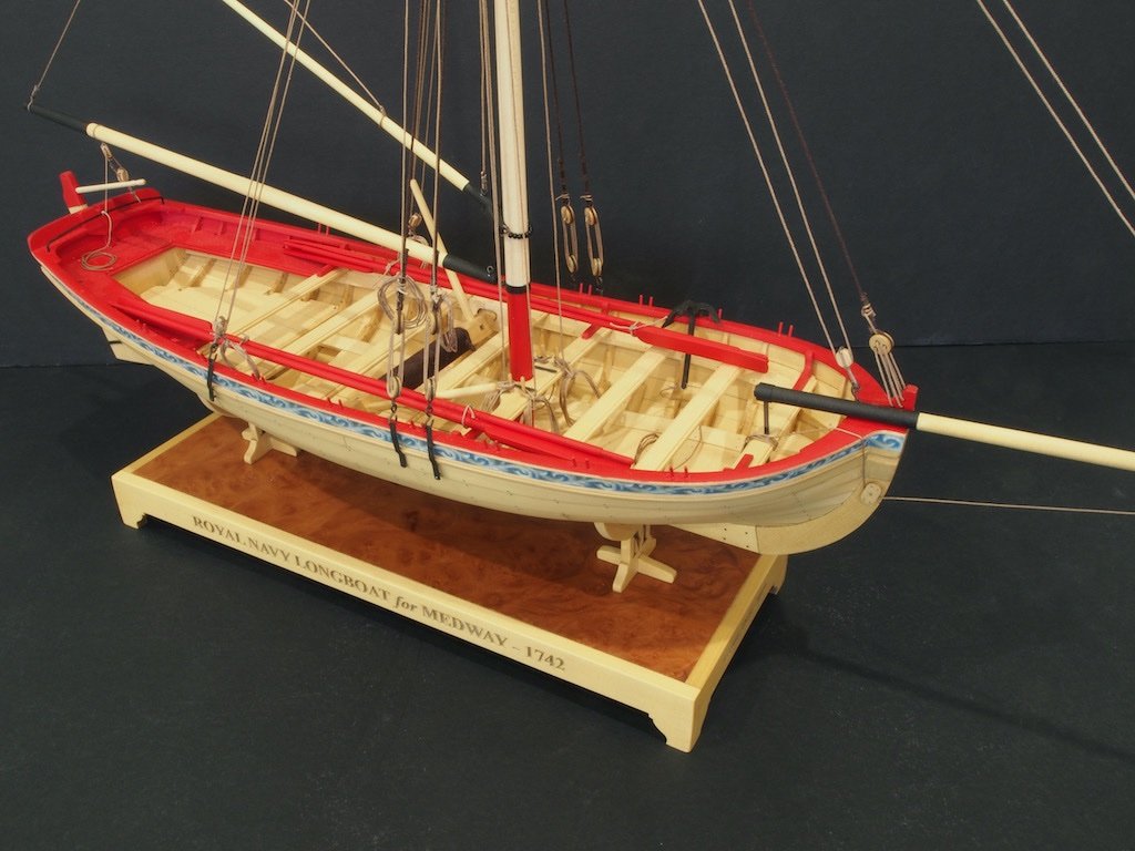
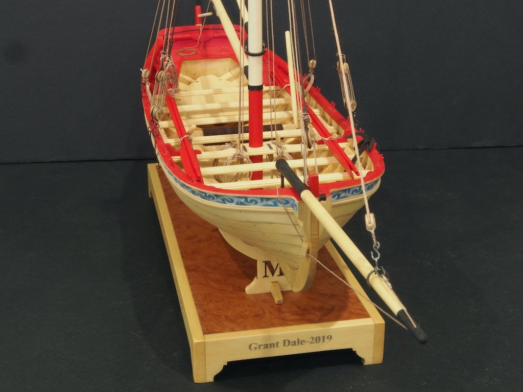
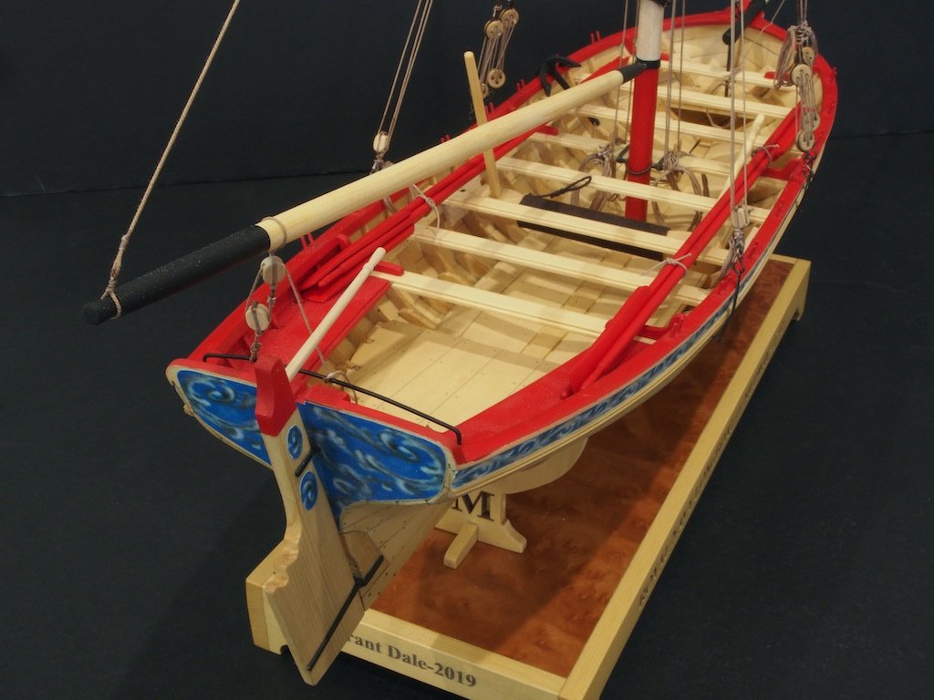
I'd like to thank you all for the kind comments and likes along the way, and a special thanks to Chuck for his ongoing support and advice throughout this build. Despite the false start and need to start over, I have enjoyed this little build immensely.
I'll see you for the next one...
-
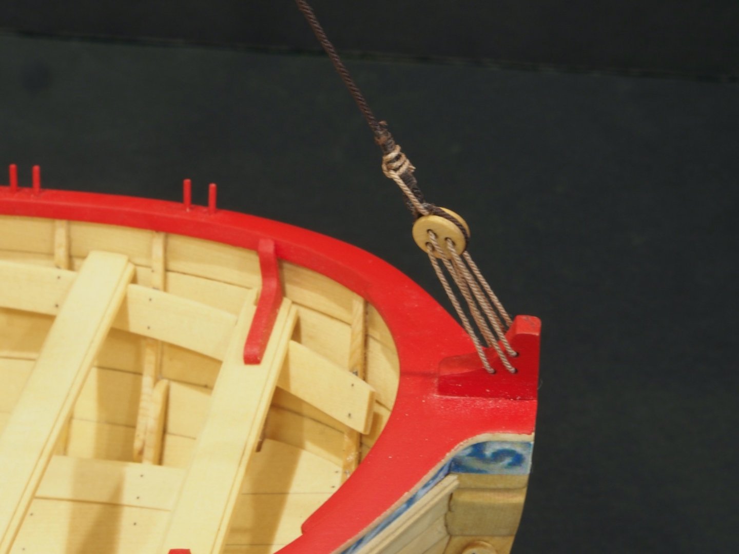
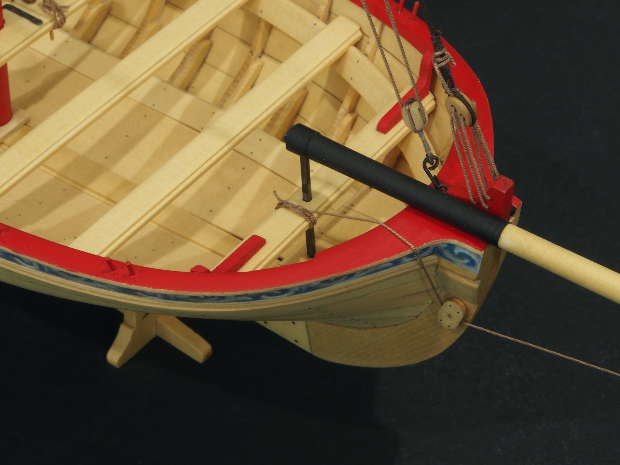
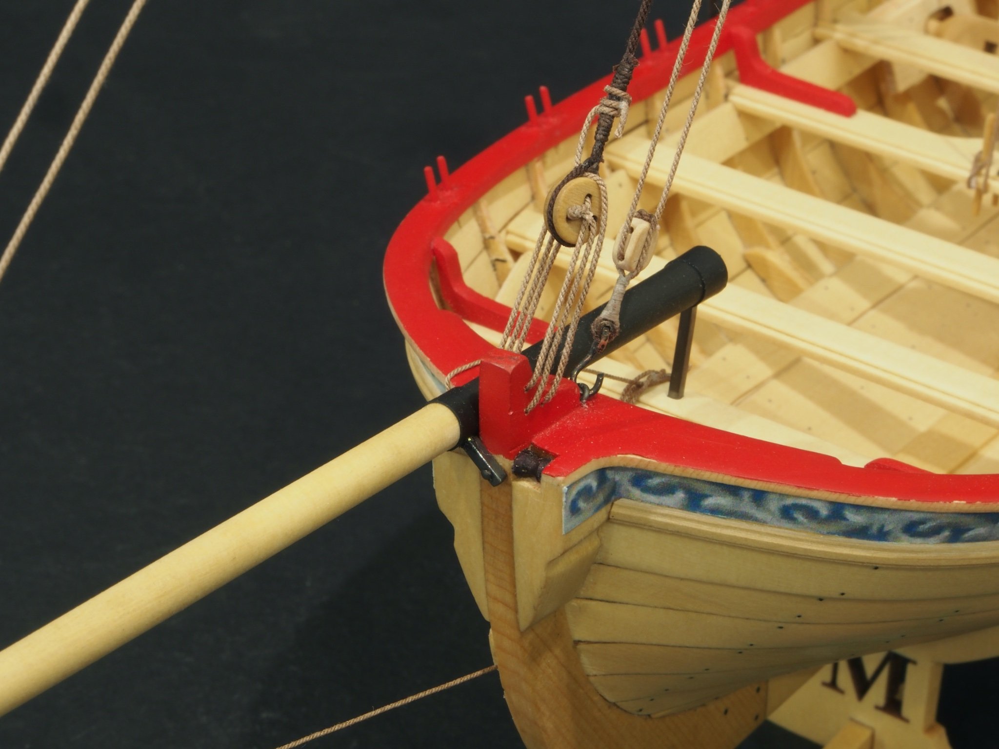
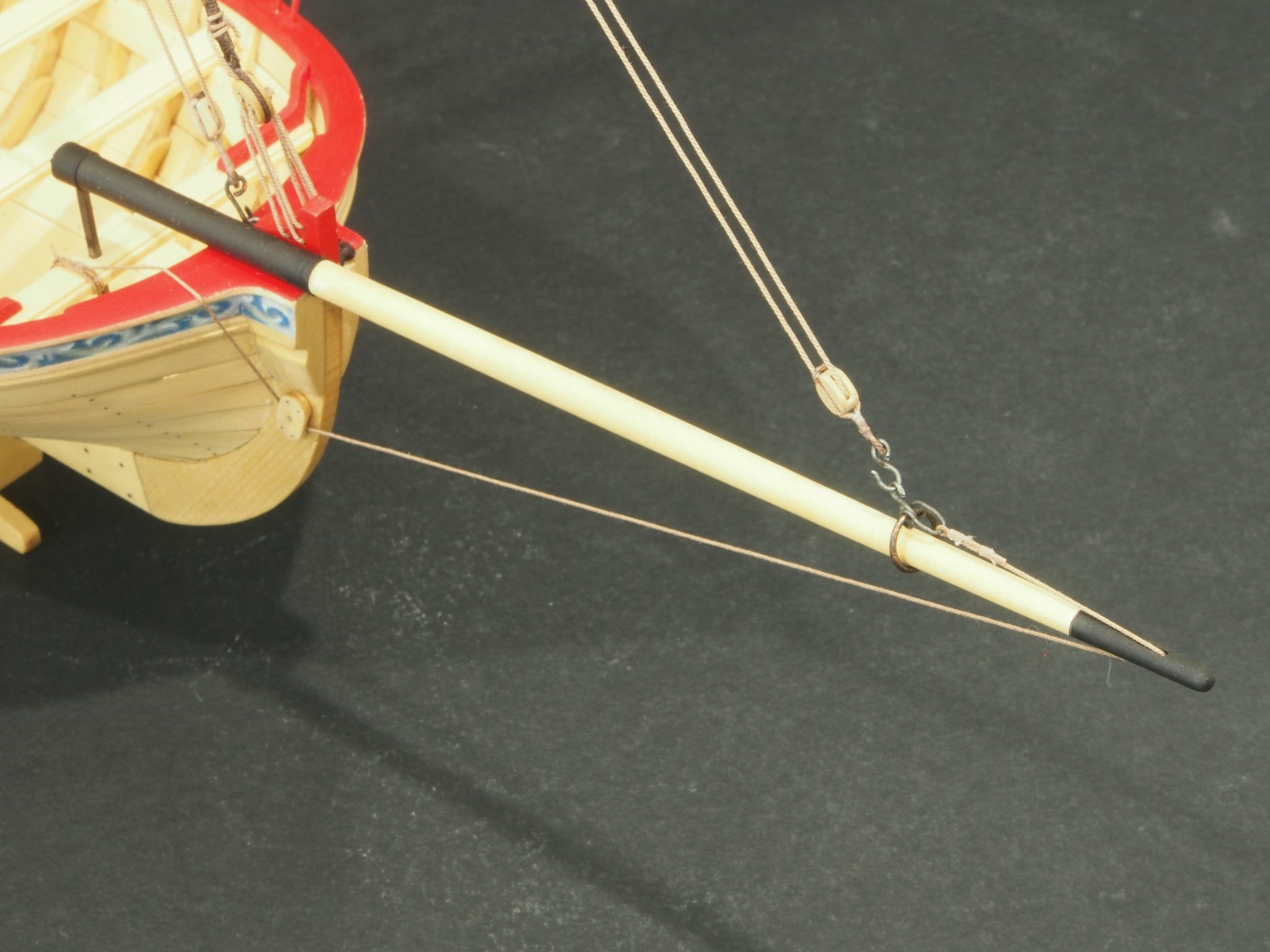
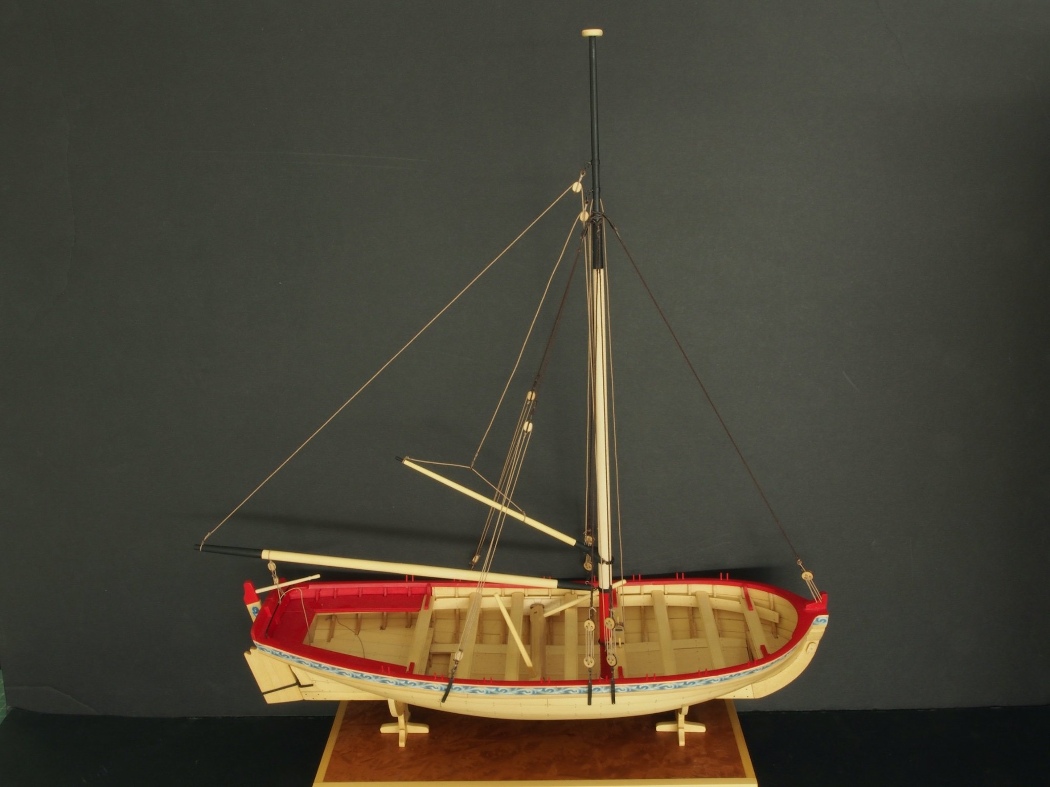
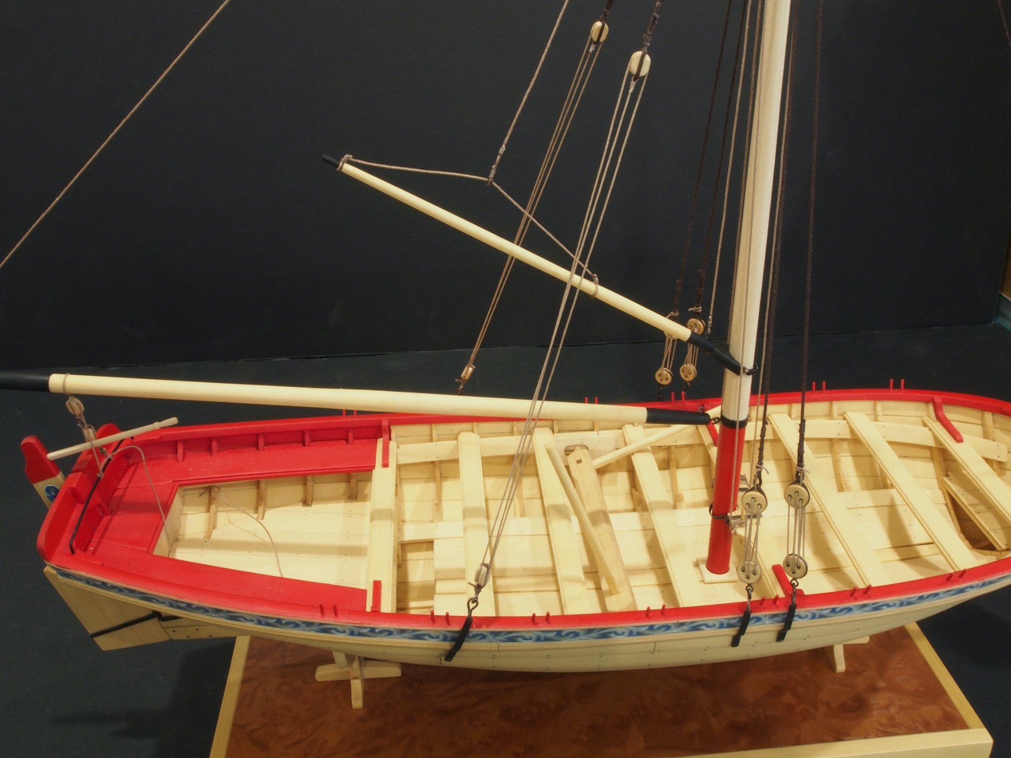
Progress has been slow but steady. Prior to installing the bowsprit, I added the foresail halyard. Then the bowsprit was added. In making the brass parts for this, I opted to pin the aft support both top and bottom by turning a 1 mm diameter pin at either end of the brass bar. This only required one re-do due to incorrect measurement of length. I again used heat shrink tubing to simulate the iron bands and am quite pleased with the way these look. Here are a few photos.


The traveller ring with hook and shackle was next, along with the jib halyard and outhaul. I just followed Chuck’s instructions here for the hook and shackle. While my shackle doesn’t look as nice as Chuck’s, I’m satisfied with it.

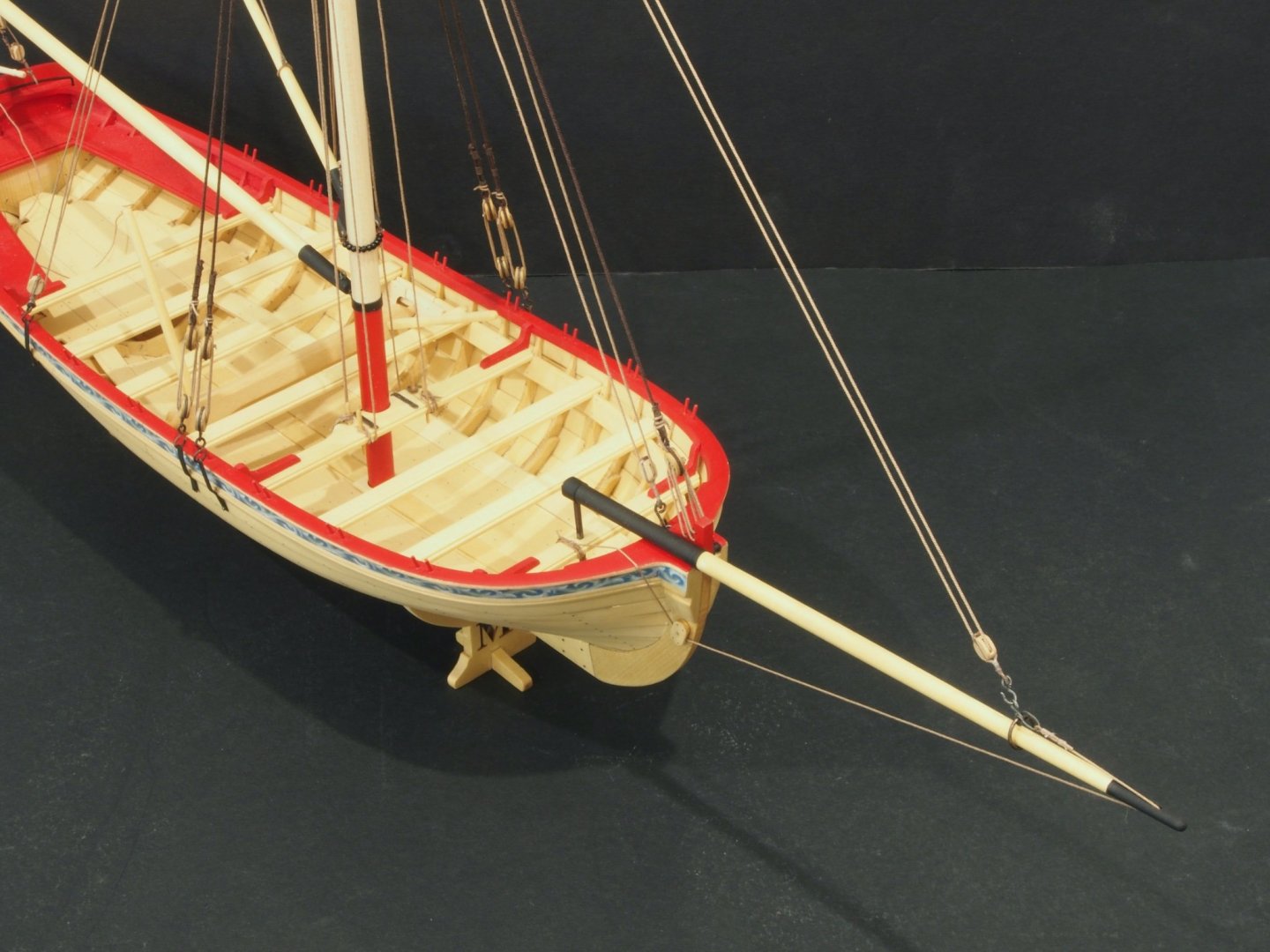
And here’s an overall shot at this point:
I have since added the Flag and some rope coils but won’t have photos of them until the final shoot.
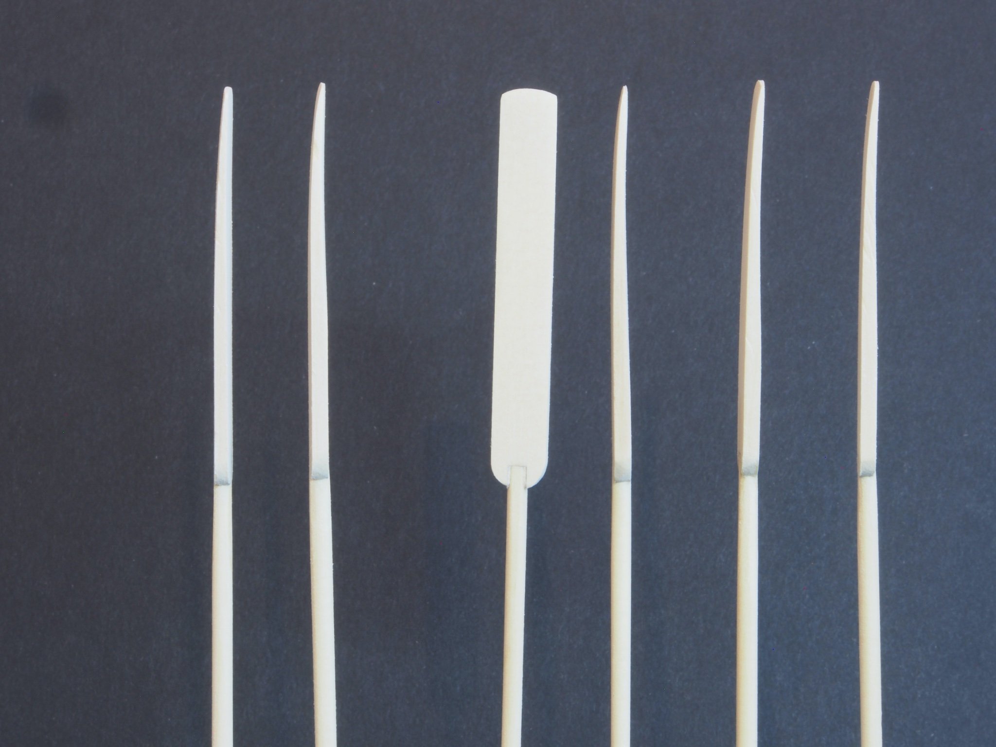
In the meantime, I’ve been working on the oars. I began by putting the square stock in my lathe and rounding it off using sandpaper. Then I turned a small section thinner for the hand grip, using very light cuts with a cutting tool and finishing off the shaping with some sanding sticks. The oar blades were then attached and shaped using some soft sanding blocks to achieve both a taper and a slight curve.
Here you can see the effect of the taper and curve:
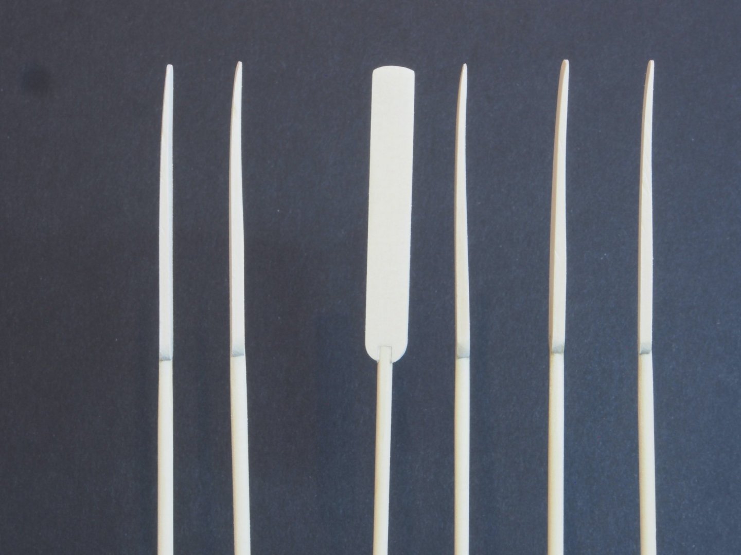
And here is a close-up of the turned handle:

The oars are currently in the paint shop receiving their livery colour. Once they are done, I have some final tidying up to do and the model will be finished. Next update will be completion shots.
-
Nicely done Andrew. She really is looking lovely.
-
Quick question for Chuck (or any others who have reached this point before me): The plans and instructions are not clear about the installation of the foresail halyard. I can see the hooked block going into the stem, and the instructions say that the loose end can be belayed to any free pin on the thwart, but where does the fixed end attach? On the plans, it looks like it might be seized to the mast above the shroud/stay gang. Is this correct?
- Canute and Ryland Craze
-
2
-
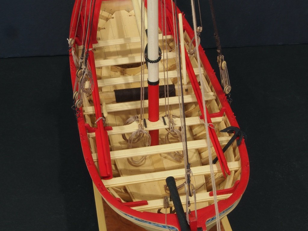
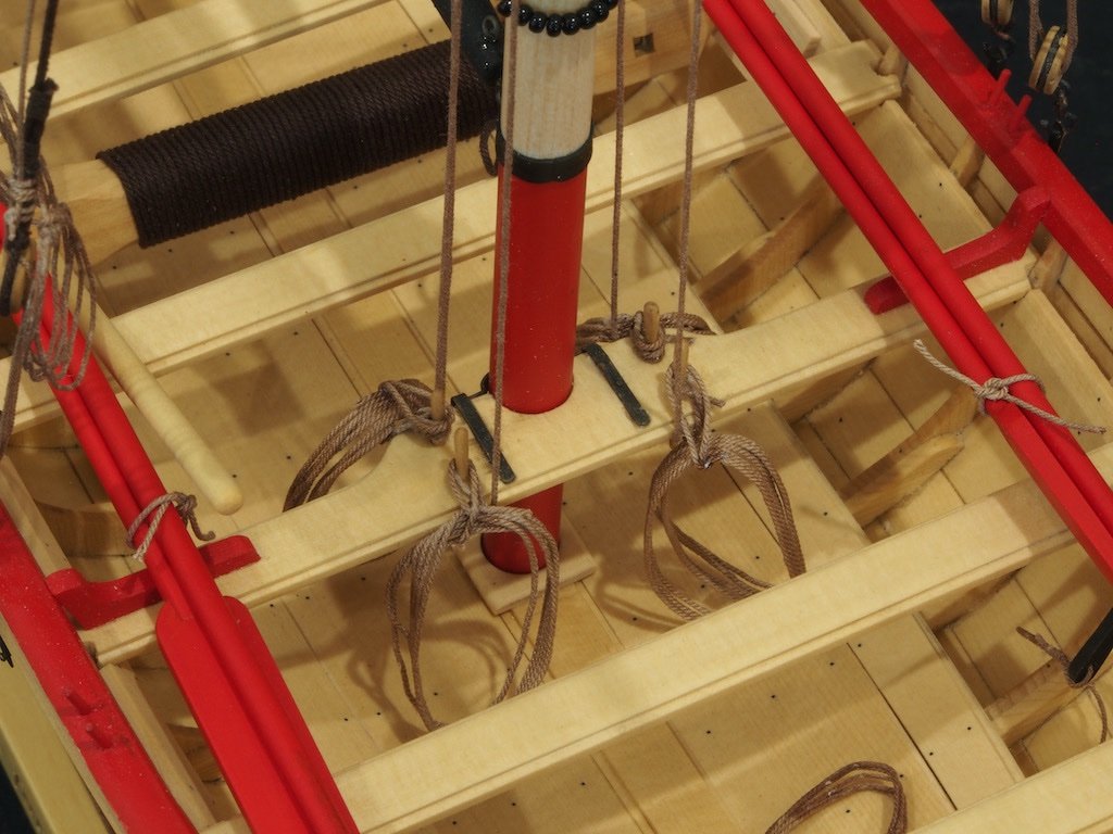
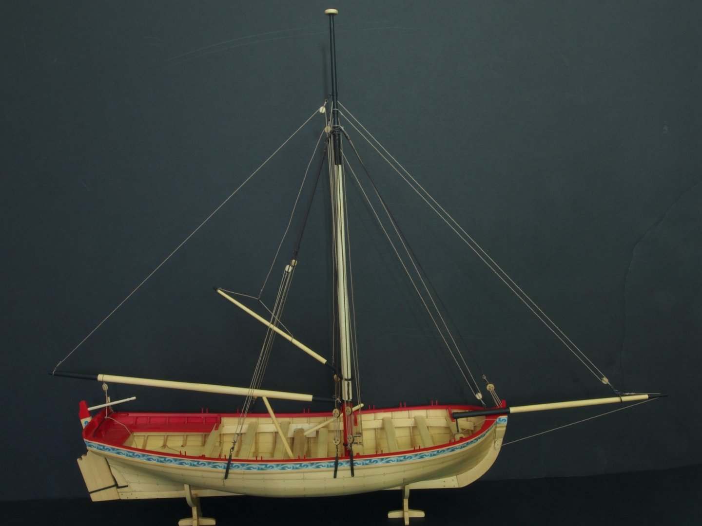
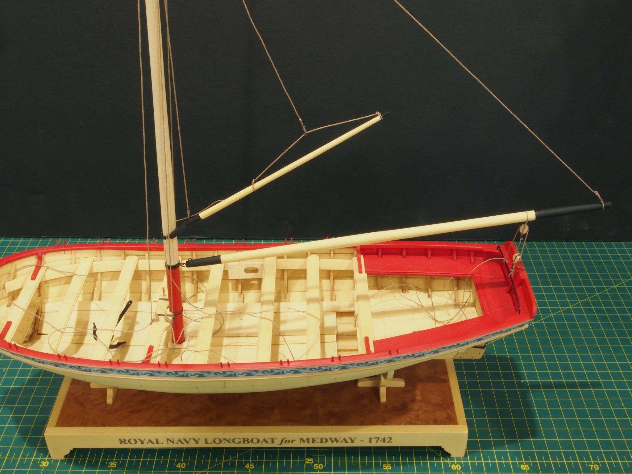
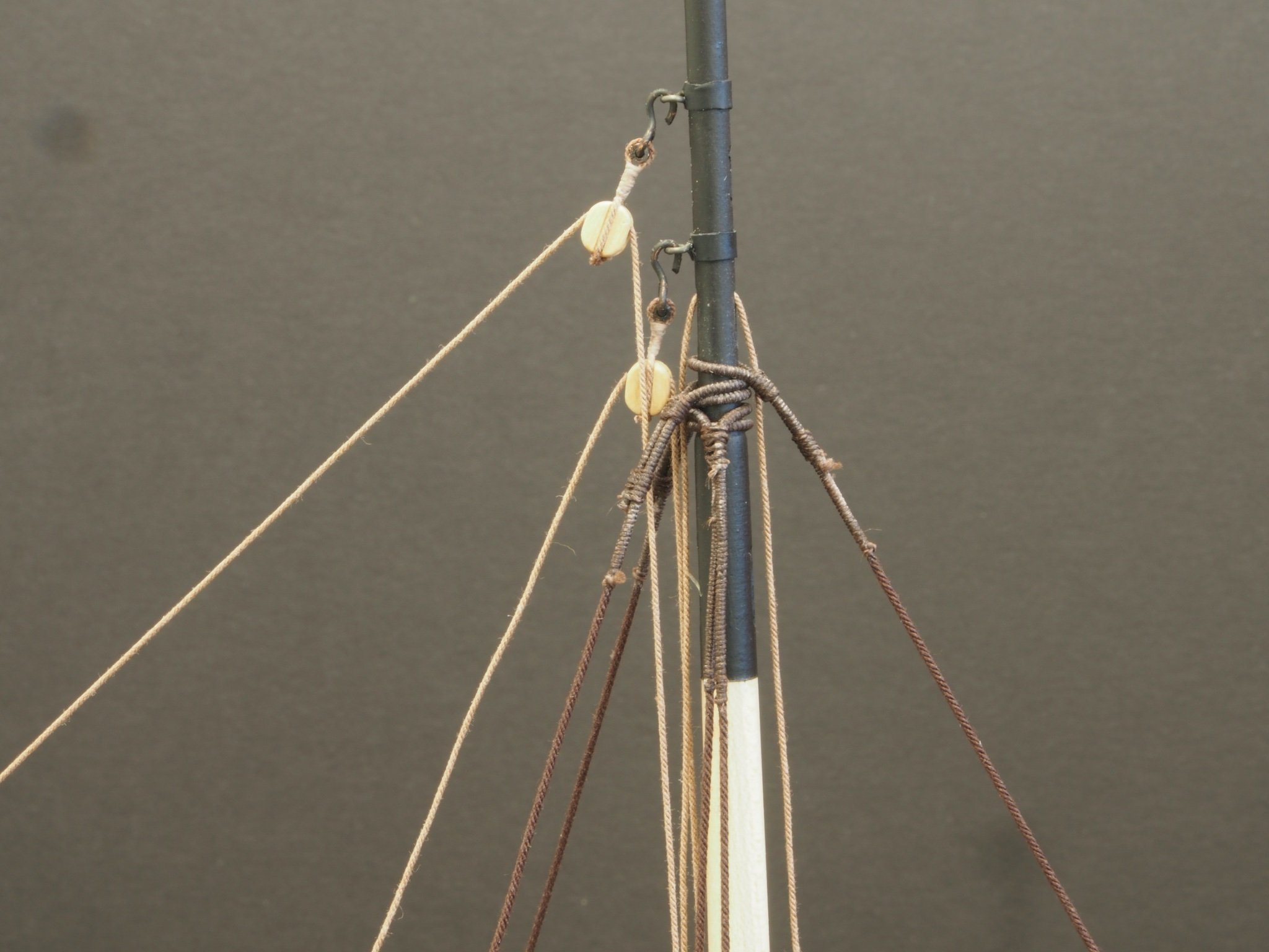
More progress! After spending considerable time preparing stropped blocks and deadeyes, and then serving sections of shrouds and stays, the rigging seemed to come together quite quickly. The Boom and Gaff were the first items added:

And a close-up showing the mess of extra lines awaiting clean-up

I got quite engrossed with what I was doing and forgot to take any progress shots until suddenly the rigging was all but finished. Here is an overall shot of where I’m at today:
This close-up shows the section of shrouds and stays that were served. I used my Domanoff serving machine to do this. The only hard part was remembering where I had put it as the last time I had used it was about 5 years ago! It was useful not only for serving the lines, but also for stropping the blocks and seizing the deadeyes.
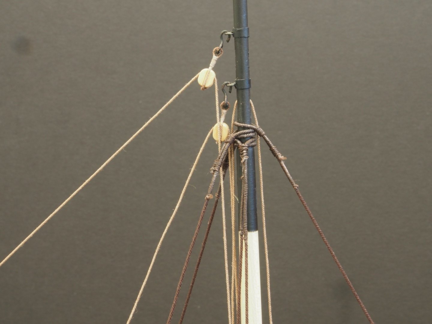
I seized the deadeyes into the ends of shrouds prior to installing the shrouds and seizing them to the mast. I decided to add a throat lashing to the deadeyes and it turned out quite well. To complete the lanyards, I threaded the ends between the throat lashing and the upper deadeye and then tied a couple of half hitches. As these were working lines, I thought it would be unrealistic to seize these to the shrouds, even if it would have looked neater!
Backstays were next. Nothing much to add here, except that Chuck says to tie these off above the lower tackle block. I thought it might be more practical to tie them off just below the lower tackle block.

The forestay was the last line added. Again, nothing much to add here. The lanyard was finished off in the same way as the shrouds.
The Bowsprit is next…
-
Great to see you back at the bench Ben. She’s looking fabulous.
- Trussben and FrankWouts
-
2
-
Thanks Per - I've just used some enamel Floquil Engine Black on the horse and it has come up nicely. I will likely do the same with the other metal parts.
Thanks Bob. Heat shrink tubing is used in electronics. Basically it is oversized rubber(?) tubing that is meant to slide onto electrical wires prior to soldering and then slide down over the solder joint. Heat is then applied (I just used a heat gun, but any heat source will do) and as the tubing heats up it shrinks down over the joint. It comes in a variety of sizes and even in tape form. I think I pinched this idea from Blue Ensign originally - very useful where any metal band is called for. I suspect it can be further enhanced by the application of some weathering powder too.
- Ryland Craze, Canute, Nirvana and 1 other
-
4
-
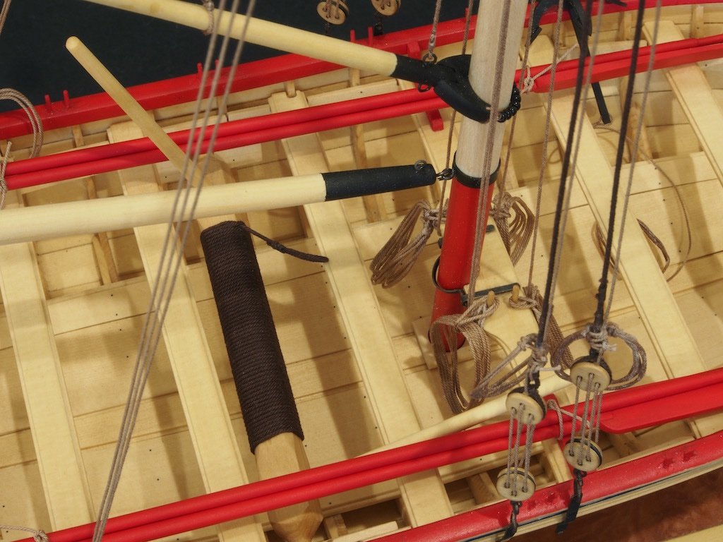
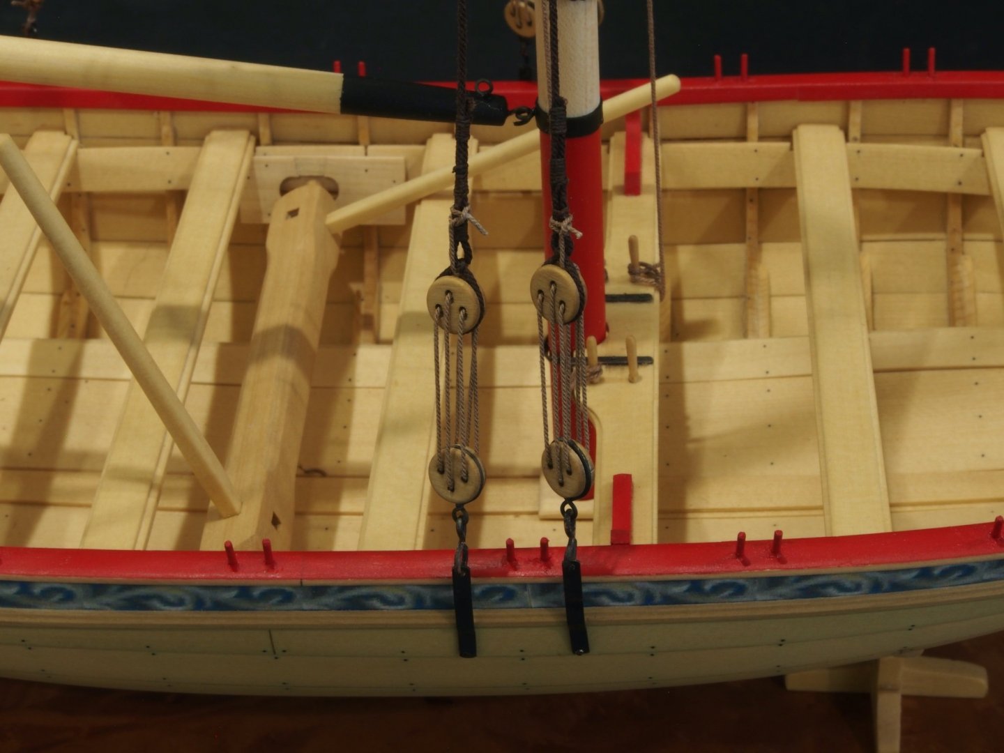
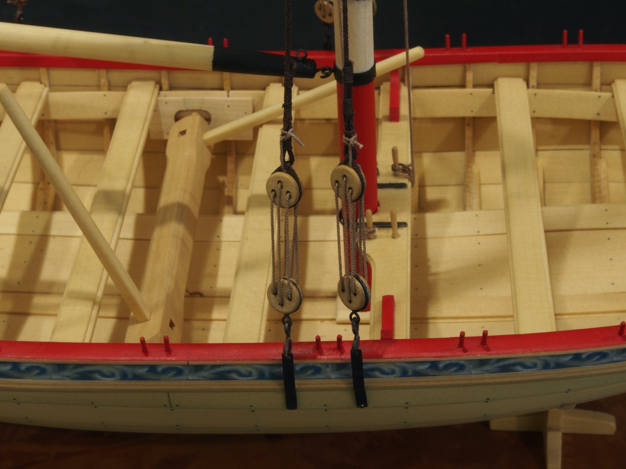
Progress has been slow but steady of late. I completed shaping and painting the Mast and Spars. Rather than using tape for the mast bands, I used some heat shrink tubing, which seems to have worked quite well. Eyebolts and hooks were made up as appropriate and inserted.

Here they are sort of in place:
I then made up a bunch of hooks and thimbles for the hooked blocks. I tried several ways of doing the thimbles, but in the end just cut some 2mm copper tubing in thin slices. I was unable to achieve the nice flare that Chuck did, but in final use I don’t think it’s noticeable. I wasn’t happy with my first attempt at making the hooks, so in the end remade them from brass rod and blackened them. The blocks were stopped with the provided 0.025” line and seized with 3/0 fly tying thread. Here are the final versions of the hooked blocks:
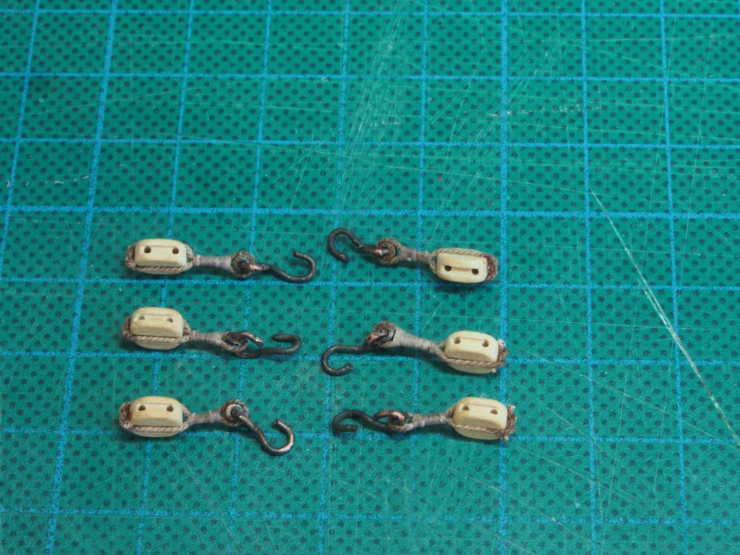
I’ve also made up the hooked deadeyes and their straps for the shrouds. I’m not altogether happy with the blackening of these parts and may end up painting them instead. I’ll do the same with the horse before starting to rig the various lines.
-
Nice save Mobbsie. That central plank I believe is called the King Plank. Still not clear why you left it off though - do you have a cunning plan?
-
Congratulations Chris on this bold move and I wish you every success. The one down side of working for yourself is that you now have a slave driver for a boss! Great to hear of your wife’s recovery too. Perhaps she can put in a good word for you and negotiate some time off every now and then!
- Canute, hollowneck, mtaylor and 2 others
-
5
-
Aha! The elusive build log has appeared at last. 😉😁
Well done mate - despite the many challenges that this kit seems to have thrown at you already, I know that this will become another “Mobbsie Special” and will look spectacular when finished.
Great to see you up and running again my friend.
-
Time for an update of sorts. Looking at my last log entry, I noted there would be slight pause while I attended to a project for a friend. That was the building of a Garden Bench / Picnic Table. It was almost immediately followed by another furniture project for home (a Hall Table), some Box-making (for charity) and then another furniture project for home, this time a Japanese-style Garden Bench to go in our newly re-modelled back yard. And suddenly, five months had passed…
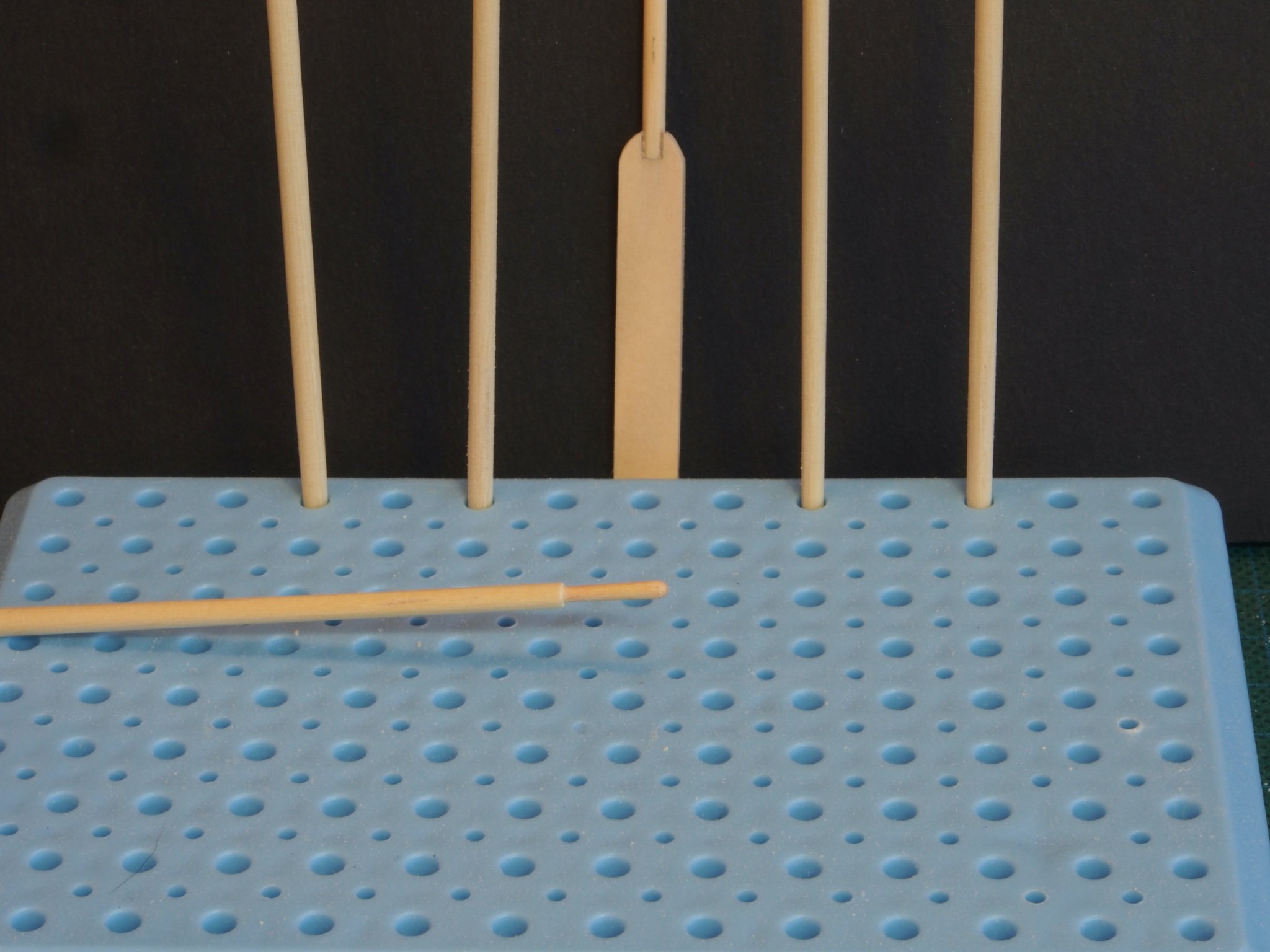
Finally, this weekend I made a start on the mast and yards. There is not much to say about this as the process has been so well documented in the build logs of others. I followed Chuck’s advice and used his templates to take the square stock to octagonal shape first. Rather than trying to use a ruler to draw the lines, I set a drawing compass to the width on the templates and just ran that along both edges on all four sides. Before doing any shaping, I drilled all of the sheave holes while the stock was still in square section. Then I set the piece in the jig shown in the middle ground of the photo below and used a block plane to bring the pieces down to size. The jig is just a piece of MDF with a 90-degree “V” groove cut into it and a stop at one end. Two different sized grooves cater for differing stock thicknesses. The planing goes quite quickly and easily.
The octagonal shapes were then mounted in the lathe and rounded off with sandpaper, applying the various tapers by reference to the plans and checking regularly with the digital callipers. The only oops I had was when I tried to get too smart with the main mast and used a cutting tool on it. Bad idea! I managed to break the mast in two. Not having a stock of Alaskan Yellow Cedar ready to hand as a replacement, I decided to use a piece of Rock Maple cut from a 12mm thick board that I had in my timber stash. This worked well and the colour is a reasonable match.
After a relaxing afternoon at the lathe, I had a complete set of mast/spars ready for the next step.


HMS Beagle by mobbsie - OcCre - Scale 1/60
in - Kit build logs for subjects built from 1801 - 1850
Posted
Looking very sharp Mobbsie!