MORE HANDBOOKS ARE ON THEIR WAY! We will let you know when they get here.
×


gjdale
-
Posts
4,880 -
Joined
-
Last visited
Content Type
Profiles
Forums
Gallery
Events
Everything posted by gjdale
-
 Looks like you're off to a great start Lou! That's an interesting set-up for making the chocks - I would never have thought of that. If I hadn't already made all my chocks, I'd definitely give that method a go. I would certainly remove the paper before gluing up. If you have difficulty removing the paper, then isopropyl alcohol will help, or for your next frames, you might like to try the technique I'm using, by first covering the timber with low tack Painters Tape and sticking your pattern on top of that. It works a treat! Can't really offer an opinion on the graphite tinted glue, but it sounds reasonable. I'll be interested to see your results.
- 18 replies
-
- 2
-

-
- granado
- bomb ketch
- (and 1 more)
-
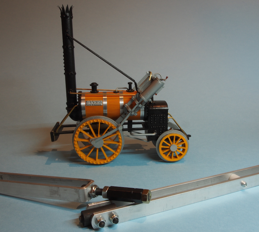
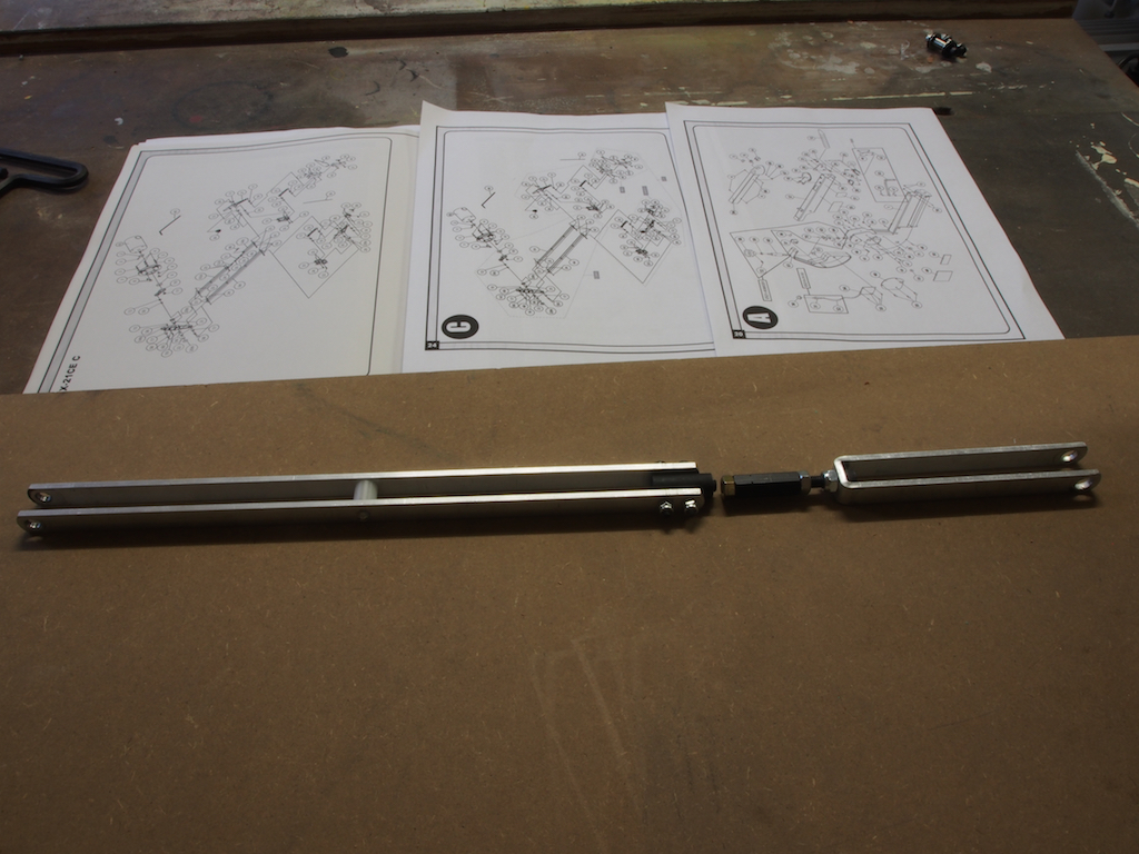
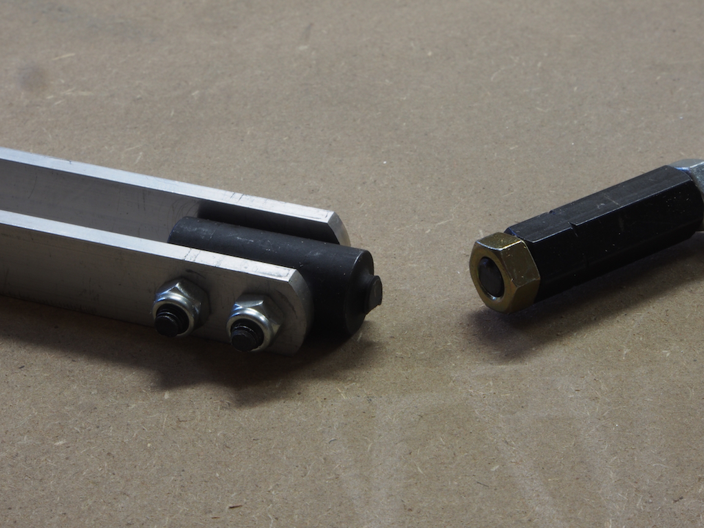
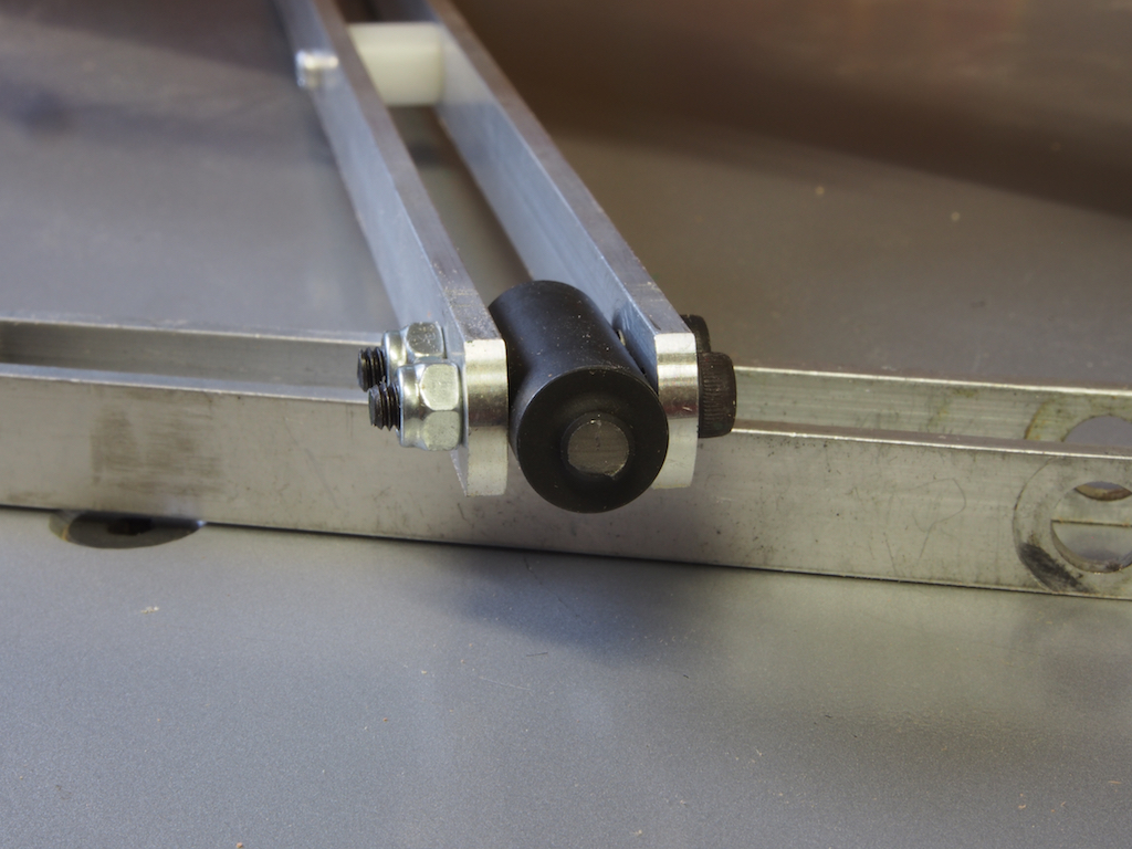
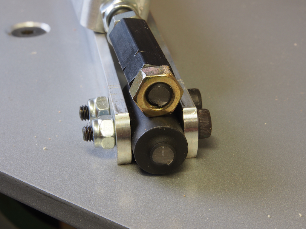
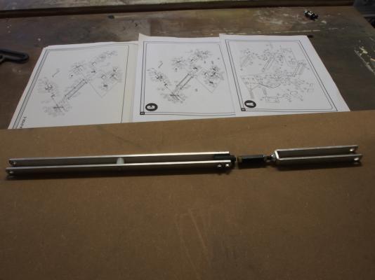
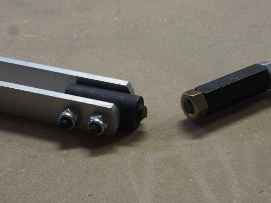
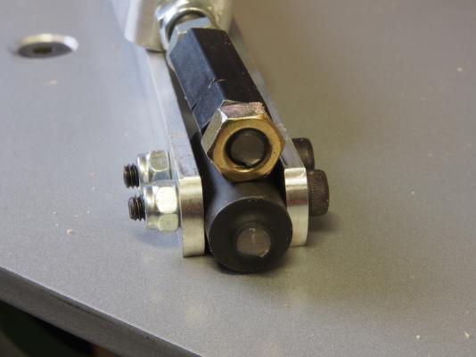
Tool Time So, while I waited for a couple of weeks to sort out with Carbatec the parts I needed, I continued with my non-ship project, which appears somehow to have leapt into this photo of my broken Scroll Saw Drive Link Assembly. It seems that General International (makers of my Excalibur Scroll-saw), have changed the design. Here’s why: This is what the upper Drive Link Assembly looks like. The schematics in the background are the only form of instructions I had for working out how to take it out! About two thirds of the distance from the left hand end is a bottle-screw arrangement. This is where the 6mm (1/4”) bolt sheered. Here’s a few close-ups: It appears that this may have been a not unusual problem and General International have changed the design - the replacement part does away with the bottle screw arrangement entirely. It's function seems to be really redundant anyway, so why retain a design weakness? The new part is simply a continuous pair of parallel arms. The hardest part was working out just how much of the saw I had to strip down to provide access to the securing points, and then work out how to actually get at them. In the end it only took about 2 1/2 hours (and a bit of colourful language) from start of disassembly to completion of the job and a fully functioning scroll saw. Happy Days! While I was at it, I followed up on some advice from Jim Byrnes regarding some issues I’d been having with the Table Saw - turns out to have been an issue with the blade (I think). I’d also had an issue with my Byrnes Disc Sander, and once again thanks to Jim’s advice I was able to rectify that problem too. Still cautious about the overheating, but otherwise it seems to be fine. All in all, a very successful day in the shop, even though no model building was achieved. Should now be all systems go for next weekend.


- 456 replies
-
- 11
-
-
- finished
- bomb ketch
- (and 2 more)
-
Great result Rusty, you must be feeling very chuffed!
-
I want to see the "27 eight by ten colour glossy photographs with the circles and arrows explaining what each one was" !
-
Hi Danny, I had a quick search but can't find Chuck's original post on his method. There is a description of my trials and mods on my Victory log on page 25, starting at post #374. Here's a link http://modelshipworld.com/index.php/topic/163-hms-victory-by-grant-dale-mamoli-scale-190/page-25 I may have "filed" Chuck's original post on the other computer. If I can find it, I'll send it to you via PM. In a nutshell, it involves the Byrnes saw, the Mill with some round-over bits, a drill press, and a jig. The process itself is quite simple and I'm sure that you would come up with your own clever mods as well.
-
The boat looks terrific Bob. And you should definitely make another to fit the stern davits, if for no other reason than I'd like to see you scratch build a POF boat! I know it would be awesome and as you have observed already, making boats is an enjoyable and interesting diversion from some of the more tedious tasks. No pressure, of course
- 1,477 replies
-
- 1
-
-
- essex
- model shipways
- (and 1 more)
-
Your detail work is just stunning Johann. It never fails to bring a smile to my face.
-
Lovely work on the tops Danny. Had you considered using Chuck's method for mass producing blocks?
-
Nicely done Sjors. The re-dos were clearly worth it.
- 1,616 replies
-
- 1
-
-
- caldercraft
- agamemnon
- (and 1 more)
-
Lovely work John.
-
Some great shots to finish off Mobbsie - she really is a monster! Clearly, you need to move into a bigger house with more display room and a larger workshop.
- 1,279 replies
-
- 2
-
-
- agamemnon
- caldercraft
- (and 1 more)
-
Very nice Dan. I'm sure your plan for display (pedestals etc) will look fabulous.
-
Gil, I used the MicroGlaze from Micromark on my stern/quarter galleries when I re-did my stern. I was very happy with the results (and it's really easy to use too!).
-
Congratulations Sjors on an excellent build. Time to celebrate with an adult beverage or three! Looking forward to seeing Aggy finished soon too!
- 1,873 replies
-
- 1
-
-
- occre
- san ildefonso
- (and 1 more)
-
Joe, I've just spent a most enjoyable hour or so reading through your log. You're doing an excellent job on her and I particularly enjoyed reading your techniques and tips on painting. Thanks for sharing so much.
- 302 replies
-
- 1
-
-
- granado
- caldercraft
- (and 1 more)
-
Great progress Bob, and I'll bet it feels good to get that "tedious" bit behind you. I reckon you should have a crack at a framed/planked boat. With your skills, I bet it would be a beauty.
-
Thanks for your answer Mark. I may have to give this a try myself. Of course, I'd first have to build the sled I've been promising myself for months!
- 172 replies
-
- 1
-
-
- druid
- sloop of war
- (and 2 more)
-
I like your use of the table saw / sled arrangement for cutting the end joints Mark. Do you feel this is more accurate than using a disc sander?
- 172 replies
-
- 1
-
-
- druid
- sloop of war
- (and 2 more)
-
I'll just add my voice to the chorus of praise Rusty - a very fine looking planking job indeed.
-
Thanks Mike. Grab a drink and some popcorn and come on over to the darkside.
-
Congratulations Jack on a truly superb build. Your Admiral should be one very happy lady! Now, celebrate completion with an adult beverage of your choice, and then (after an appropriate pause) get cracking on your Bomb Vessel Cross-section. Any update on your timber order from Jeff, or is it still first week of December anticipated delivery? I would recommend doing a few trial runs of both keel and frames with some scrap wood while you wait!
-
Mike, Nice progress. A disc sander would be a very worthwhile investment for you. It is probably the single most used tool in my shop. Very useful for shaping outside curves on frame pieces, as well as squaring off ends as you're trying to do now. You can sand any angle and/or bevel on small parts too. It's a hugely versatile tool and will save you many hours and lots of frustration. I can highly recommend the Byrnes disc sander, but others like Proxxon would no doubt be very good as well.
- 967 replies
-
- 6
-
-
- hahn
- oliver cromwell
- (and 1 more)
-
Thanks Jack - the way things are going at the moment, you'll be a month ahead of me in to time!
-
Thanks Mark, It's a special part with a left hand M6 thread. I was talking this through with Mobbsie on Skype last night and showed him the schematic of the parts/assembly. We agreed that I may in fact be able to manufacture my own replacement part if Carbatec can't come through. The most difficult part of the process will be finding a LH M6 die to cut the thread. Plenty available on line, but buying one locally could be a challenge! The other issue is access - that will be a challenge too. Hopefully, I could manage through the access hatch, but it will be tricky. Stripping the machine down to do this will be a major undertaking, to be avoided if at all possible!
- 456 replies
-
- 1
-
-
- finished
- bomb ketch
- (and 2 more)
-
Thanks guys! Alan - that's a very generous offer and one that I may well take up, depending on how things go tomorrow. Tony - you got it in one - the concrete jungle! Sjors - much as I'd like to take up your offer, unless you're springing for the airfare mate, I'm afraid it's a non-starter.
- 456 replies
-
- 3
-
-
- finished
- bomb ketch
- (and 2 more)