MORE HANDBOOKS ARE ON THEIR WAY! We will let you know when they get here.
×


gjdale
-
Posts
4,880 -
Joined
-
Last visited
Content Type
Profiles
Forums
Gallery
Events
Everything posted by gjdale
-
 Hi Aldo, Nice to see you back. I sincerely hope your health condition improves to allow you more time in the shipyard.
 -
Very nice Rusty - and thanks for the tip on the 6" wide sanding belts for the thickness sander. Might have to investigate that myself.
-
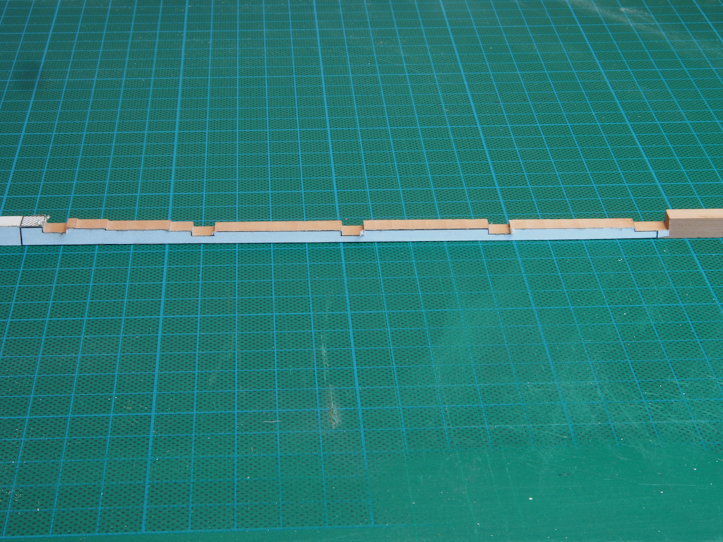
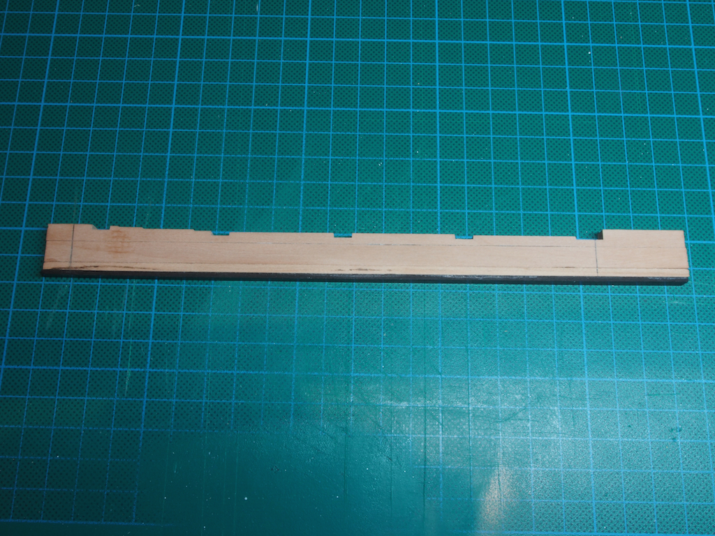
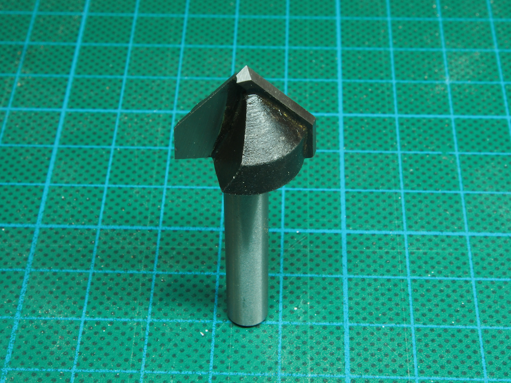
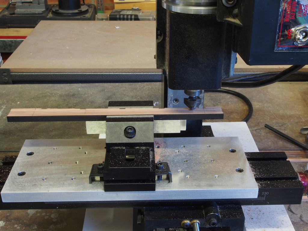
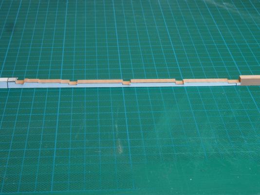
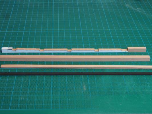
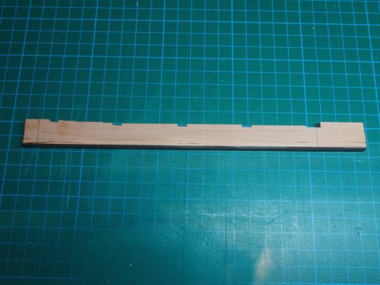
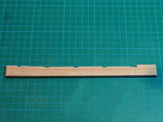
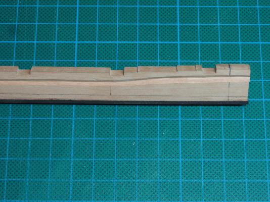
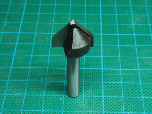
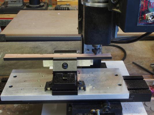
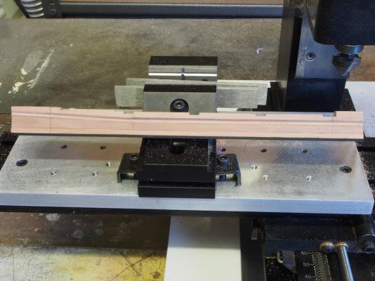
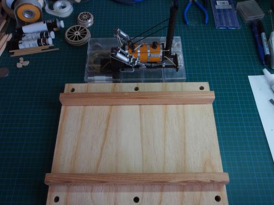
One further addition to the building jig before moving on. I added some keel retaining strips and stuck on copies of the frame position indicators for good measure. The Keel Assembly The keel assembly is comprised of four components: Keel, False Keel (Upper), False Keel (Lower) and Hog. The False Keel (Lower) is made from 1/16” thick Ebony, while the remaining pieces are all Swiss Pear. All components are 1/4” thick. The Hog needs to be cut with a series of steps and notches. Both side and top views are provided in the drawings, so I printed these onto sticky label paper to use as templates and then cut the profile using a 1/4” end mill cutter in my Sherline Mill. This was the perfect size for the width of the notches. I was quite pleased with the results. And here are the four pieces ready for assembly: After assembling the four components, I ran them through the thickness sander with a very light pass just to ensure everything was nice and even. The next job was to cut the rabbet, and this is where I ran into the first major hitch. The rabbet is straight, parallel to the keel for about 2/3 of it’s length, where it changes angle slightly and sweeps up moving aft. I cut the rabbet by hand using a very nice V-chisel. The first cut was a very, very light one and the wood peeled off beautifully. Unfortunately, this may have lulled me into a false sense of security, as I may have been a little over-zealous in the end. From this angle it doesn’t look too bad. I might have accepted this ‘as is’, until I looked closely at the second side…… You can see here that I managed to induce quite a wave into the angle part. It’s back to chisel school for me I’m afraid! I thought about this for a while and then decided to try a different approach. Enter the “Secret Weapon” This is 90º V-Groove Router bit with a 1/4” shaft. It fits nicely into a collet on the Sherline Mill. Here is the set-up I used on the mill. And here is the result: I’m much happier with this! The keel assembly was trimmed to length and is now ready for use. Next up, we start playing with frames. Oh goodie - more toys to use!
- 456 replies
-
- 15
-

-
- finished
- bomb ketch
- (and 2 more)
-
No problem Dave - answered in PM.
-
Lou, Welcome to the group. If you PM me with your email address, I'll send you a copy of the materials list spreadsheet I worked up, plus a few additional aids. You will need to purchase your own set of plans/drawings, available through the Model Ship Builder (MSB) website: http://modelshipbuilder.com/page.php?135
- 456 replies
-
- 1
-
-
- finished
- bomb ketch
- (and 2 more)
-
Nice to see you back and making some progress Chris. It certainly is a steep learning curve, but persistence will get you there in the end. Your modification at the stern looks good.
-
Looking good Sjors. Should your sprit sails hang a little more vertically?
- 1,873 replies
-
- 2
-
-
- occre
- san ildefonso
- (and 1 more)
-
Mighty fine looking progress there Mark. And what Keith said - I'll second that, with thanks.
-
Well, if Mobbbsie was concerned about the "Grant slow", it just got slower...... Tried cutting the rabbet tonight...............let's just say that more practice is required......... Looks like I get to make a whole new keel all over again. At this rate, the scrap bin is going to be well fed! I'll be back when I've got this keel and rabbet sorted. Less haste, more speed me thinks!
- 456 replies
-
- 6
-
-
- finished
- bomb ketch
- (and 2 more)
-
I'll be interested to follow along with this one Mark. Your full ship is a real beauty, so the cross section should be a piece of cake for you.
- 172 replies
-
- 1
-
-
- druid
- sloop of war
- (and 2 more)
-
Beautiful attention to detail Danny!
-
Hey Marc, Good on you for taking the plunge and ripping off what you weren't happy with. Making that decision was the hardest part - from here on it gets easier as there is no going back. I look forward to seeing your modifications.
-
I've heard very good things about the Hegner saws Kevin. I have an Excalibur saw, which I think cost around the same sort of money - it's a dream to use. Investing in quality tools is worthwhile - at least then there is only one source left to blame! And by the time you've finished your Triton cross section, you'll have saved enough money again for your Druid build and gained plenty of experience in the tool as well. Happy Days!
-
Beautifully executed Johann.
-
Thanks everyone for looking in and for the encouraging words as we step gingerly into the dark side. Welcome one and all - there's plenty of seats available and now that Mark and Sjors are both here, the bar is open and there's popcorn for everyone! I did get the keel done today, with the exception of cutting the rabbet. No pics yet, but will post some as soon as I've cut the rabbet. If anyone else wants to join in this little group build, you are more than welcome. We'll be going slow, so there's plenty of time to get caught up.
- 456 replies
-
- 5
-
-
- finished
- bomb ketch
- (and 2 more)
-
Good to see the log up and running Mobbsie. Don't go doing too much "practice" now, or you'll end up like Rusty's infamous "set-up"!
- 255 replies
-
- 2
-
-
- granado
- bomb ketch
- (and 2 more)
-
Your treenails look great David!
-
Great to see you "underway" in the shipyard again John.
- 2,250 replies
-
- 1
-
-
- model shipways
- Charles W Morgan
- (and 1 more)
-
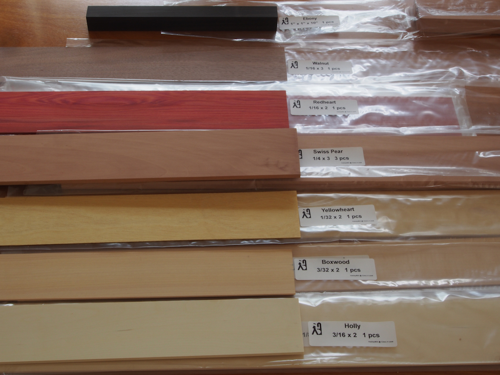
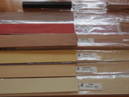
Thanks Brian, The red timber is RedHeart. It will be used for the inner bulwarks.
-
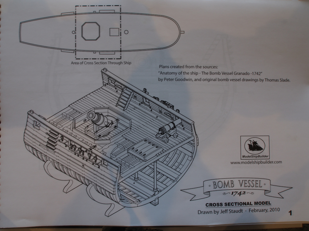
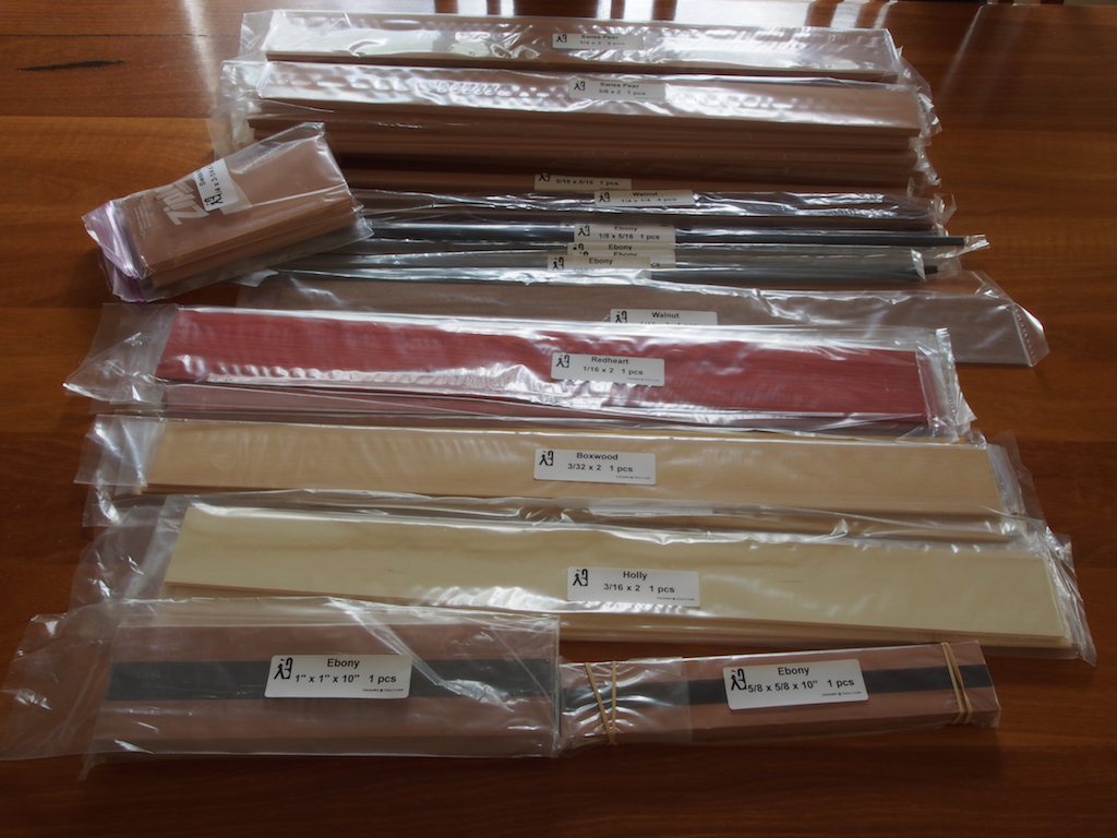
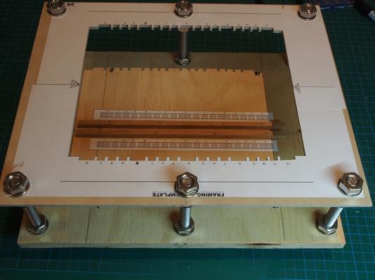
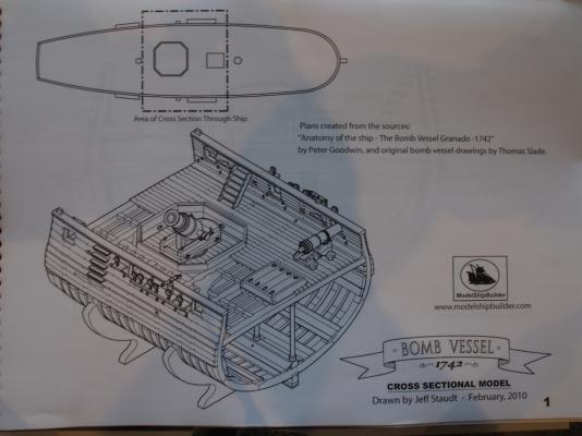
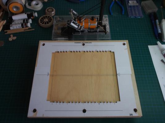
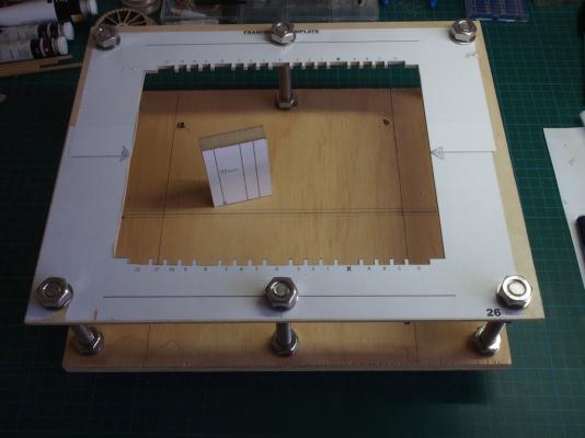
This will be my first full scratch build. I have chosen the Bomb Vessel Granado Cross Section as an introduction to scratch building as it has all of the components of a scratch build while offering something a little bit ‘unusual’ at the same time. This build is also a ‘group’ build as my very good friend Mobbsie in the UK has agreed to do this in tandem with me, and to make it a truly international build, we are also joined by Jack Panzeca from Texas. While we will all maintain individual build logs, we will progress at a common (slow) pace and will therefore be able to help each other through any tricky bits. Plans are by Jeff Staudt, based on the drawings by Peter Goodwin in the Anatomy of the Ship series, and also original drawings by Thomas Slade. The plans are available through the Model Ship Builder (MSB) forum. Although this is my first scratch build, I have to say that the plans/drawings by Jeff look to be first class. We will also be guided by the build logs of several skilled modellers who have trodden this path before us. I would like to pay tribute here to the excellent logs of Rusty, whose log of his 1:24 scale build is available here at MSW, and also of Mike41, who built the prototype model over on MSB. We will be using timber from Jeff Hayes at Hobbymill, and have chosen a selection of timbers that will allow us to “paint with wood”. My thanks to Jeff for his patience and guidance in helping me to put together the final timbering package. Of course, as you would expect, the timber from Jeff is just gorgeous. Here’s a picture of the overall wood package: And here is one showing more clearly some of the colours that we have available through these timbers: On with the show: Framing Jig We decided to start by constructing the Framing Jig - mainly because Mobbsie “cheated” by making his up earlier while testing out his new toys. It is fairly straight forward to make - the base is 12mm ply that I had lying around, while the top is 3mm “aircraft grade” birch plywood (also spare stock I had lying around). The two pieces were cut to size and then clamped together while 10mm holes were drilled to take the adjusting bolts. The pattern for the jig was then printed on sticky label paper and applied to the top, and the inside cut out on the scroll saw. After cutting on the scroll saw, the frame notches were finessed to size with a file, using a piece of 1/4” stock (framing stock) to test for a comfortable fit. The top and bottom were then temporarily joined with the bolts and the centreline transferred from the top piece to the base. The centreline was scribed into the base and then drawn over with a pencil. Additional lines were drawn parallel to this 1/8” either side to aid in locating the keel/keel supports. Lines were also drawn across the base board to denote the ends of the frames. In the following pictures, you may notice a partially completed Stephenson’s Rocket lurking in the background ……… Two battens were glued to the underside of the base board to allow for the height of the bolt heads and make the base a little more stable. A block of MDF was cut to size from the plans to make adjusting the height of the top easier, and the top was then positioned and the bolts all secured. So far, so good. Tomorrow will be the first attempt at making the keel components and cutting the rabbet.

- 456 replies
-
- 32
-
-
- finished
- bomb ketch
- (and 2 more)
-
Wow, those last few photos are excellent Ed and really show off the detail of your superb craftsmanship.