gjdale
-
Posts
4,894 -
Joined
-
Last visited
Content Type
Profiles
Forums
Gallery
Events
Everything posted by gjdale
-
 Last time I counted, it was eleventy gazillion...............but still one short when I needed it!
 -
That looks way better Sean! My only query now would be the size of the line in that aft tackle set-up (recoil line?). To my eye it looks to be a tad large for the scale - have you done a conversion from actual size to scale size to check? Otherwise, it could just be my eyes that need checking!
-
I have the Excalibur 21", purchased through Carbatec and have been delighted with it. If you pick your timing right, you can get it for about $200 or so less than their regular retail - they go on sale periodically. The only issue I had with mine was a breakage in the upper drive link assembly. It seems that since I bought mine, they changed the design and "designed out" the part that failed - which is a long way of saying, you won't have the same problem! Carbatec were excellent in their support service and helped me to identify the new parts I needed and then sent them to me very quickly. In short, it is an excellent machine and well worth the money. Best of luck with your shopping!
-
Very nice work so far Gary. Love the extra detail on the gun deck.
-
I agree with the ringbolt size comment Sean. If you can source/make some much smaller ones, I think that will help significantly. And you're right about the side tackles too.......... At least once you get the test piece right, you'll be set for the remaining 99 guns!!!!!
-
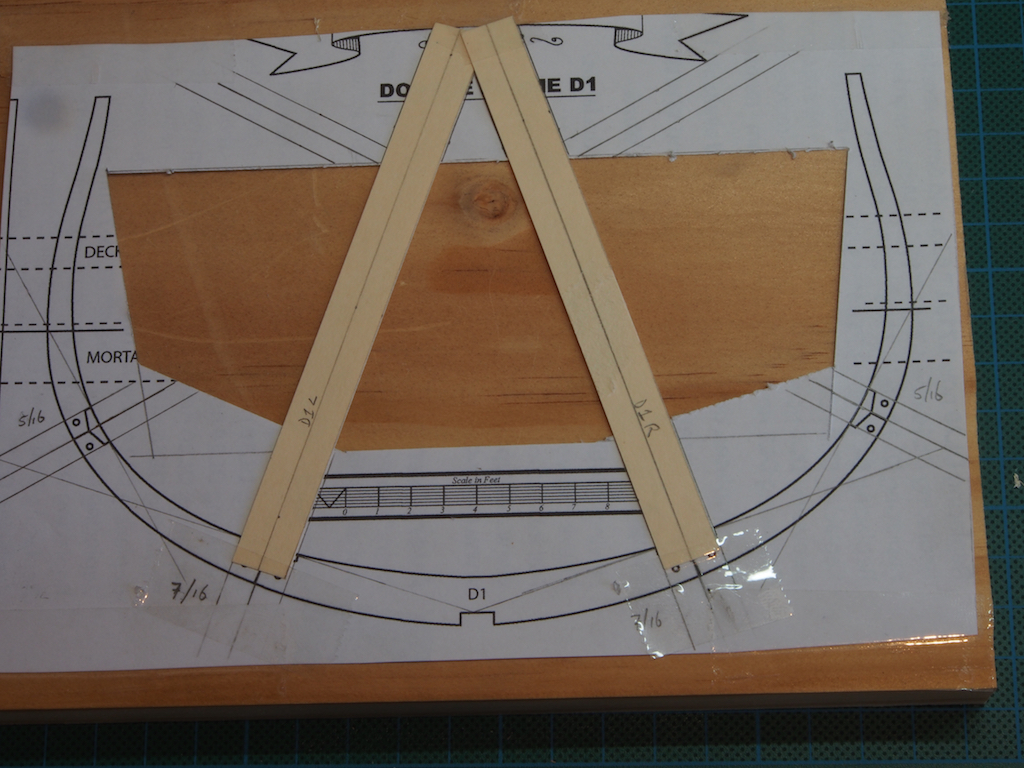
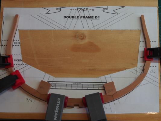
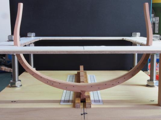
Revised Chock Making Method I wasn’t entirely happy with the chocks in my test frame and decided to try a couple of different methods. In the end, this is what I did. I first marked up some “construction lines” on the frame template, and then cut a cardboard template strip (from a manila folder) to suit the width of each of the chock sizes: Then I held the frame sections in place over the template and traced around the inside of the scarf joint to mark the chock shape onto the template. The shape was then transferred to the chock “stock” and finessed to shape on the Byrnes Disc Sander: This worked reasonably successfully, so will continue with this method for the remaining frames. Here’s a shot of the finally finished frame D1/D2, complete with blackened bolts, in position in the jig. Now to make a few more……..

- 456 replies
-
- 17
-

-
- finished
- bomb ketch
- (and 2 more)
-
It looks to me that the rear tackle (recoil rope?) isn't quiite long enough. I believe it should be able to bring the muzzle of the gun inboard (but I could be wrong here). I omitted this line on my model.
-
Yep, I was wondering about the hair-do too! Looking good Wayne - love the blanket.
-
Hi Sean, The smaller blocks are definitely an improvement and they look okay with the frapping. The only other thing I could suggest would be to have a look at Dafi's photo etch material that he supplies for a 1:100 scale Victory. I would think that the scale difference would work in your favour here. Might be worth investigating/considering.
-
Looking terrific there Bob. As Augie said, enjoy the holiday/family time, but as this is to be an "extended" visit, I'm sure "time off for good behaviour" will allow you the occasional visit to the shipyard!
- 1,477 replies
-
- 3
-
-
- essex
- model shipways
- (and 1 more)
-
Congratulations on reaching a major milestone Mark. She looks great and I can't wait to see the planking started. You must be feeling very pleased with yourself - and rightly so too, especially after the brave decision to start over when Ver 1.0 wasn't going to plan.
-
Looking good Sean. Have you considered sourcing your blocks from Chuck's Syren company? They look to be first class - way better than any other commercially available blocks.
-
Lovely little touches of detail to complement your fine build there Gil.
-
Very cleverly done Chuck!
-
I'm with Toni here Remco!!! And for Remco's next miniature challenge....................
-
That's looking seriously good Ben!
-
Just beautiful Toni!
-
Just had another thought Sean, Try checking with somewhere like Cornwall Model Boats. They carry lots of parts from the various manufacturers and might have some suitable canons.
-
Hi Sean, I just went and counted what's on my model and I have 30 plus 10, so it looks like Mamoli has stiffed you two guns/carriages. If you can't get replacements (which might be difficult after the fire they had), then two options might be to leave one port closed on each side (say, under the poop deck), or leave two ports closed on the "wall" side.
-
Congratulations on a stunning model Matija. Your attention to detail is superb, as is your craftsmanship.
-
Pen Duick 1898 by Mfelinger - 1:20
gjdale replied to Mfelinger's topic in - Build logs for subjects built 1851 - 1900
Just found your log Matija. Beautiful work so far - I just love your decking. I'll pull up a chair and follow along from here too. -
A very nice collection there Ray. Diana is looking superb.
- 536 replies
-
- 1
-
-
- diana
- caldercraft
- (and 1 more)
-
Nice to see you back at it Sean. Congrats on the new arrival too!
-
Thanks Dave, that's a good thought and worth consideration. I'll probably stick with the copper wire though as it gives me what appears to be a pretty satisfactory outcome.
- 456 replies
-
- 2
-
-
- finished
- bomb ketch
- (and 2 more)