gjdale
-
Posts
4,894 -
Joined
-
Last visited
Content Type
Profiles
Forums
Gallery
Events
Everything posted by gjdale
-
 Thank you Doc, Richard and Steve. More votes for the black option confirms the decision! Richard, I believe the bolts were one inch diameter in actual practice (from my study of the scantling table in AOTS). I have no idea what size the bolt heads would be. EdT (Naiad and Young America logs) often uses black monofilament fishing line for this purpose. I can't seem to find any of that over here, so the copper wire seems to be a good option.
- 456 replies
-
- 1
-

-
- finished
- bomb ketch
- (and 2 more)
-
Thanks Lou, Bob, Mobbsie, Alan, Joe, Steve and Sjors, and all of the "likes". Mobbsie - that's a trick of the light making it appear shiny. Viewed "flat" all appears well covered. Steve - the bolts are to hold the double frames together, so they aren't sheared through. Overwhelming opinion seems to be to go with black, which was my inclination to start with, so black it shall be. Ran into a bit of a problem with chocks agains this afternoon. Going back to the drawing board on this one and will try again next weekend.
- 456 replies
-
- 2
-
-
- finished
- bomb ketch
- (and 2 more)
-
Great update Wayne. Nice addition of detail.
-
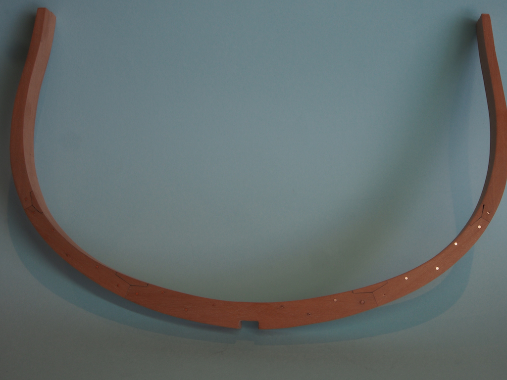
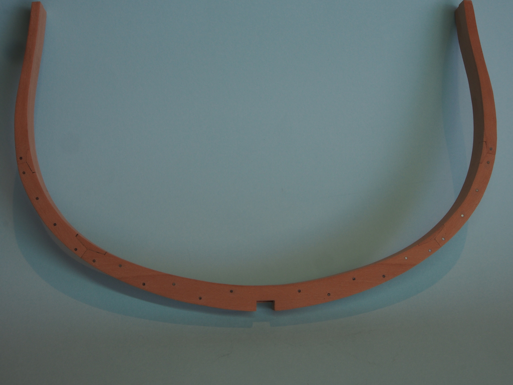
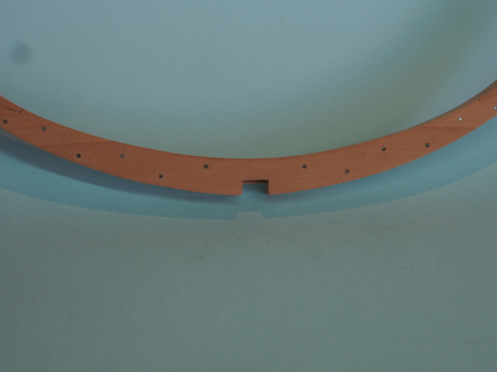
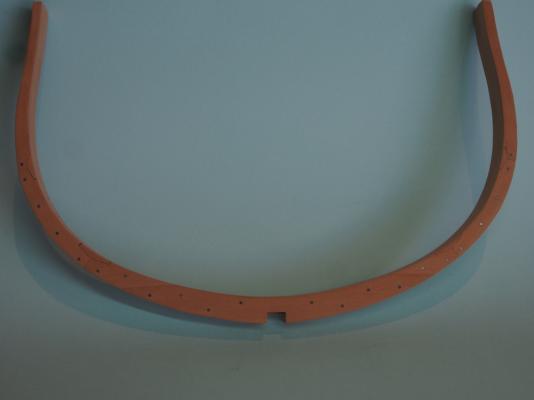
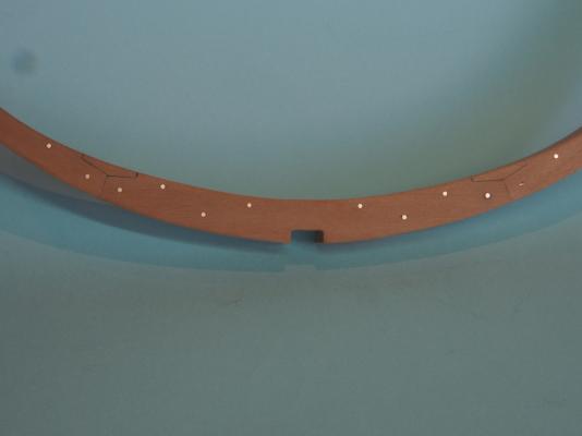
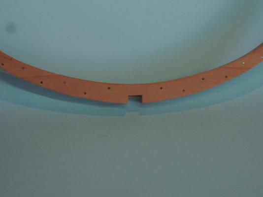
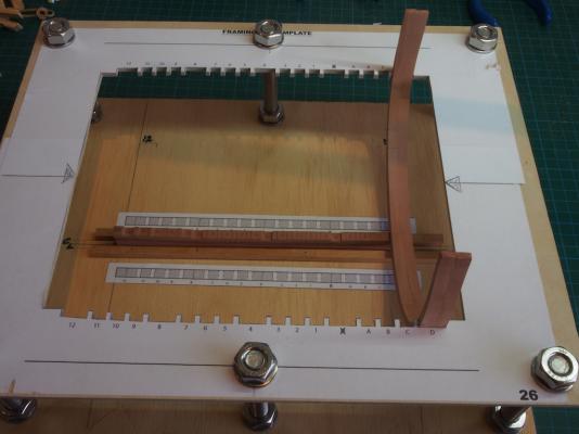
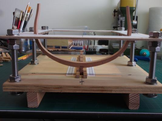
Thanks Mobbsie, Augie and Ben. Mobbsie - the overheating problem hasn't been solved as such, but I'm keeping an eye on it and if necessary will do my sanding in shorter bursts to avoid the problem. I figure that the worst case is that I will need to get the motor rewound at some point. Resumption of Play Testing of Frame Bolts Jeff’s drawings indicate large bolts/treenails either side of the chocks on the double frames. The drawings in AOTS show a significant number of additional bolts on these frames. Having seen these additional bolts added on Spanien’s build log on MSB, I decided that I would also add these. As far as I can tell from the scantling list in AOTS, these bolts would be one inch in diameter. At scale that translates to 0.53mm. Compromising between accuracy and aesthetics, I have chosen to use copper wire of 0.9mm diameter. I stretched the wire to breaking point to work harden it as well as to straighten it, giving it a final diameter of 0.8mm. I’ll call that the diameter of the bolt head, not the shaft! These were inserted into pre-drilled holes in the frames and secured with epoxy. Once the glue had set, the frames were sanded to remove excess glue and set the bolt heads flush. My dilemma now is whether to leave these as bright copper, or to blacken them (which I think would be a more accurate representation of iron). I tested this with my Test Frame D1/D2, leaving one side “natural” and the other blackened. The good thing about using copper in lieu of brass is that copper can be blackened with Liver of Sulphur (LoS), which can be painted on in situ and the excess cleaned off with water, without staining the surrounding timber. Here’s a few pics of the test pieces. Here is an overall shot of the natural copper bolts: And for comparison, an overall shot of the blackened bolts: A close-up of the natural copper: And a close-up of the blackened bolts: I’m leaning towards the blackened bolts, but am not yet decided. Opinions welcome! Here’s a couple of shots of the test frame in the jig: All looks good to proceed, so it's back to making frames and fitting chocks - properly this time!

- 456 replies
-
- 19
-
-
- finished
- bomb ketch
- (and 2 more)
-
Looking really good Augie. I like John's solution. Good luck with the negotiations - I find that bribery works quite well, especially jewelry (but save that until you're almost done, for maximum impact).
- 2,191 replies
-
- 2
-
-
- confederacy
- Model Shipways
- (and 1 more)
-
ancre LE BONHOMME RICHARD by Jeronimo - FINISHED
gjdale replied to Jeronimo's topic in - Build logs for subjects built 1751 - 1800
That is truly amazing Karl - just stunning!- 662 replies
-
- 1
-
-
- bonhomme richard
- frigate
- (and 1 more)
-
Nice work on the reef points JesseLee. By the time you're finished them you'll be an expert in placing that second knot!
- 607 replies
-
- 1
-
-
- scottish maid
- artesania latina
- (and 1 more)
-
Very nice Sjors! That bow certainly looks "ship shape".
-
Great to see an update Tony! The new jig certainly looks the business, and your frames are looking great too. I'll be doing some tests with copper bolts this weekend, so we'll compare notes after that.
- 255 replies
-
- 2
-
-
- granado
- bomb ketch
- (and 2 more)
-
soldering torch vs iron
gjdale replied to rtropp's topic in Metal Work, Soldering and Metal Fittings
Just found this alternative for the honeycombed ceramic board: http://www.gemcuts.com.au/honeycomb-ceramic-soldering-board-197mm-x-140mm-sbhcl It's AUD $38 but the size is a bit bigger. Add another $9 for postage. I just pulled the trigger! -
soldering torch vs iron
gjdale replied to rtropp's topic in Metal Work, Soldering and Metal Fittings
Pat, I'd be very interested to hear more of your investigation (and trials, I hope) with resistance soldering. Thanks also for the tip on the cheaper ceramic board - I too was stunned at the postage cost on the fohrmann one! -
Hi Lou, That's a very nice looking frame! I agree with Greg in that I think the chock would be oriented for maximum strength (ie grain parallel to the futtocks). The coloured glue does make a nice contrast, if that is the look you are after. While it does look nice, I think I'm going to stick with straight glue for mine. Interesting that you should comment on the lack of "like" notifications - I seem to be missing them as well. Keep up the good work - I hope to back at mine this weekend.
- 18 replies
-
- 1
-
-
- granado
- bomb ketch
- (and 1 more)
-
Looks like you're off to a great start Lou! That's an interesting set-up for making the chocks - I would never have thought of that. If I hadn't already made all my chocks, I'd definitely give that method a go. I would certainly remove the paper before gluing up. If you have difficulty removing the paper, then isopropyl alcohol will help, or for your next frames, you might like to try the technique I'm using, by first covering the timber with low tack Painters Tape and sticking your pattern on top of that. It works a treat! Can't really offer an opinion on the graphite tinted glue, but it sounds reasonable. I'll be interested to see your results.
- 18 replies
-
- 2
-
-
- granado
- bomb ketch
- (and 1 more)
-
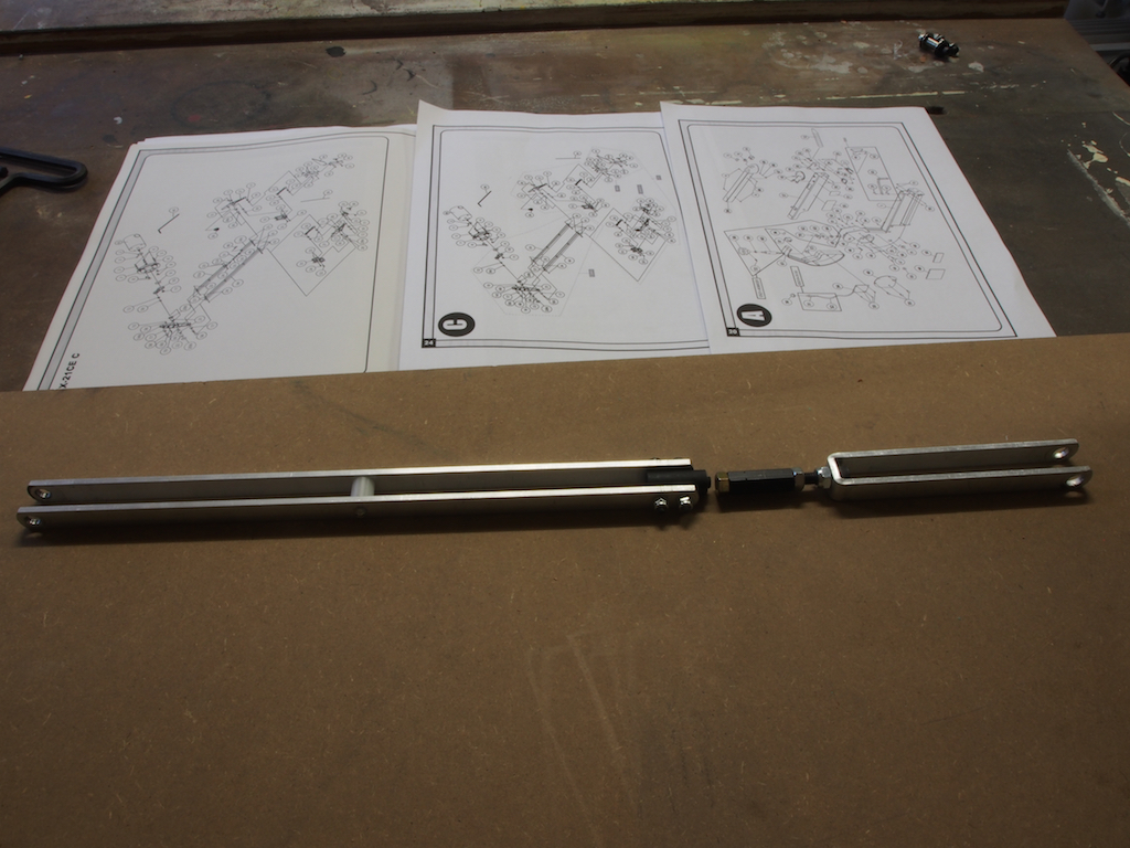
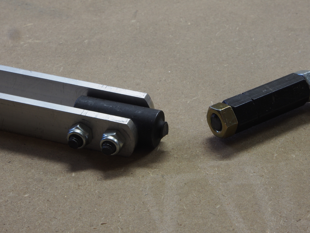
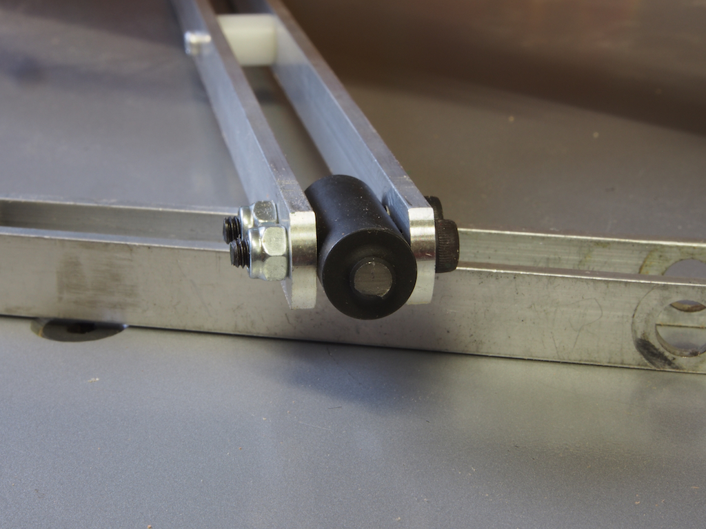
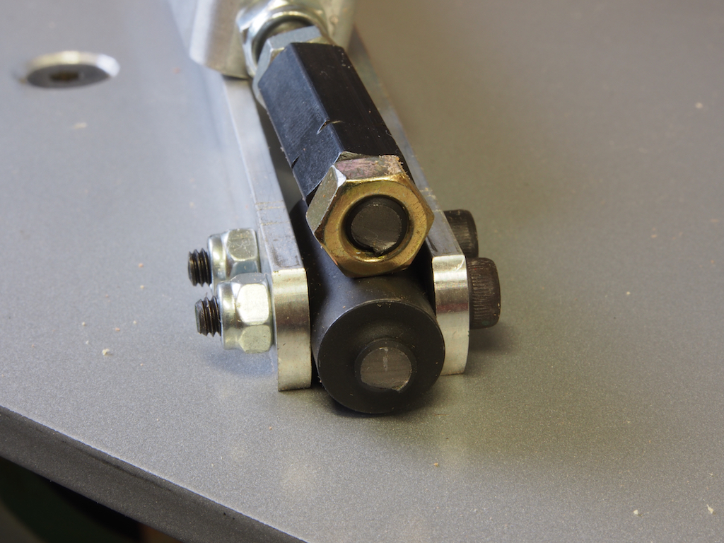
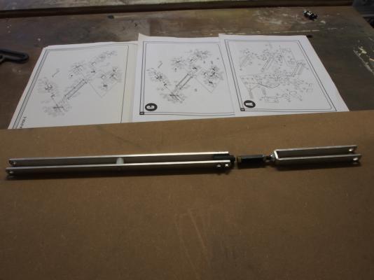
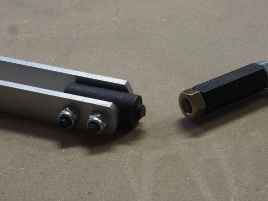
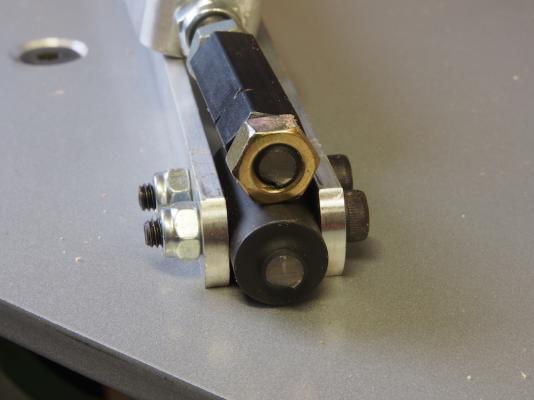
Tool Time So, while I waited for a couple of weeks to sort out with Carbatec the parts I needed, I continued with my non-ship project, which appears somehow to have leapt into this photo of my broken Scroll Saw Drive Link Assembly. It seems that General International (makers of my Excalibur Scroll-saw), have changed the design. Here’s why: This is what the upper Drive Link Assembly looks like. The schematics in the background are the only form of instructions I had for working out how to take it out! About two thirds of the distance from the left hand end is a bottle-screw arrangement. This is where the 6mm (1/4”) bolt sheered. Here’s a few close-ups: It appears that this may have been a not unusual problem and General International have changed the design - the replacement part does away with the bottle screw arrangement entirely. It's function seems to be really redundant anyway, so why retain a design weakness? The new part is simply a continuous pair of parallel arms. The hardest part was working out just how much of the saw I had to strip down to provide access to the securing points, and then work out how to actually get at them. In the end it only took about 2 1/2 hours (and a bit of colourful language) from start of disassembly to completion of the job and a fully functioning scroll saw. Happy Days! While I was at it, I followed up on some advice from Jim Byrnes regarding some issues I’d been having with the Table Saw - turns out to have been an issue with the blade (I think). I’d also had an issue with my Byrnes Disc Sander, and once again thanks to Jim’s advice I was able to rectify that problem too. Still cautious about the overheating, but otherwise it seems to be fine. All in all, a very successful day in the shop, even though no model building was achieved. Should now be all systems go for next weekend.


- 456 replies
-
- 11
-
-
- finished
- bomb ketch
- (and 2 more)
-
Great result Rusty, you must be feeling very chuffed!
-
I want to see the "27 eight by ten colour glossy photographs with the circles and arrows explaining what each one was" !
-
Hi Danny, I had a quick search but can't find Chuck's original post on his method. There is a description of my trials and mods on my Victory log on page 25, starting at post #374. Here's a link http://modelshipworld.com/index.php/topic/163-hms-victory-by-grant-dale-mamoli-scale-190/page-25 I may have "filed" Chuck's original post on the other computer. If I can find it, I'll send it to you via PM. In a nutshell, it involves the Byrnes saw, the Mill with some round-over bits, a drill press, and a jig. The process itself is quite simple and I'm sure that you would come up with your own clever mods as well.
-
The boat looks terrific Bob. And you should definitely make another to fit the stern davits, if for no other reason than I'd like to see you scratch build a POF boat! I know it would be awesome and as you have observed already, making boats is an enjoyable and interesting diversion from some of the more tedious tasks. No pressure, of course
- 1,477 replies
-
- 1
-
-
- essex
- model shipways
- (and 1 more)
-
Your detail work is just stunning Johann. It never fails to bring a smile to my face.
-
Lovely work on the tops Danny. Had you considered using Chuck's method for mass producing blocks?
-
Nicely done Sjors. The re-dos were clearly worth it.
- 1,616 replies
-
- 1
-
-
- caldercraft
- agamemnon
- (and 1 more)
-
Lovely work John.
-
Some great shots to finish off Mobbsie - she really is a monster! Clearly, you need to move into a bigger house with more display room and a larger workshop.
- 1,279 replies
-
- 2
-
-
- agamemnon
- caldercraft
- (and 1 more)
-
Very nice Dan. I'm sure your plan for display (pedestals etc) will look fabulous.