BANYAN
-
Posts
5,964 -
Joined
-
Last visited
Content Type
Profiles
Forums
Gallery
Events
Everything posted by BANYAN
-
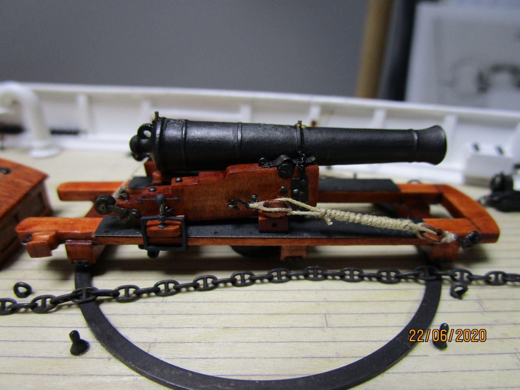
 Look good Allan and can only concur. A mate printed my 3D barrels for HMCSS Victoria using resin also, and they look good. Here is an example of a Blomefield pattern (c1847) - you can see the embossed cipher, dispart sight (forward) and Miller tangent sight abaft the breech: The gun barrel is about 1.5" long. cheers Pat (p.s. - the compressor (rear upper carriage transom) is also 3D resin printed - the bar part of the lever handle is only a few microns thick (less than 0.2 mm))
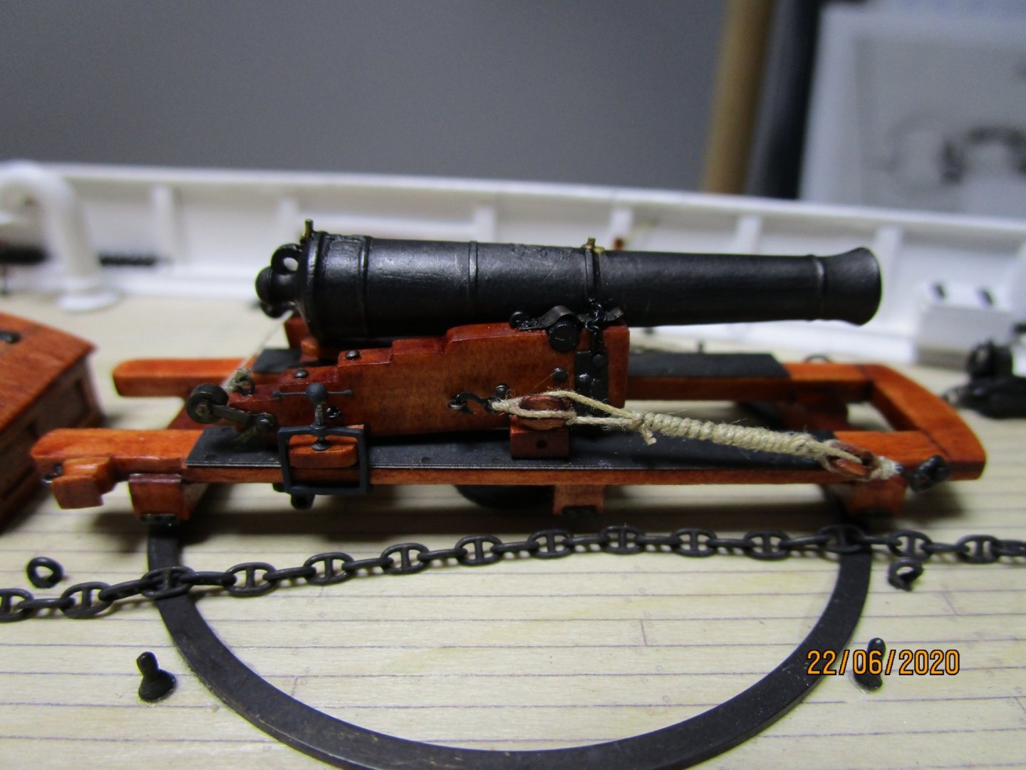
- 21 replies
-
- 11
-

-

-
Many thanks Tim, while for modern yachts/boats this may well apply. I have not yet found anything in Peake, Kipping or Fincham whom were the most prolific naval-architect qualified authors writing in the 19th century. cheers Pat
-
Hi Tim, I was not aware of any rules of thumb so I have been educated (thanks) - do you recall where you found this? I would also be interested if the rule also included some guidance on the size of the throat/centre bit in relation to the horns'. I am building a mid-19th century ship and would be grateful on any guidance you find/mentioned here. In the meantime, if I find anything I will post here. cheers Pat
-
Ah, now she really starts to show her lines. Coming on nicely Rob. cheers Pat
- 3,560 replies
-
- 2
-
-
- clipper
- hull model
- (and 2 more)
-
A great trophy for the club and a well executed half model, beautifully presented Mark. Take a bow and all due kudos. cheers Pat
-
HMCSS Victoria 1855 by BANYAN - 1:72
BANYAN replied to BANYAN's topic in - Build logs for subjects built 1851 - 1900
Thanks for the b'day wishes Kevin and Carl, much appreciated. Officially a pensioner now, will have to take a visit to 'Chelsea' Unfortunately, while the weather was reasonable, the restrictions still in place prevented more than two visitors at a time, so it was a 'staggered' family occasion spread over the weekend - most enjoyable though. Now back to the shed/workshop. cheers Pat- 1,021 replies
-
- 3
-
-
- gun dispatch vessel
- victoria
- (and 2 more)
-
Thanks for the educational approach provided in your build log Druxey. You have built yet another very nice model that is both inspirational and something of beauty. cheers Pat
- 433 replies
-
- 5
-
-
- open boat
- small boat
- (and 1 more)
-
You're doing a much better job that I could aspire to Mark. If this is what you do with your eyes crossed, well what would you achieve if .... cheers Pat
-
All the best for a quick and speedy FULL recovery Michael. I think we all need to take that break every so often, but not with such extenuating circumstances. cheers Pat
-
That hull is starting to look really good Rob; it shows the benefits of all that research you have done, such as the stem profile etc. cheers Pat
- 3,560 replies
-
- 1
-
-
- clipper
- hull model
- (and 2 more)
-
YOUNG AMERICA 1853 by Bitao - FINISHED - 1:72
BANYAN replied to Bitao's topic in - Build logs for subjects built 1851 - 1900
Congratulations on this build Bitao, it is a fine example of well executed joinery and quality craftsmanship. regards Pat- 257 replies
-
- 4
-
-
-
- young america
- Finished
- (and 1 more)
-
Nice photos and good progress Brian; looks like the adult beverages provided some incentive cheers Pat
-
Good use of your local products Michael; wish I had access to wood as easily as that. The frames look like they curve and conform to the plug quite well. cheers Pat
-
Very nice work on both the oars and the faux burle Druxey. You say you got lucky but me thinks some experience coming through here Did you use a jig to replicate the blades etc? cheers Pat
- 433 replies
-
- 4
-
-
- open boat
- small boat
- (and 1 more)
-
HMCSS Victoria 1855 by BANYAN - 1:72
BANYAN replied to BANYAN's topic in - Build logs for subjects built 1851 - 1900
Thanks for the encouragement Rob, still at a slow pace but hopefully can pick that up soon. cheers Pat- 1,021 replies
-
- 3
-
-
- gun dispatch vessel
- victoria
- (and 2 more)
-
A 'splendid' job (sorry couldn't help myself) Patrick, another wonderful miniature you are creating. cheers Pat
-
Looks good Mark; a much better job than I could achieve. cheers Pat
-
HMCSS Victoria 1855 by BANYAN - 1:72
BANYAN replied to BANYAN's topic in - Build logs for subjects built 1851 - 1900
Thanks for the encouragement Keith; hopefully something to show on the rigging soon. Thanks for looking in and kind comments Jason, appreciated. cheers Pat- 1,021 replies
-
- 3
-
-
- gun dispatch vessel
- victoria
- (and 2 more)
-
Great job on the sails Steven, as Druxey points out, remarkable definition considering the weave of the material. Good luck with the woldings on the foremast; perhaps using a curved needle (sacking/suture or the like) might assist? cheers Pat
- 740 replies
-
- 4
-
-
- Tudor
- restoration
- (and 4 more)
-
HMCSS Victoria 1855 by BANYAN - 1:72
BANYAN replied to BANYAN's topic in - Build logs for subjects built 1851 - 1900
Thanks Ed, your comments are much valued and appreciated. Slowly getting there, I am surprised how long it is taking me to finalise the rigging plan cheers Pat- 1,021 replies
-
- 4
-
-
- gun dispatch vessel
- victoria
- (and 2 more)
-
Very neat work on those rabbets Michael, very crisp and clean. cheers Pat
-
HMCSS Victoria 1855 by BANYAN - 1:72
BANYAN replied to BANYAN's topic in - Build logs for subjects built 1851 - 1900
Thanks for looking in and kind comments Mark, Keith and Druxey; much appreciated. I am about to tackle the flag locker and a few remaining very minor fittings (Lead's man stanchions and belt, Fish davit etc.); I will then do a photo stack image of the full upperdeck to ensure all is in focus. cheers Pat- 1,021 replies
-
- 2
-
-
-
- gun dispatch vessel
- victoria
- (and 2 more)
-
YOUNG AMERICA 1853 by Bitao - FINISHED - 1:72
BANYAN replied to Bitao's topic in - Build logs for subjects built 1851 - 1900
There's only one phrase to repeat, and repeat, for your work - stunning work! cheers Pat- 257 replies
-
- 4
-
-
-
- young america
- Finished
- (and 1 more)
-
74-Gun Ship Gun Deck by Jeronimo - FINISHED
BANYAN replied to Jeronimo's topic in - Build logs for subjects built 1801 - 1850
Lovely work as usual Karl; looks great. cheers Pat