Snug Harbor Johnny
-
Posts
1,513 -
Joined
-
Last visited
Content Type
Profiles
Forums
Gallery
Events
Everything posted by Snug Harbor Johnny
-
 Some years ago I did see a demo of aluminum-to-aluminim 'solder' at a wood working expo ... a thin rod of aluminum alloy with a melting point a little less than common aluminum for cans or shapes found in hardware stores. It was a no-flux heating of parts to be joined until the solder rod flowed and, to my surprise, the items joined. I bought a small bundle of rods, and they sat around for years. But eventually I had to use one and it worked. I had to heat carefully, because of the danger of MELTING the metal parts. I figure it is actually closer to a 'weld' than a 'solder'.
 -
Tools described
Snug Harbor Johnny replied to bruce d's topic in Modeling tools and Workshop Equipment
"I'll do it first." meaning the first chance I get. -
A.) Looking at the images of the work done so far, you only need to modify the planking near the bow. Starting several inches out, draw a pencil line that show the top three planks tapering down to nothing as the line ends up where the top of the third plank from the bottom 'should' be (more or less). Cut carefully along this line with a couple of light cuts using an X-Acto (a flexible steel ruler can be a guide - temporarily taped in place with blue painter's tape as you go). You're only going partway down into the planks, so you can go back and pare the face of the planks with the knife held even with the surface of the planks. This will be a controlled 'whittling' , and you don't have to go down all the way to the first planking either. The lower planks can then be sanded down gradually (surface tapered, actually) until they are thin at the bow. Glue planks with the shape you want over what's left after sanding. Then once the glue is cured, the added material can be sanded until the added wood is 'fair' with what they were glued to. Then you can continue planking with tapered planks up from there. B.) If that seems involved, you can glue strongly tapered planks at the very forward end to produce a triangular 'adjustment' ... a sort of 'fill-in' so you can plank normally up from there. When the model is mounted, the area in question will be very hard to see ... in other words, few people (if any) will notice what is way 'down under'. C.) Ships of this type were likely coppered, so if you take any one of the coppering options (a lot is on the forum about that) the planking underneath can be far from exact due to being subsequently covered.
-
Rubber cement and other 'contact' cements have failed for me over the course of years, so are not recommended for applications meant to last for decades. This is why I take exception to some kits showing the use of contact cements for model building. 'Just saying.
-
I share the same stropping concerns - a reason that 1:96 may be the smallest scale I'd care to work in. Reference Popeye the Sailor's log on the 1:124 Sergal Thermopylae to see how it can be more finicky, and still many components can go 'out of scale'. Louie da Fly is working on an even smaller scale model of Henry Grace a Dieu, which has a build log. Kits at around 1:70 can be more manageable - e.g. many of the OcCre kits. As to our respective 1:96 classic models, Rob has several fine logs of ships based on the Revell Cutty hull. He has used the blocks in the kit - like in the current log of Glory of the Seas, perhaps because many of the blocks were 'internally stropped' by the time of the clippers and had an iron ring on one side. I suppose wood blocks could be stropped with beading wire depending on the configuration needed; e.g. a hook on one end, a hook plus a ring on the other end, double ringed ... I'm no rigging maven, and will have to consult the many sources available. There are posts showing ways of using mini clamps or fly-tying implements to assist in stropping with miniature rope. BTW, I bought a Rope Rocket from Chuck at Syren Ship because I'd like to try spinning my own modeling rope - a vast improvement on most of the rigging thread around. You can also buy scale rope from Syren or Ropes of Scale. Rob is placing furled sails on his Glory, which (per photos of real ships) ... more to follow
- 481 replies
-
- 1
-

-
- Cutty Sark
- Revell
- (and 2 more)
-
The wood deck looks sharp, mate ... really fine. 'Looks like you got the oak option from HisModels - I have a vintage Thermopylae model that I ordered a birch deck for when I get around to building. Hands down, adding a wood deck seems better than trying to paint plastic to look like bare wood. Now some have done well with paints, but ... real wood is real wood. Now, where wood was painted on the original - no problems painting the molded parts. Removing the triangular 'stanchions' was also a good move, as you can replace them with better realism. Wood blocks and deadeyes for full rigging should look great. Fair sailing! Johnny
- 481 replies
-
- 2
-
-
- Cutty Sark
- Revell
- (and 2 more)
-
When picking a kit, one can see if there are builds of that kit already on site. I have an interest in the Oseberg Viking ship, and read two or three builds on the recent Billings kit. I could see every step they builders took, and noted their comments on what they liked or didn't like ... and the solutions they used in each situation. Selected pictures were screen-captured and printed for reference. That gave me a good feel for how I could go about it as a future project - so I ordered the kit to be sure I'll have it when the time comes. And then I'll revisit those builds again, since I'm in the middle of a build myself. I've learned a LOT from other builds (not all complete, but many are far along the way) on my present build, and have made alterations based on the gain of knowledge. Let me tell you, doing something for yourself is a great teacher - and many things can be corrected or otherwise 'done over' as you go. Ultimately, a builder does a project for self-satisfaction regardless of skill level or detail level in the work. It will definitely be a LOT better than any "20 dollar toy" you can find.
-
An answer given me as to deck thickness was 3" ... and I can see that to start with. Now if only 2 thousandths (.002) is abraded with stoning, then 500 applications (500/365 is about 1 1/3 years) would remove about 1" of wood ! That much of a reduction might prompt the need to replace the decking - but they might 'push' it a little further. Let's say that days tied up at harbor might not require deck grinding every single day ... so perhaps the decks were gone over about every other day. Bad weather would preclude the activity in any setting, so let's make that every third day over the long haul. 1 1/3 x 3 is about 4 years by my estimate. So given that some maintenance might be subject to delay, there might have been a 'range' of 3 to 6 years between re-decking ... just an estimate, mind you. Johnny
-
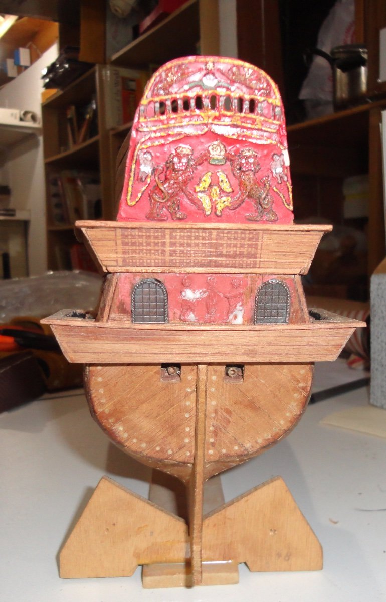
Great drawings, Waldemar. It was obvious to me (in light of your previous comment) that they are of the stern on the 1628 Vasa - as I'm trying to make the 'old' (first edition c. 1970) Billing Wasa (spelling used then for the kit) more like what we know now is the actual ship. The work done in restoration and scholarship in the intervening decades is remarkable. I note the lapstrake exterior planking for the higher portions. A challenge to do at 1:100, I'll cobble what I can for my own satisfaction.
-
I get the need to stone the deck, but didn't know that it was a daily task. The effect would have removed small splinters that might have been forming - to the benefit of barefoot sailors. Yet the process does involve abrasion, and the topmost wood fibers are worn off - reducing the thickness of the plank by a few thousandths. I'm not sure of the starting plank thickness (a good question ... 1 1/2" ? 2"?), but repeated abrasion would inevitably wear them thin enough to compromise their function. So my question is, how often did the decking need to be replaced?
-
Wasn't there more weather deck behind a free-standing forward cabin (apart from the dog runs overhead) and a smaller stern cabin?
-
Ahoy (after time to make all 6 gazebo tops)! Each side has three different sizes per the position they will occupy, and I realize that there has to be a curved roof over the galleries as well. Heavy demand from the hospital I work for as a Pharmacy Tech (due to short staffing) plus an influx of orders for Colonial Re-enactors (from the retailer) force me to sideline modeling for the time being. Yeah, something similar happened last year about this time. Anyway, once the balsa roofs have been carved, fitted and planked with the turrets - I'll take some photos and post. Meanwhile, I just love looking at many of the builds on MSW ... a source of inspiration and helpful tips. All it takes is a bit of searching and patience to find out just about anything about ship modeling. Johnny
-
Hairy/fuzzy rigging thread
Snug Harbor Johnny replied to The Gimps Chimp's topic in Masting, rigging and sails
So what is the RATIO of glue to water that you used? 1:4 1:10 ? This has got to make a big difference as the more concentrated the 'stiffer' it might make the rope. I do like Titebond (or any similar aliphatic resin glue) - especially in Winter (like now) when the relative humidity in our home is VERY dry. Bits of wood I glue with it 'grab' quickly and there is a partial cure in 30 min or so. Letting a blob of glue set on a paint stirrer as I work has some of the water in the glue evaporate to provide a 'thicker' glue even better to use for a 'quick bonding' effect. The same effect can be had if one leaves the top off a glue squeeze bottle for a couple days - then all the glue in that bottle gets more viscous. Putting the top back on stops the process from going buying what is desired. The thinner the glue, the more 'work time' for re-positioning. But if you pieces have been pre fabricated and test fitted already, who needs all that 'open time'? -
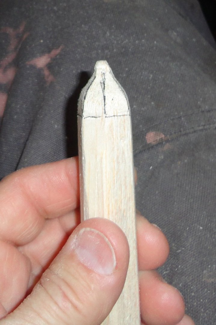
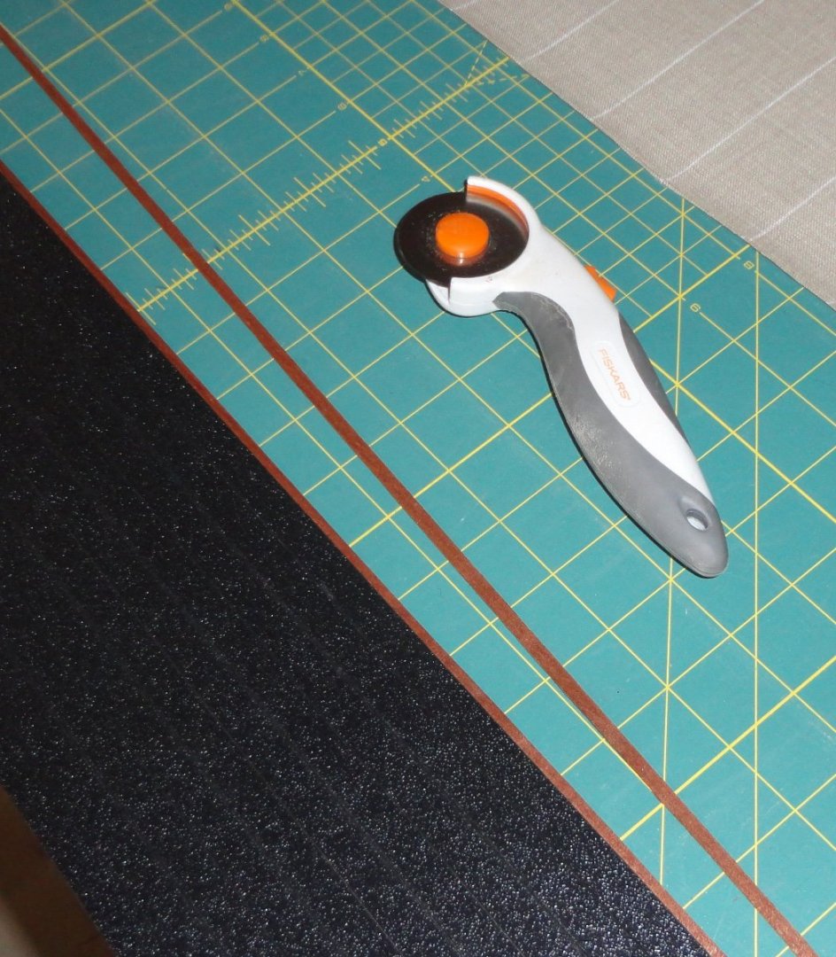
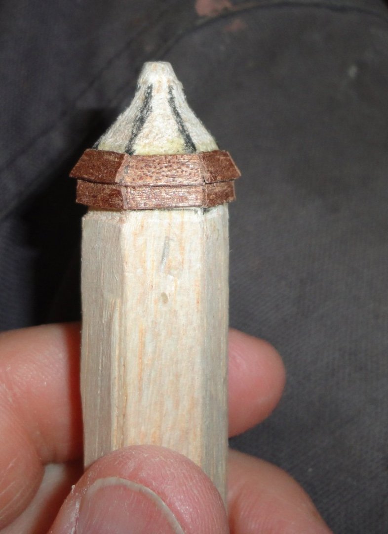
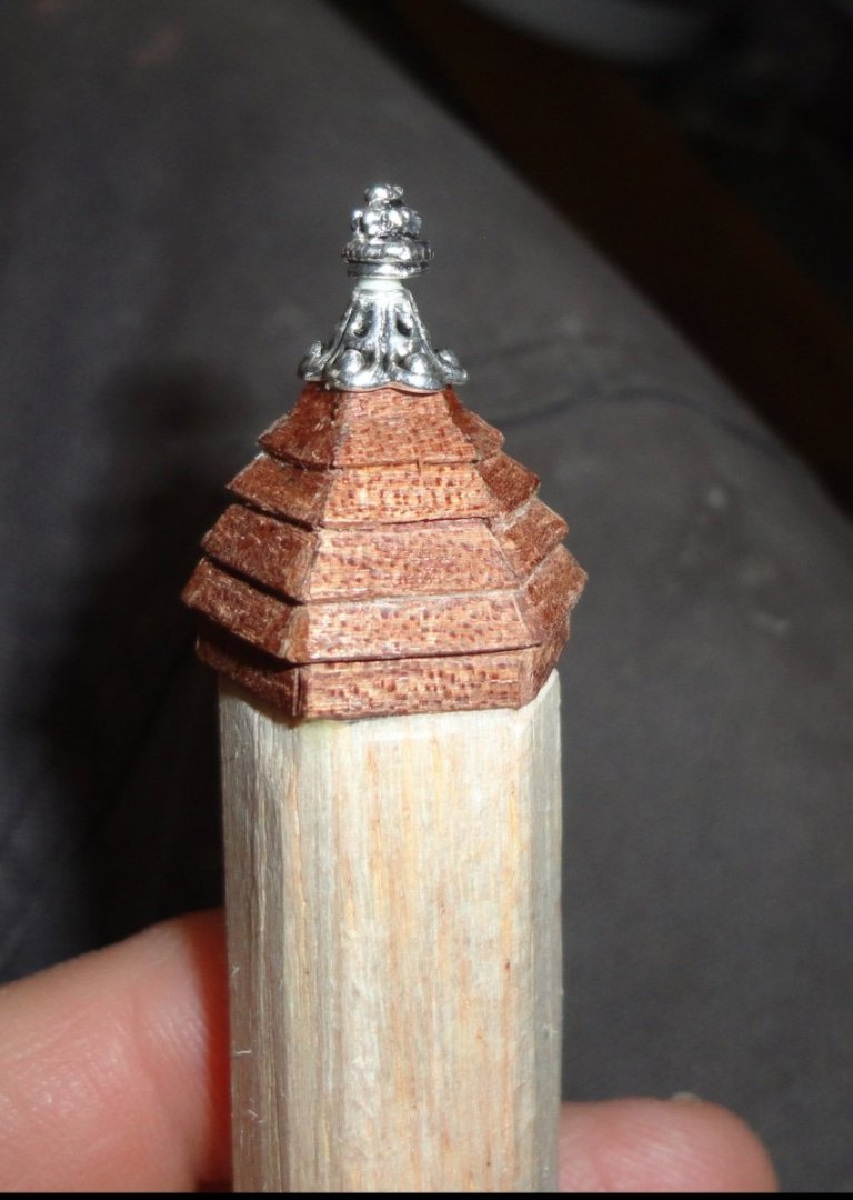
Some thought was given on how to proceed with the cupolas ... Some kits have turned wood to merely glue in place, and some builders have flattened facets on the cylindrical turnings so that shingles can be glued on. I'm trying to 'work smarter - not harder' and took a 3/4 inch piece of balsa stock and used a plane to shape the corners off to make hexagonal stock. Since all the grain is running lengthwise, it was easy to start whittling the end into a hexagon-cupola shape. Of course as one cuts into the stock, the grain becomes more like end-grain - so I used a mini sanding drum on a rotary tool to grind out the 'shoulders'. There first picture shows the stock (easy to hold onto and work on) with the shaped end - I marked the edges to make them easier to see. The illustrations below represent the steps to get from point A to B. No instructions here, so one must plan out each phase as one goes. I cut a thin strip of mahogany veneer to use for shingling the dome on its flat faces. The dry sheet measures 0.027" (nominal 1/32), so can be cut with a rotary cutter on a cutting mat (normally used for fabric. I'll have to change to a new blade before going back to textiles as it had likely been dulled a bit - but it was already overused for the original purpose.) At 1:100 scale it represents 2.7" thick shingles - a bit thick, but that's what I've got to work with. For the 1:75 models, it would correspond to about 1.9" planks - not unreasonable, considering the size of the warship. I did think of a 'colored' wood other than mahogany and walnut that is easy to find in the U.S. - heartwood poplar, which is light brown and oxidizes to medium brown over time. One could cut planking boards off the edge of poplar planks found where lumber is sold - once the light colored sapwood is trimmed. The lighter wood can be used for decking. Photo 2 shows the rotary cutter. Photo three shows the first two layers of shingles glued on with ordinary wood glue. I find that aliphatic resin glue 'holds' fairly quickly, but still has plenty of time to re-position or adjust parts being glued. The shingle stock (strip) is held up to the work piece and marked with a pencil for each piece. The part is cut off with an X-Acto knife and glued. After each time around, I let some time go by (what, 30 minutes) so the hold is firm enough to lightly file or trim. Curing takes longer, but I don't have to wait that long. Once I got the 'hang of it', I started cutting the shingles by angling the blade a little to get sort-of mitered corners. Now for the very tops, I found jewelry fittings at a local craft store - a 'bead cone' to glue on first, and a decorative 'head pin' to simply stick into the top. The pin was not hard to push into the end-grain of the balsa underneath, but a drop of glue was an added precaution. The cupola can be sawed off the stock with a fine saw - then a new cupola can be built. I have to make 5 more, and each will turn out a little different. Each will be tried on various places on the model to see what looks best. There can be further trimming to suit, and I still have to make the planked roof sections that go between the turrets. I'm definitely influenced by my late father, who started with model ships but switched to aircraft. He was really big on flying RC models - which were powered by gas engines years ago (now battery powered motor are the thing due to noise and pollution regulations). I picked a couple of small models from his belongings (my brother got the only remaining ship), and his craftsmanship shows. He had more skill than I, yet persistence and a relatively steady hand can still produce acceptable results in many applications.

-
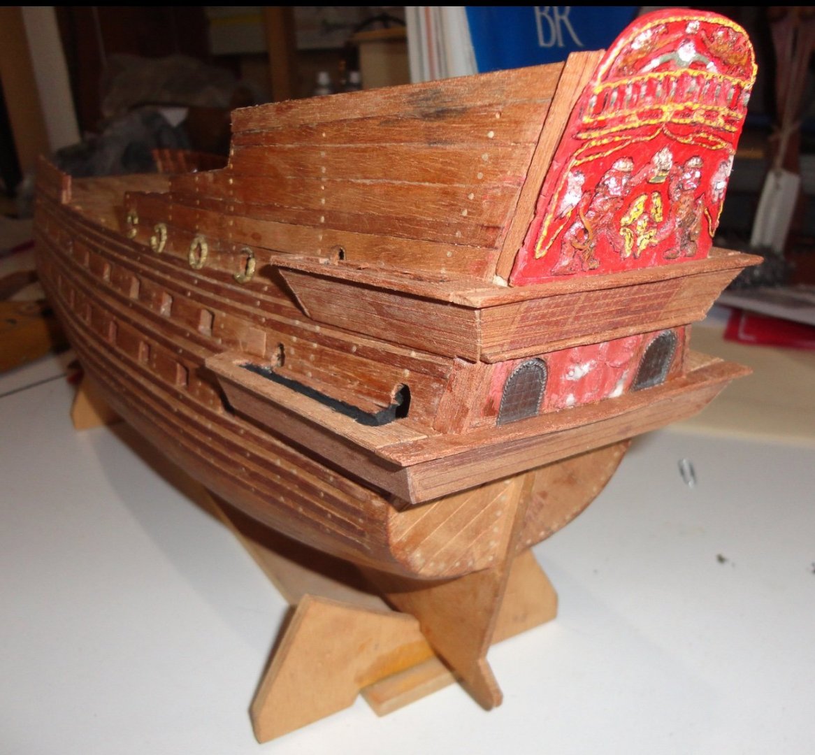
The lower galleries are now planked like the uppers - two access doors were drilled, but are note likely to be seen once the gallery covers and copulas are added. The second photo show that I was able to add some upward curve when seen from astern (didn't think of that on the uppers). As noted before, the job is to come 'closer' to the original, but there will be unavoidable inaccuracies due to the limitations imposed by the circa 1970 kit in 1:100 scale. Yeah, the stern geometry is off - and there will be missing elements, but it should be identifiable as the Vasa. Some pre-painting will be done soon before the gallery covers are fabricated. The third photo shows the installed viewing openings that will serve as a base for the gallery tops. The kit rudder (marked as part #55) is of plywood, so I glued some mahogany strips together and will cut a new rudder. There is a box of fittings from another kit that I've picked some hinges for the rudder. The paint stirrer is used to mix epoxy on (when used), or to hold a blob of titebond glue that is then applied with a small stick. Otherwise, a finger dab of glue can be put on some of the pieces. Fair sailing !


-
'Looks fine. Sworn testimony from deSilva (a Portuguese navigator Drake had on board from Brazil to the other side of Mexico) indicates a broadside of seven guns on each side - and period depictions of Drakes 'Caribbean Fleet' show 5 on each side on the weather deck (like your plans) plus 2 on each side of the quarter deck (presumably smaller guns) - just like many French race-built galleons that deSilva attested the Pelican (Golden Hind) to be. That left 2 stern guns and two bow chasers.
-
'Love your build. I'm no planking expert, but what is not seen in the final version should bother anyone. One should build to suit ones self.
-
Rob, the most concentrated isopropanol commonly available is 90%. I presume the 10% water content has no significant effect on the process, or is 100% possible to get?
- 444 replies
-
- 2
-
-
- Cutty Sark
- Revell
- (and 2 more)
-
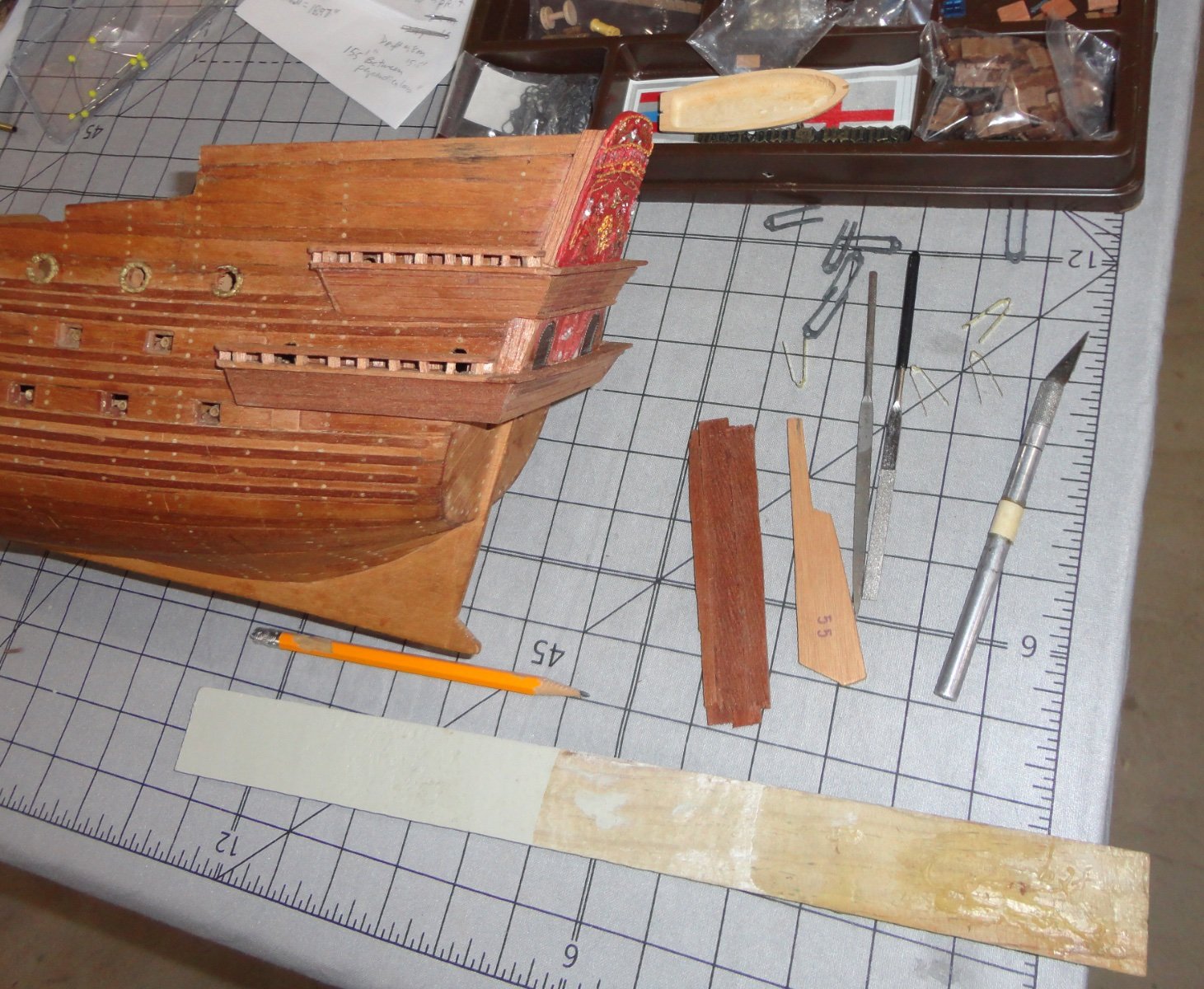
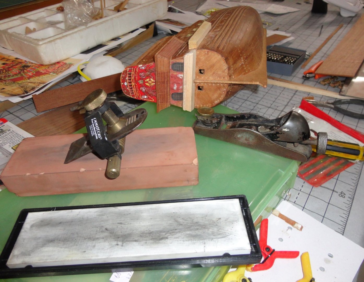
Thinking about the best grain orientation for re-sawing mahogany planking stock ... If one has a perfectly quarter sawn board (normally 3/4" thick in the U.S.) where the grain seen on the face runs parallel with the length of the board (one can always plane the edge to make that edge get parallel with the grain lines seen on the face), then cutting thin stock off the edge should provide the best bend-ability. The dots on the face of the planking are the 'rays' in the wood seen on-end. When cut at other angles, the rays present oblong to linear markings on the plank face. There are many books on woodworking and understanding grain, cutting stock, etc. Back to the model, I took a picture showing a number of things. Because the Cherub molding on the piece removed from the back broke, I glued the pieces to balsa substrate and made repairs her and there. I scrounged rear windows from another old kit I use for supplies, and realized that they should be recessed to become flush - since military miniature figures will have to be added later on either side of the windows. The rotary tool was used with a milling bit (hand held, I had to be extra careful not to remove too much material). Balsa pieces were glued below to provide the substrate for the lower gallery, and I used a low-angle plane to shave off the balsa on the stern - since the grain was oriented across. The blade had to be quite sharp, and you can see the Veritas holding jig to assure the bevel is even on the blade - which is on a Japanese water stone (here shown dry) 1200 'grit'. There is a tiny arrow on the end of the brass knurled cylinder if the sharpening jig that is shown pointing 'up' in the picture. When the bevel is cleaned-up, this arrow is positioned pointing 'down' (there are detents on the barrel of the jig) to create a 2 degree micro-bevel. The white stone at the bottom is a super- fine (6000 I think) finishing stone for the micro-bevel. Then the blade was remove and the back worked flat on the finishing stone. Stropping on a piece of thick leather was a final step in getting a razor sharp edge. Then the low-angle plane could shave off thin curls of wood going with the grain. I suppose that it could be used to taper planking as needed when doing planking. I've heard that miniature planes may be available. In the photo, you can see the side piece of wood I'm shaping before gluing to provide the substrate for the lower side gallery.
-
So very nice HakeZou ! - I will refer to your build (and others) when I get around to this project. I love the way you've put in decent steering tackle on deck astern. Your addition of hanks on the pin rails is practical and attractive. You have made great recommendations for enhancements, and one could add to them with: Install chainplate from the lower deadeyes to the hull; Use custom rigging rope made on a mini rope walk (done at home or purchased commercially) to limit 'fuzzies'; Copy the sails on finer material ... but even 'out of the box', Endurance is a fine intermediate kit. Fair sailing, mate ! Johnny
-
... A site I'll revisit as I cobble my old build into better conformity. Yours is looking good! Johnny
-
Metal bashing
Snug Harbor Johnny replied to michael mott's topic in Metal Work, Soldering and Metal Fittings
You are a machinist/builder par excellence ! My hat's off to you, sir. -
No picture in this post, mates - but comments on how I'm working with the mahogany - often found in older kits. Different stocks behave according to how the grain ran when cut. Thin veneers can spit, and planking stock can be weak in a certain direction where the grain runs. Handling the various pieces can reveal which are better to bend. The color van vary, but can be pretty closely matched. I'm talking about Honduran mahogany exclusively (there are other types like Philippine and African), and because of the present limitation on supply and high cost, one does not find find it much in new kits. It is most attractive for hulls that are mostly unpainted, since it does not need staining at all. The color can darken slowly with age, presumably to additional surface oxidation. It does not show glue from squeeze outs very much if aliphatic resin glues are used, and I find that excess can be scraped off in most cases. Because there will be no finish applied, the slight presence of dried glue is not an issue in my opinion. But if lighter woods are used that need finishing, any area affected by glue (not sanded away) will not take the stain and really show-up. I find that gaps or mistakes with mahogany can be remedied by fitting a suitable scrap and glueing for later re-cutting/sanding. The repairs blend well for the most part. Walnut is another dark wood needing no finish, and the same principles apply - except that wayward glue can show more on the darker walnut. Availability is good, for there are a number of species widely grown around the world. Perhaps working with colored woods on furniture projects over the years have endeared them to me.
-
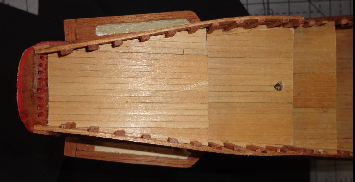
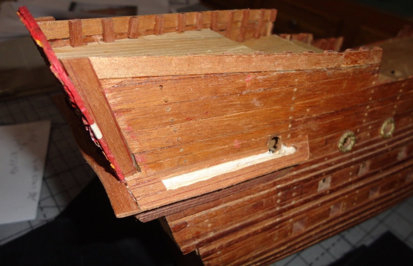
The next step was done on both sides - since someone looking closely (cringe) when the top part of the walkways are built will be able to see a little inside the 'gap' between the bottom and the top components, I decided to use a rotary tool to mill away some of the basswood/balsa underlayment where the walkway would be - as well as cut an access door in the side of the ship. I'll pain the light wood black, so it didn't have to be routed out very deeply, as the viewing gap (for any aboard to see out of) is relatively small, thus it restricts the angle that a human observer of the model will be able to peer inside. Below is a top view. A view from the side shows the little doorway cut into the hull. The wood across the stern was given a little undulation as seen on many models. There is a little improvising as each step is accomplished, since the alterations to the 'outdated' old kit have to be done without instructions ... but all the great builds and other museum information help in the process. And indeed, there are differences from model to model - as the finesse and detail seen on the original ship in Stockholm are challenging indeed.

-
Guterman thread is found (SE Pennsylvania, USA) in sewing or many quilt shops, and it has good strength in the sewing I've done. But I like Metrosene (made by Mettler - also a German company) even better. I'll try it for rope making - noting that the full-size demo rope I make at Colonial craft fairs on my hand-cranked gears rope walk has three strands of common jute cord on each of the three spinners that will make the three strands of the rope. When I get round to using the Rope Rocket (thankfully drill powered), the layup will be the same, as I haven't dabbled with any four strand rope (those using antique rope spinners with four hooks have that as an option). Different thickness of rope require different thicknesses of cord, and in the case of model ship rope that means different thread weight. The finest I can find is #80 in cotton, and it easy to break - but would make the thinnest rope, and would be reasonably strong once made from all the strands together. #60 and #40 will be progressively thicker. There are other weights going down to buttonhole twill.