Beef Wellington
-
Posts
2,249 -
Joined
-
Last visited
Content Type
Profiles
Forums
Gallery
Events
Everything posted by Beef Wellington
-
 Catching up a bit, love the treenails and nicely done on the molding strip. My feeling is that impression of the detail, rather than absolute accuracy, is 90% what the eye sees, and my eye likes what it sees 😊
- 574 replies
-
- 4
-

-
- cheerful
- Syren Ship Model Company
- (and 1 more)
-
Really nice Carl, missed the home stretch but awesome result!
- 292 replies
-
- 4
-
-
- g class destroyer
- trumpeter
- (and 4 more)
-
Really nice work there Martin. Would love to know how you cut the notches so precisely? The headworks all looks so easy when completed, but clearly that is not the case, and you've done a wonderful job there. Nice photos, I'm curious, is the first photo in the Neah Bay area of the Olympic peninsular?
-
Lovely planking BE, can only look even better when sanded down. Nice work on the garboard planks, look tricky to shape, and I can see the advantage of the having the upper planking in place to help provide perspective.
- 574 replies
-
- 2
-
-
- cheerful
- Syren Ship Model Company
- (and 1 more)
-
Congratulations Nils on completing such a fine model, wonderful sailwork. You have a true artists eye to have everything come together in such a way, well done indeed. Looking forward to next project!
- 692 replies
-
- 5
-
-
- eagle of algier
- chebec
- (and 2 more)
-
Do you plank on top of the bulwarks or are those the final surface? - not seen it done that way before. Looks nice and neat Bob.
-
Love the KGV, remember building this kit a number of years ago. The camo pattern I went with was definitely different so assuming was a different time period. Looking forward to seeing the PE.
- 405 replies
-
- 7
-
-
- tamiya
- king george v
- (and 2 more)
-
Hi Stergios - my apologies, I used the wrong words in a hurry. The bowsprit does need to be fitted as you describe for the main, preventer stays to be completed. There is also a fair amount of standing rigging on the bowsprit that I would suggest doing before you do that. I think I actually did the bowsprit standing rigging before actually starting the mast standing rigging working from the stern. What I meant to say above was that its not really necessary to attach the jib boom at this point - makes manipulating the model much easier as the jib boom seems to be an accident waiting to happen. Good Luck!
- 1,144 replies
-
- 1
-
-
- snake
- caldercraft
- (and 1 more)
-
Count me in on this OC from here in, interesting to see how this comes together and how you approach the painting. Nicely done so far.
- 229 replies
-
- 6
-
-
- trafalger class
- airfix
- (and 2 more)
-
Bowsprit standing rigging does not interfere with the other masts - I also started from the back.
-
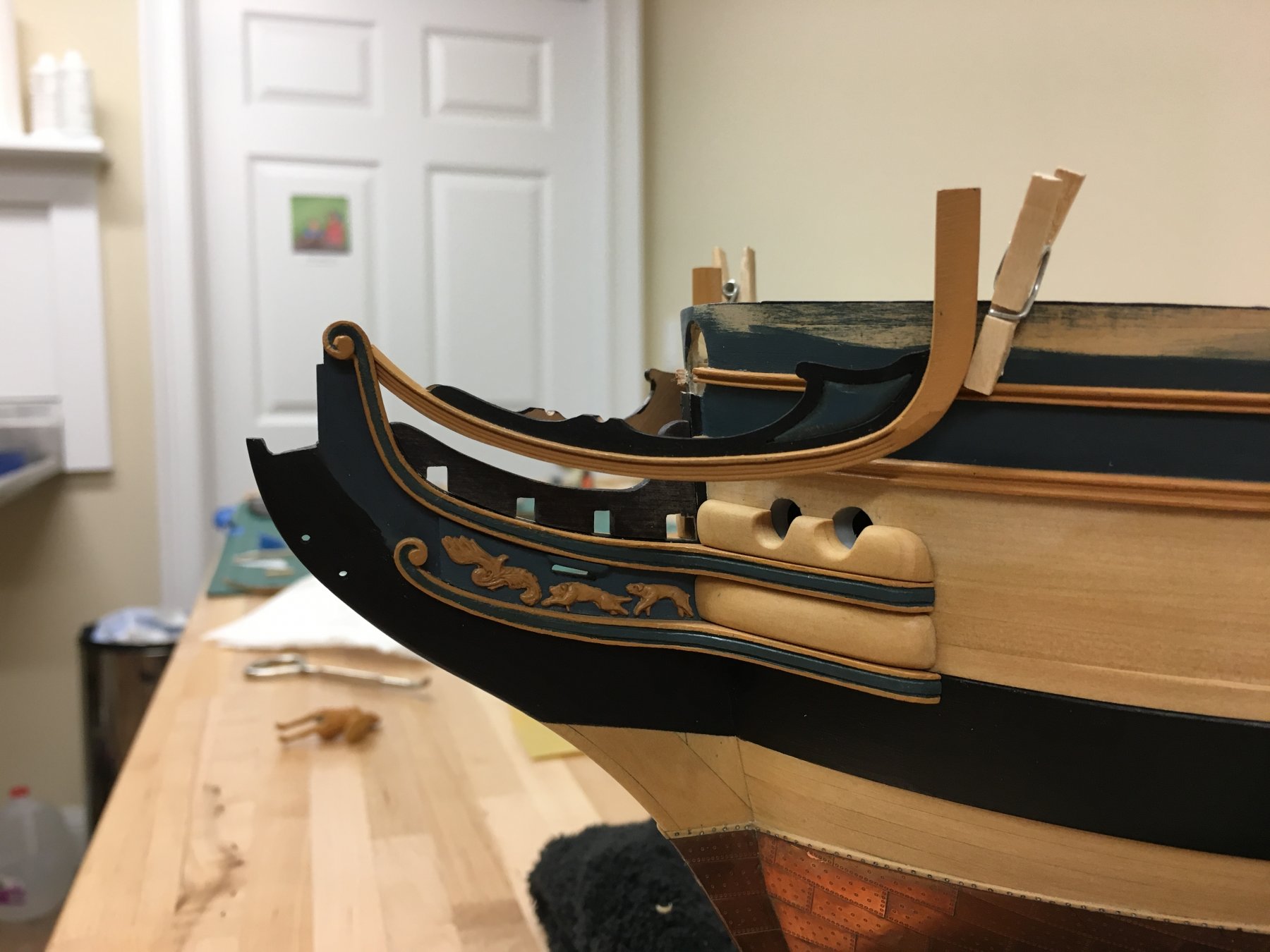
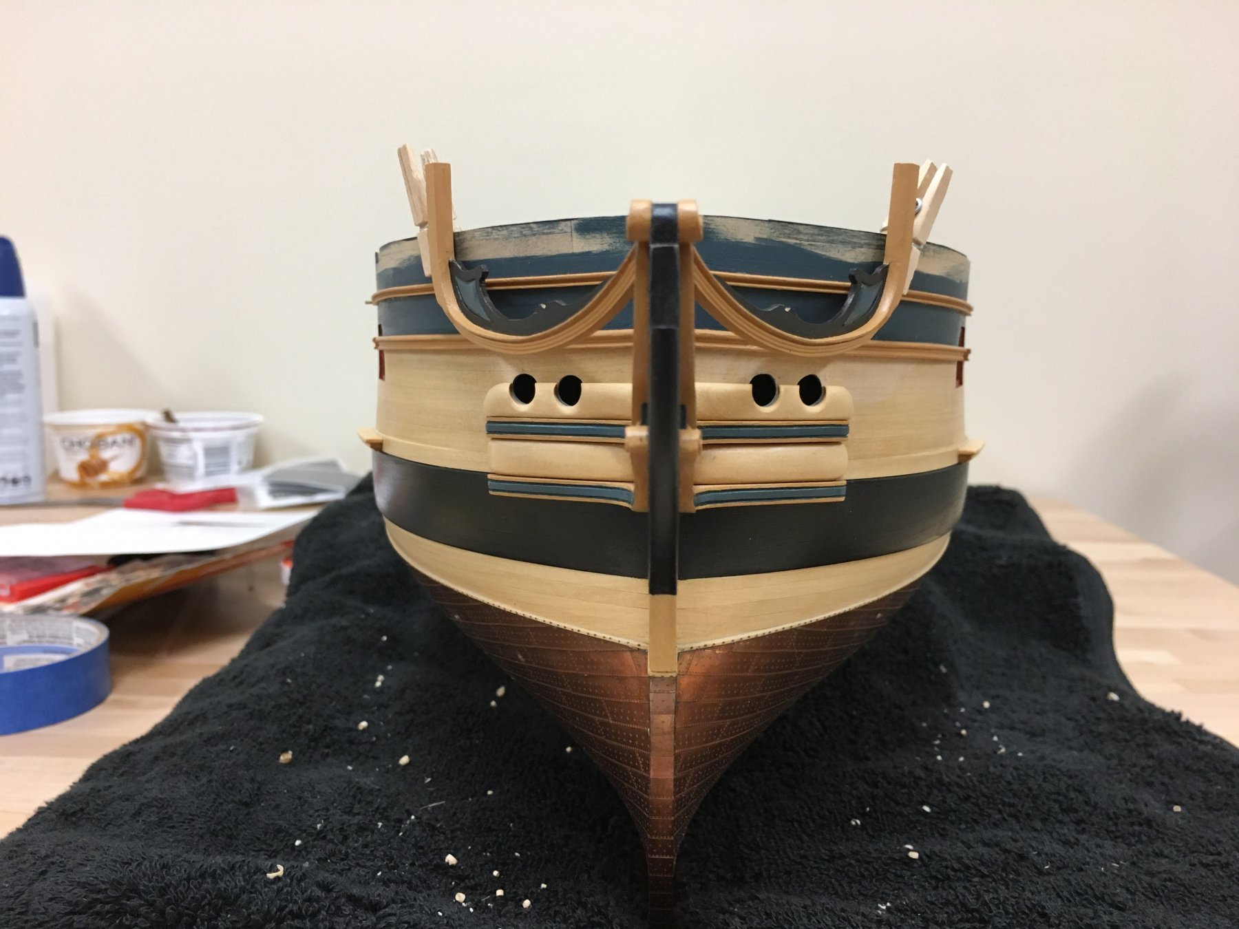
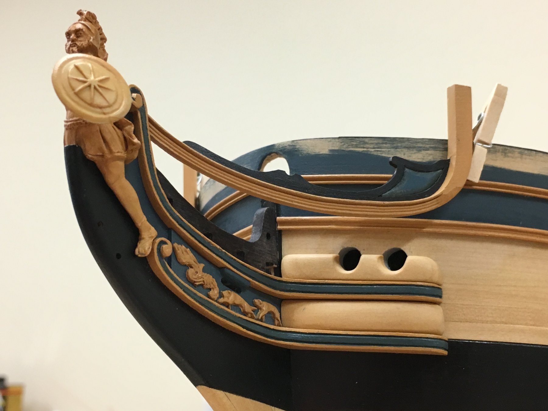
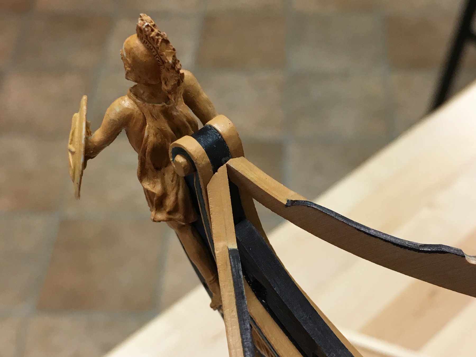
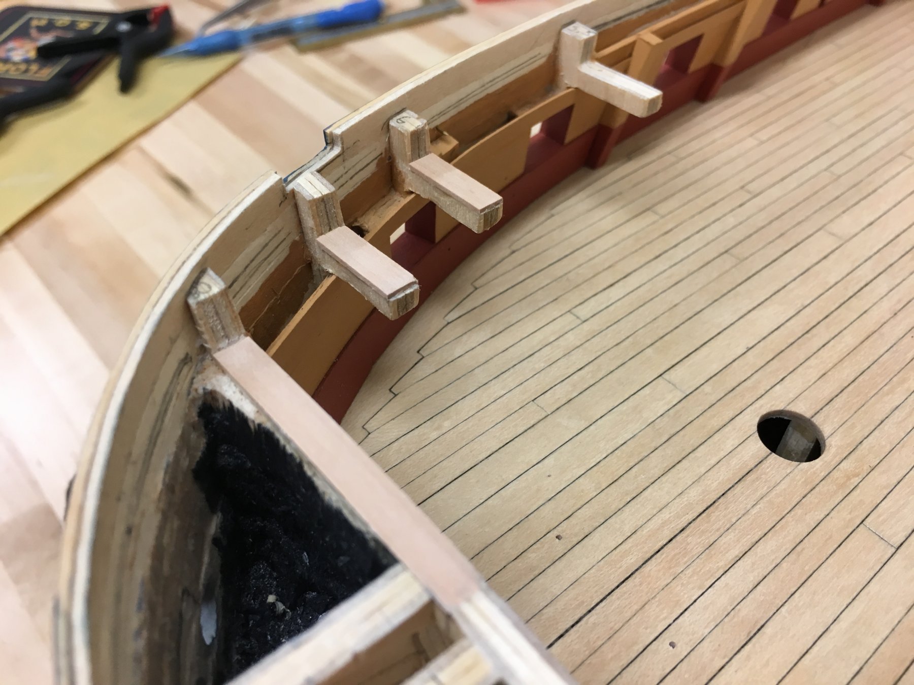
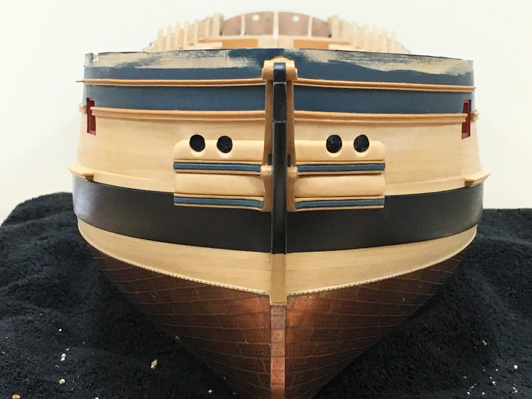
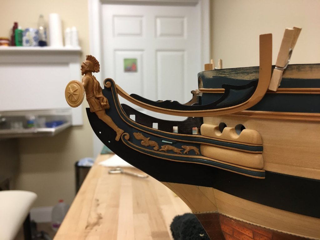
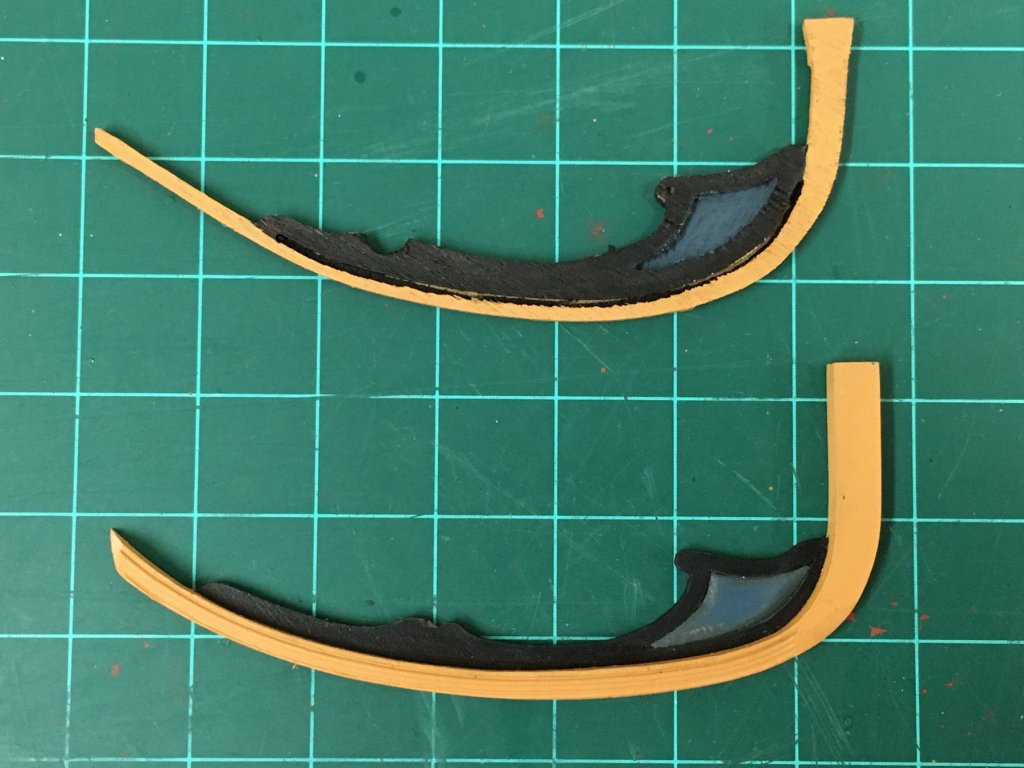
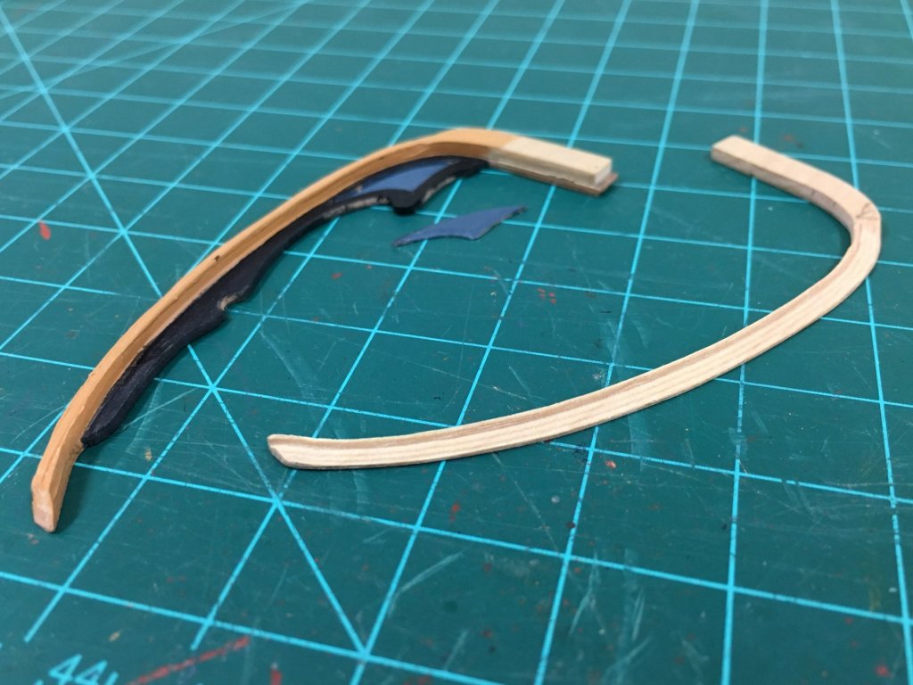
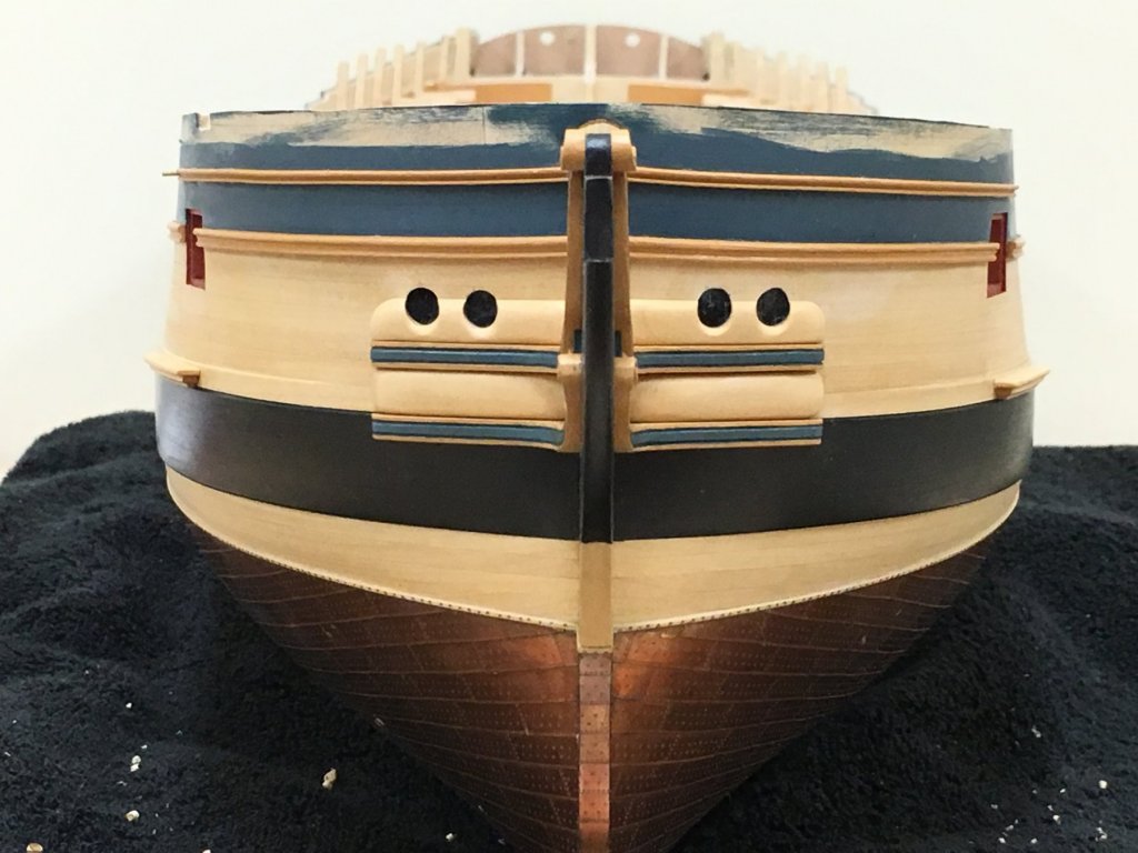
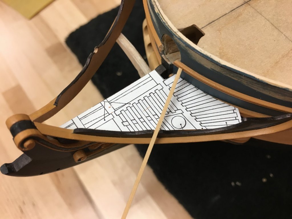
First off, thanks everyone for the likes and comments, my apologies for not responding sooner. I haven't been able to keep up with everyone else's builds as much as I would have liked. Been tinkering with a number of items that I want to get a head start on hopefully avoid pitfalls later. I'm leaning toward getting as much work on the hull planned out or complete before the cannons get installed and the upper deck can go on - although that will still be a while because I needed a break from gun carriages. Trimming the bow height: Way back I'd mentioned that I took the approach to build the bows up higher than I would likely need to allow for the unforeseen. I have now shaped these to be much closer to where I think they will end up, less a little finishing. The bulwarks at the bow appear to be parallel to the whale, just like the rails, which was used as a guide. This was an exercise in reconciliation as of course various small (or not so small) errors have crept in along the way. This proved not too difficult, the only hiccup was found when dry fitting the deck, to ensure that the height of the bulwark is symmetrical on both sides, some shims were added to the top of some of the forward bulkheads. The error is unlikely to be in the kit cut bulkheads, but more likely a combination of small discrepancies in my positioning of the position of the whales, waterline etc. You can see in shots below the discrepancy in the height of the foremost gunport, this was a result of positioning the ports to be of equal height off the deck, which was clearly not fitted as well as it should have been. These add about .5-0.75 of height on the starboard side, but the very small 'twist that this will introduce will not be noticeable. The sheer rail at the bow has also been added. Headworks: Have been doing a lot of thinking about how to approach the headworks, clearly a rather challenging area. Frankly, the kit supplied parts are a little disappointing being rather grainy and splintery, with some questionable dimensions. The main rail seemed to be the place to start, and after a lot of experimentation decided to build this and the false rail together rather than in separate pieces - mainly because it seems sturdier, and less challenging as the false rail is rather lengthy and thin at this scale. The main rails were cut from 2mm castello, and a profile introduced using a scraper to simulate the various features of the genuine article. Curved, tapering shapes have to be the hardest to get right, especially with fine details and there were many time consuming rejects which painfully got me up the learning curve until I was happy. The AOTS side elevations were scanned and manipulated digitally to correct for the angle to get the appropriate shape. Caution! I think the placement of the slot for the boomkin is not shown correctly on the AOTS side profile, I adjusted this looking at contemporary models - the revised position matches closely with the kit part which does provide some comfort. The false rail was cut from 0.6mm pear sheet and 2 were laminated together. The panel section of the false rail was cut out carefully to be shaped later by beveling the edges before replacing back in place. First photo below shows a little how these were built up, with the first successful but discarded prototype, and a main rail that failed scraping. Second photo below shows the kit supplied part next to the one of the scratched final articles. Ignoring the quality of the wood (and to be fair, I made no effort to clean up the supplied parts), the AOTS plans suggest a subtly different profile curve, and a thicker main rail which looks too thin on the kit part. The head of the main rail was deliberately cut a little longer to allow final shaping once these are finally installed. These were then positioned with the head of the main rail vertical in both head on and side elevations. It was found that these were quite easy to keep in place using mini modeling clothes pins (scale replicas of the actual clothes pins used in actual ship construction ). Posting a lot of photos because I would really appreciate comments and suggestions from those more experienced with this to help me avoid fatal errors! Finally, to confirm the layout of the boomkin slot, a copy was copied and scaled from the AOTS diagram. This shows the tight proximity of the boomkin and seat of ease. The triangular gap at the rear of the grating behind the false rail screen is where I believe there should be another seat of ease. Again - I'm fumbling my way through this following the excellent TFFM book, so please do not be shy to point out errors and mistakes!


-
Lovely work Pierre, can't wait to see some pictures soon. Really is a fine looking kit, the stern looks particularly impressive, think some modern kits could learn a thing or two from this.
-
Looking really good Bob, great paint results and good choice on the veneers, the problem you identify seems endemic to precut kit parts. Turned out really well after your extra work.
- 421 replies
-
- 2
-
-
- caldercraft
- granado
- (and 1 more)
-
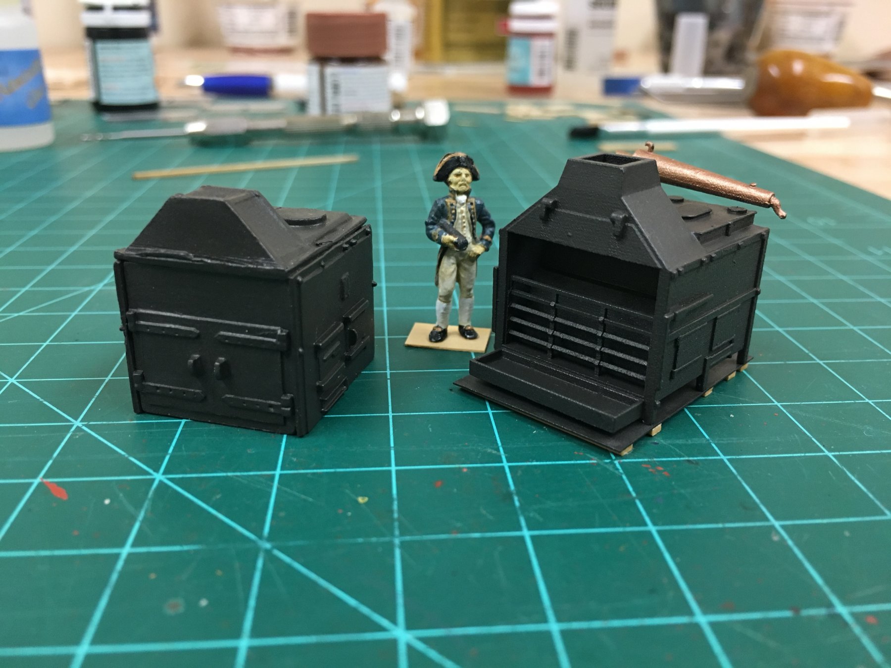
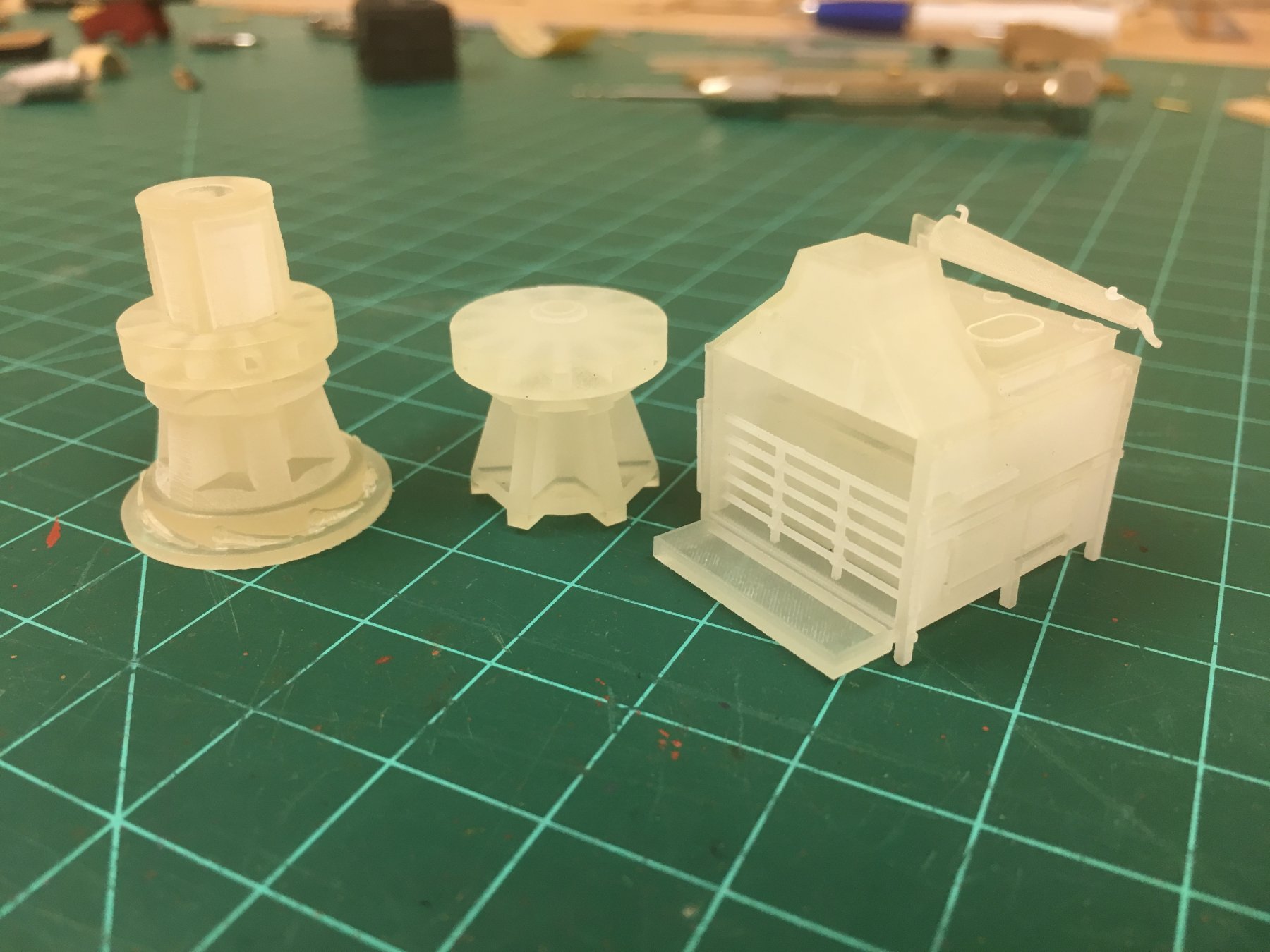
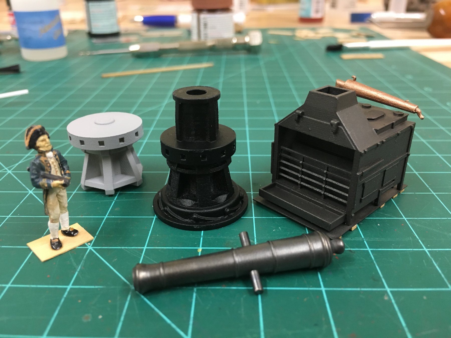
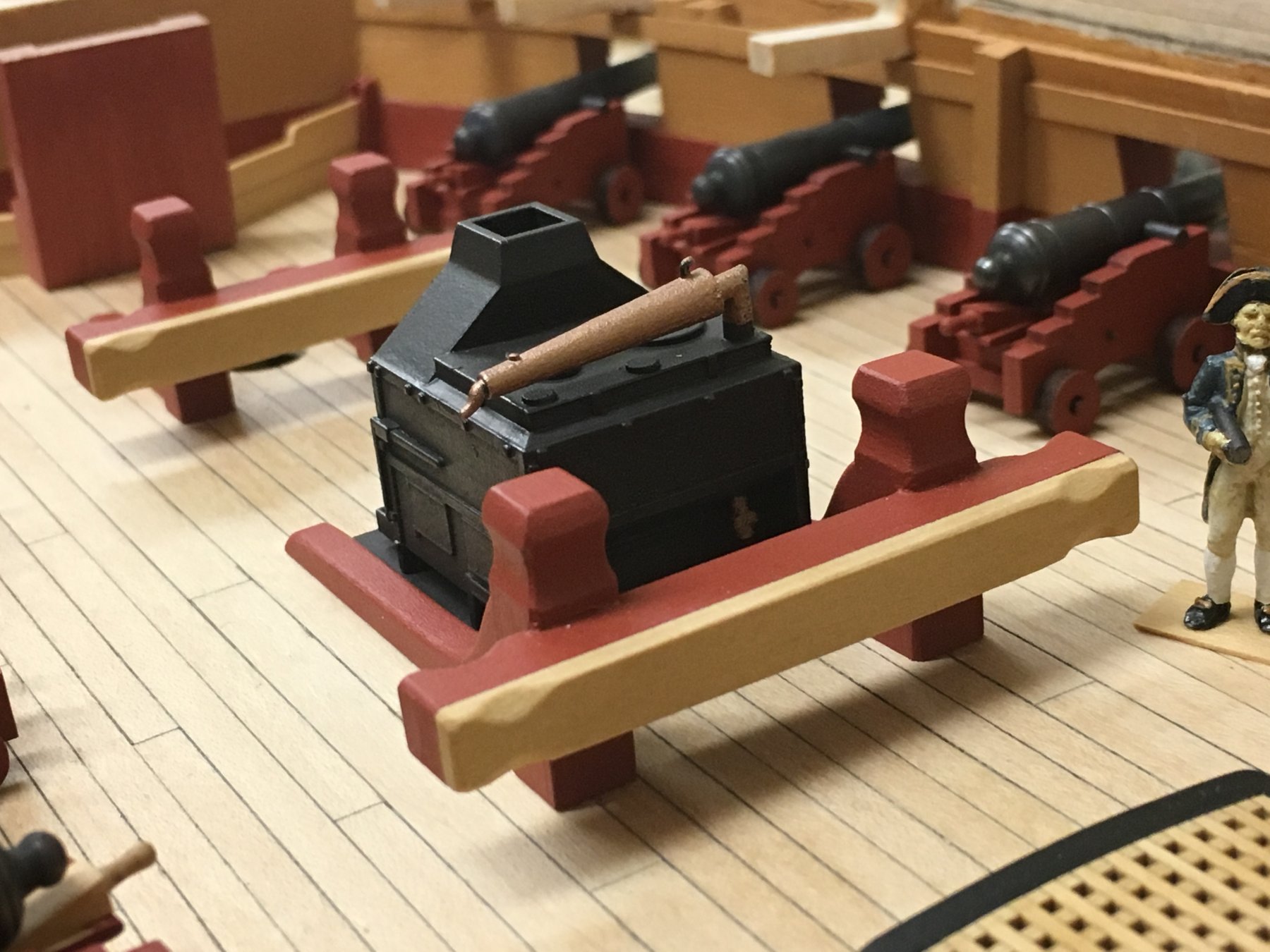
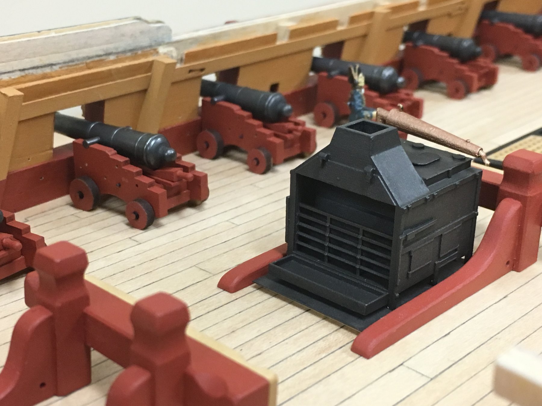
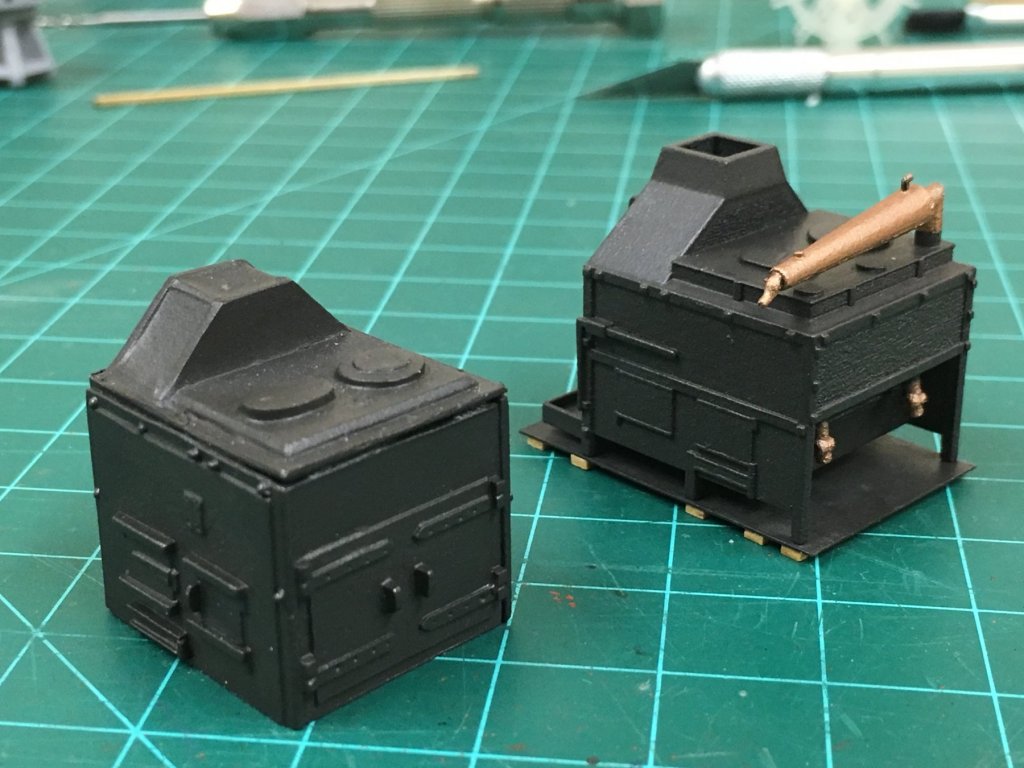
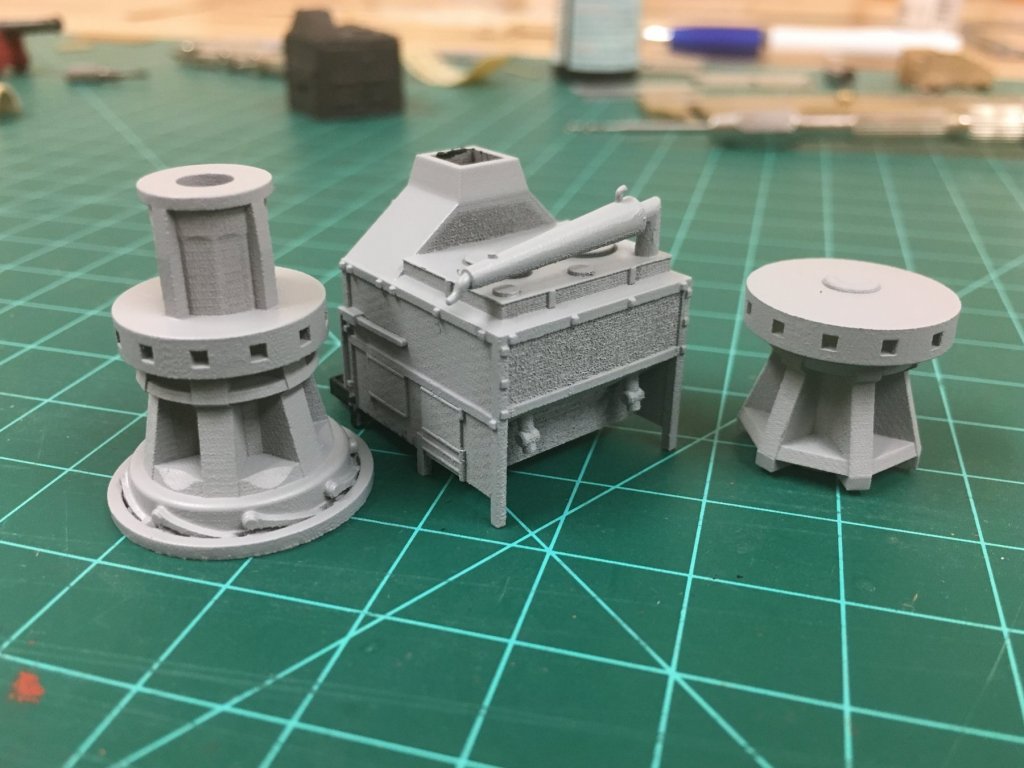
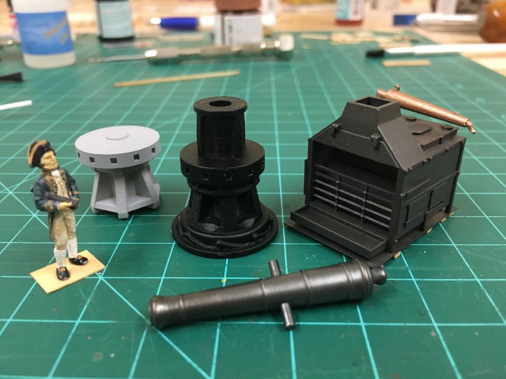
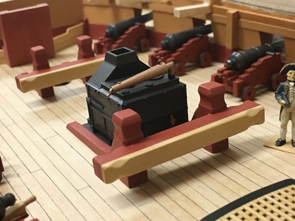
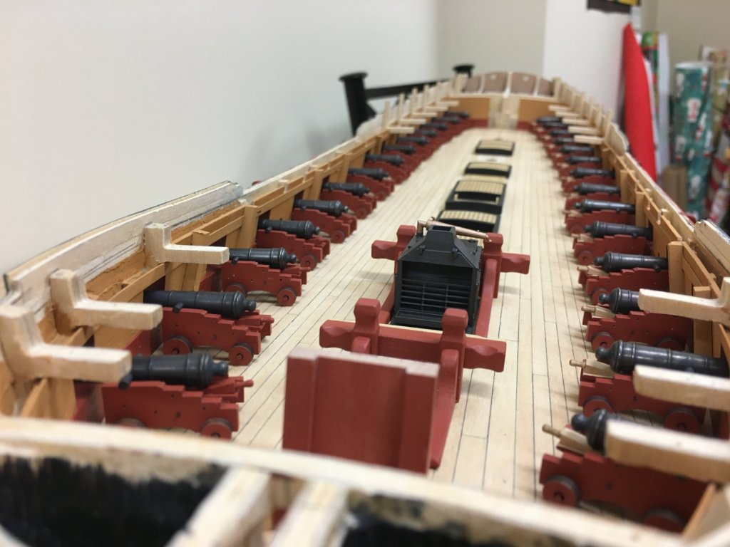
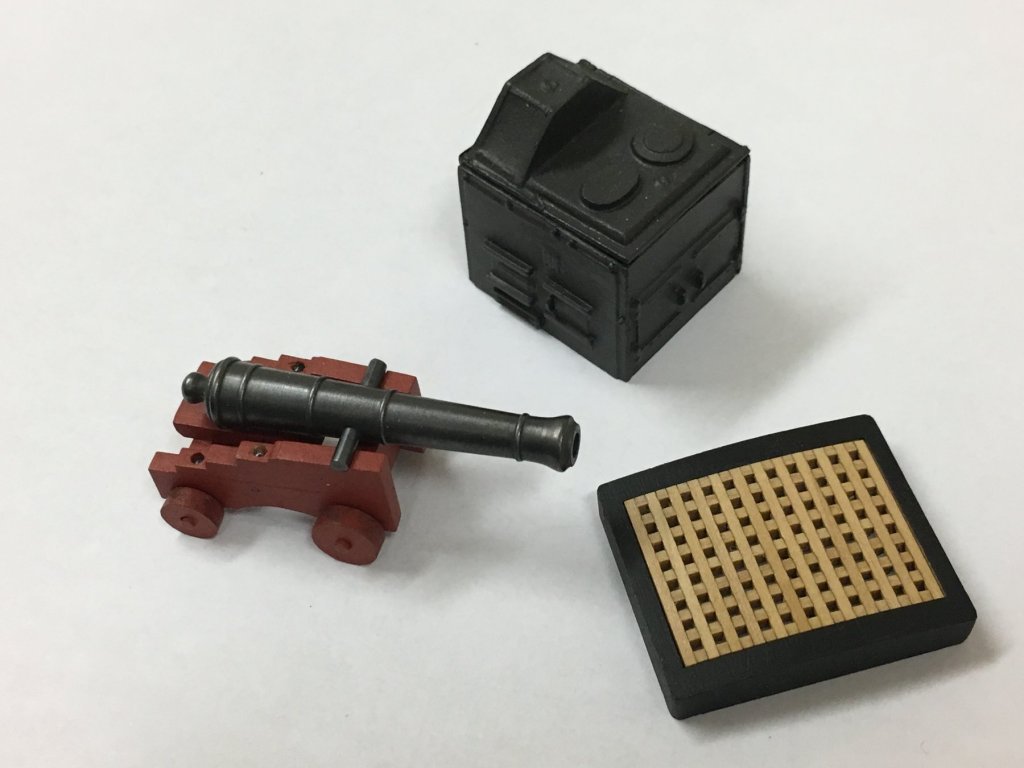
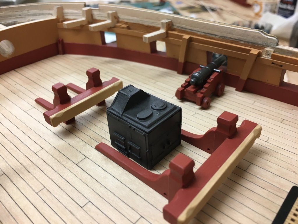
Thanks for kind words everyone, welcome back Nigel, and welcome Ian and channel. Mini update on a few things, think pictures are most useful. I saw reference to a 3D printing service somewhere else on this site (Shapeways.com) and specifically one of the 'shops' on that site Model Monkey, so wanted to give it a try. They offer a few items in 1:64 directly taken from the AOTS Diana book and offered to 3D print. You could browse for hours through all the items offered, but here is the most helpful link for 1:64 scale offerings, these can also be made in a variety of scales. (https://www.shapeways.com/shops/model_monkey?section=1%2F64+Scale&s=0) Intrigued I ordered a few items, stove and upper and lower capstans. Out of the packet, these are translucent and it recommended to soak these, brush gently with soapy water to remove oil residue and then expose to sunlight to chemically harden - I did 2 days. I ordered the 'Frosted Extreme Detail' which is slightly more expensive but apparently a more true print. With an initial coat of Tamiya arcrylic grey primer the surface texture is easier to see, and the layered structure is quite visible. I set to work on the stove and sprayed again with a matt black undercoat before finishing with the Tamiya Dark Iron. After a number of coats, the surface texture is less apparent and really only then in lighting scenarios from above that are unlikely in the finished model. I was reluctant to try any sort of 'sanding' as the material seems quite soft. With a little bit of extra work on the stove base (evergreen sheet) I think the result compares favourably to the kit supplied parts. Overall, the proportions look more accurate (as one would expect), and the front and rear of the stove much better represent the prototype features. I could easily see that someone could to get a better finish and detail some more but I'm leaving as is, at least for now considering what will be visible in the finished model. The other benefit is that this barely weighs anything, the white metal stove parts provided are really quite heavy and would need to be well secured. Considering the finish, I'm leaning toward using the printed lower capstan as this will only be partially visible, and provides a reasonably detailed proxy with minimal work. This will save some time to focus on other much more visible aspects of the build and I'm Ok with 'cheating' on this item. The upper capstan I'm less sure about, and will likely construct my own as I don't think the finish is up to close scrutiny. The bottom picture highlights this for direct comparison. The matte black undercoat on the lower capstan shoes direct comparison the "dark iron" and the way that this colour compliments nicely in my view chemically blackened metal (barrel appears overly shiny!). Luckily I did not need to rebuild the aft bitts as the stove fit perfectly - lucky that I'd used the estimated AOTS dimensions when these were built. In other news...work on the cannons continues slowly: these are all near the point for further detailing and hardware as structural elements are complete. Each has been allocated its specific location and in some case the bottom of the trucks reduce slightly to ensure good seating on the deck. Quoins were individually placed to help ensure all barrels form a smooth line when viewed from the exterior.


-
Looking really good Rob, definitely spot on with the "3-D puzzle' comment. Like the lettering on the upper counter, and the boxwood frames are a very nice touch. Your filigree came out very nicely as well, great stuff!
-
Looking good Paul. Its very hard to tell from photos, having experienced this issue myself, I concluded that to look 'right' the angle of the foremost pillar should be the same as the stern fascia when viewed from the side. The others then need to be parallel to these when viewed from the side. Of course that means that the sides of the lights themselves are completely different shapes. I'm sure others can comment more definitively on my purely visual impression.
-
Hi Bob, I've experienced the same problem. I'm sure thinners would work, but I've found using regular tap water can work just fine as well using a larger brush. Gives a much smoother surface with a longer dry time, of course you need more coats. Have you decided upon a paint colour? I quite like the Admiralty "Light Ivory" colour which is a little more subdued than plain white, but I'm sure there are other brands.
- 421 replies
-
- 1
-
-
- caldercraft
- granado
- (and 1 more)
-
HMCSS Victoria 1855 by BANYAN - 1:72
Beef Wellington replied to BANYAN's topic in - Build logs for subjects built 1851 - 1900
Great pictures, everything looks so fine and 'to scale', really nice looking model Pat!- 1,021 replies
-
- 3
-
-
- gun dispatch vessel
- victoria
- (and 2 more)
-
John, that's a really well executed authentic looking cannon and carriage, well done. The consensus seems to be building on the RB barrel, Syren carriage combo. I too had the same issue with the thickness of the stool bed causing the elevation problem with the quoin, I replaced these with custom cut 1mm thick parts which visually is not too different but your approach is much purer. My thinking was swayed I think by having 28 of the blighters to do...
-
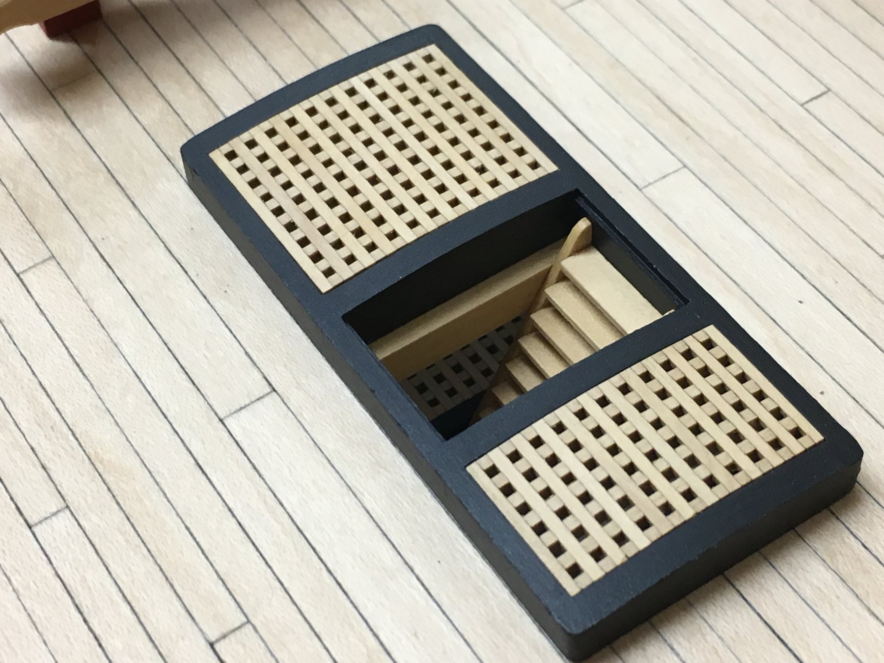
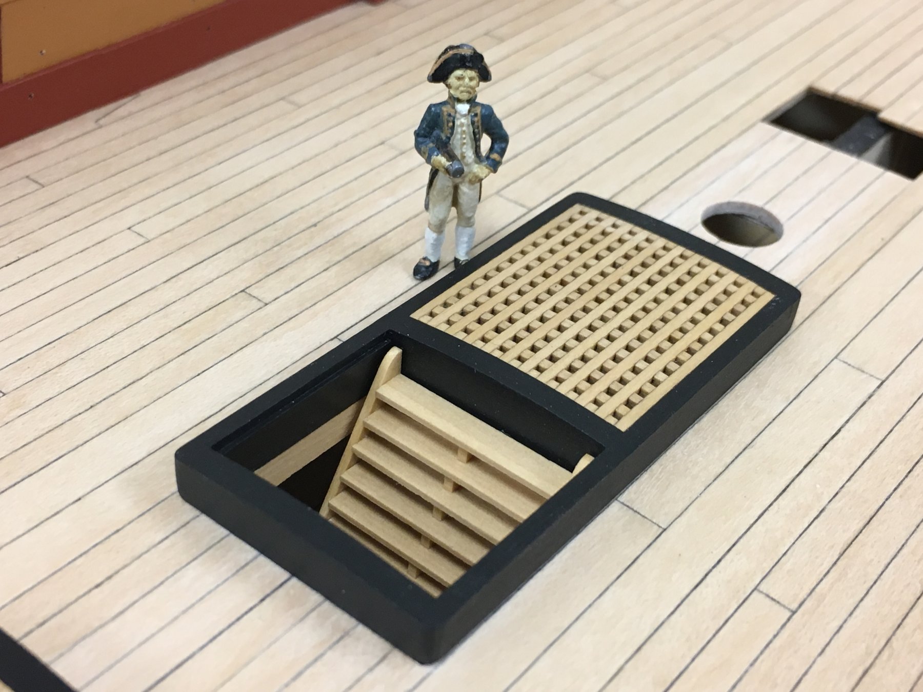
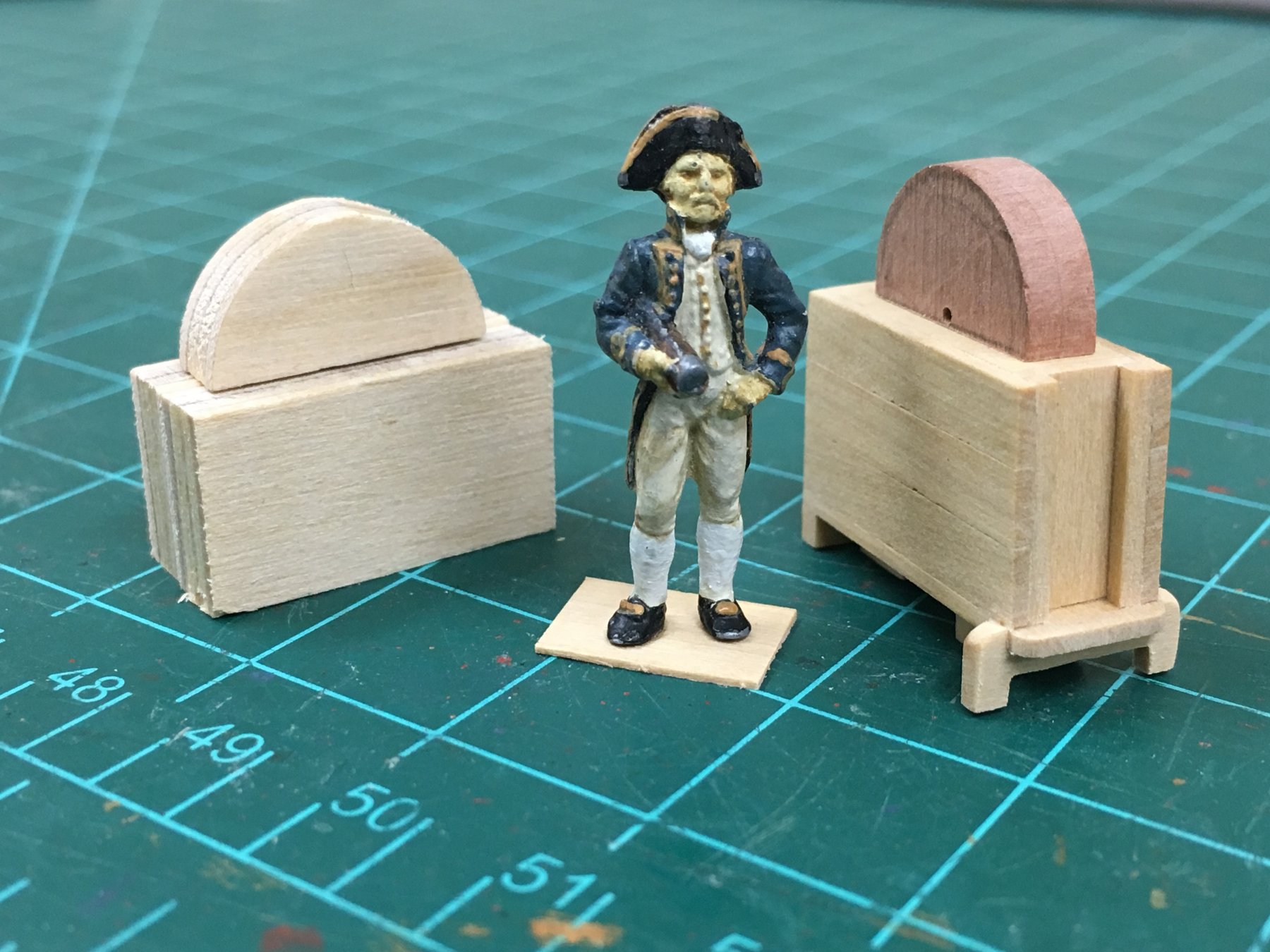
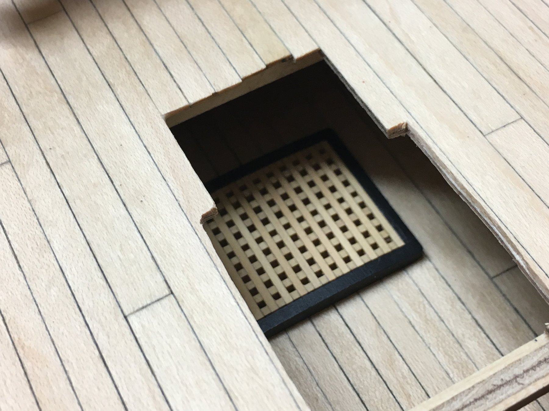
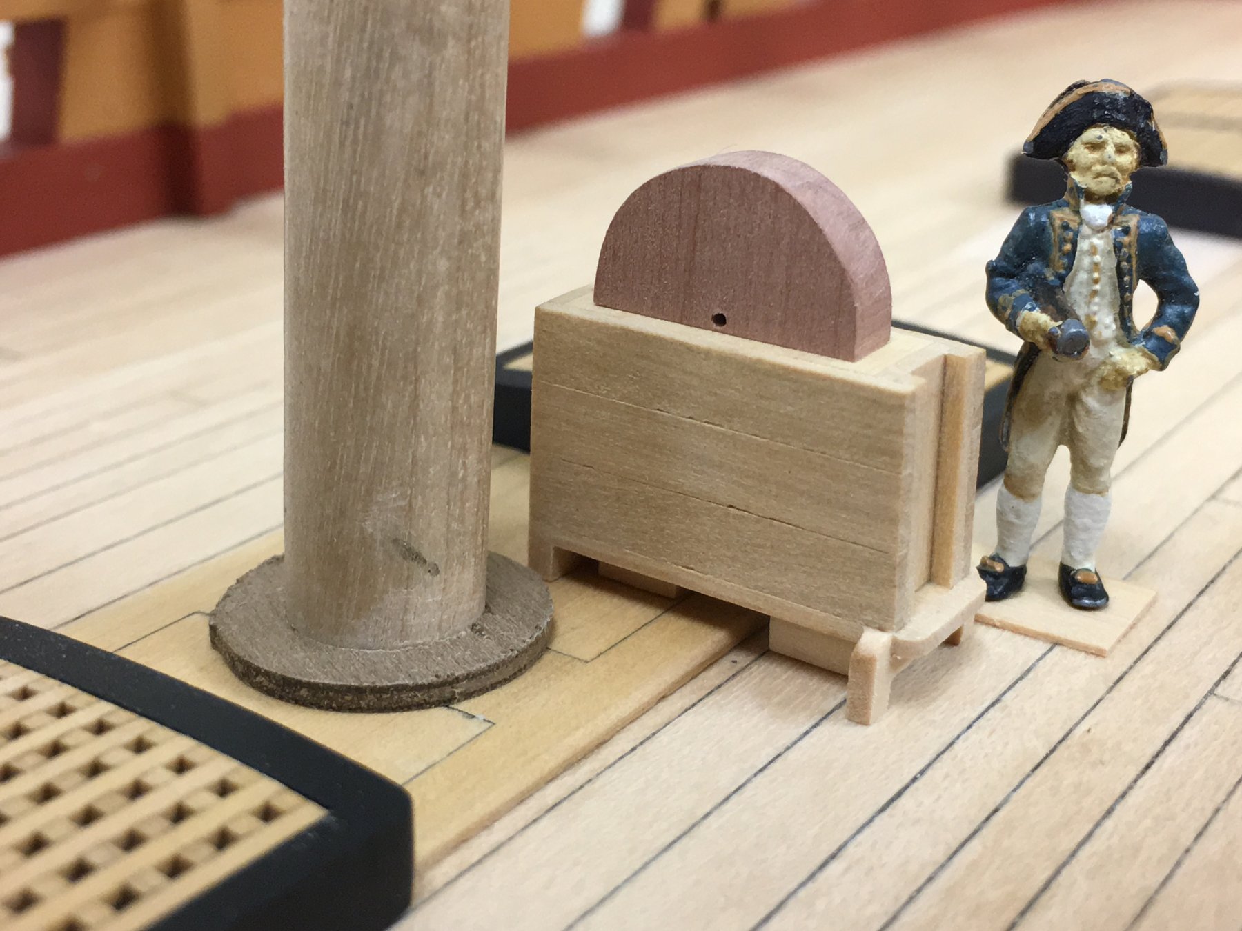
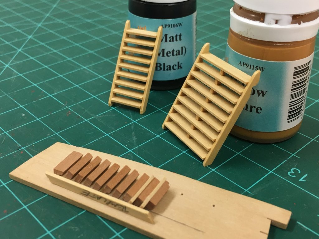
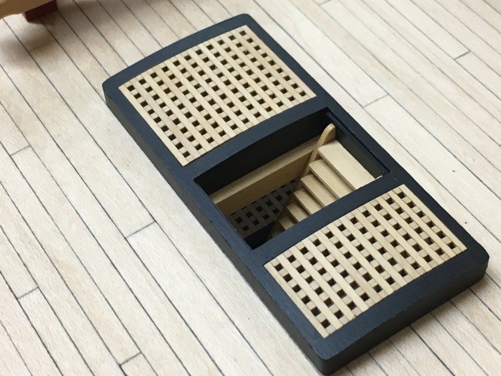
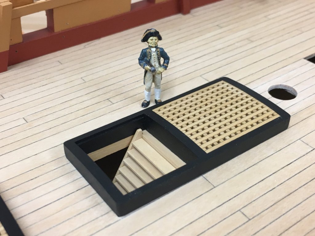
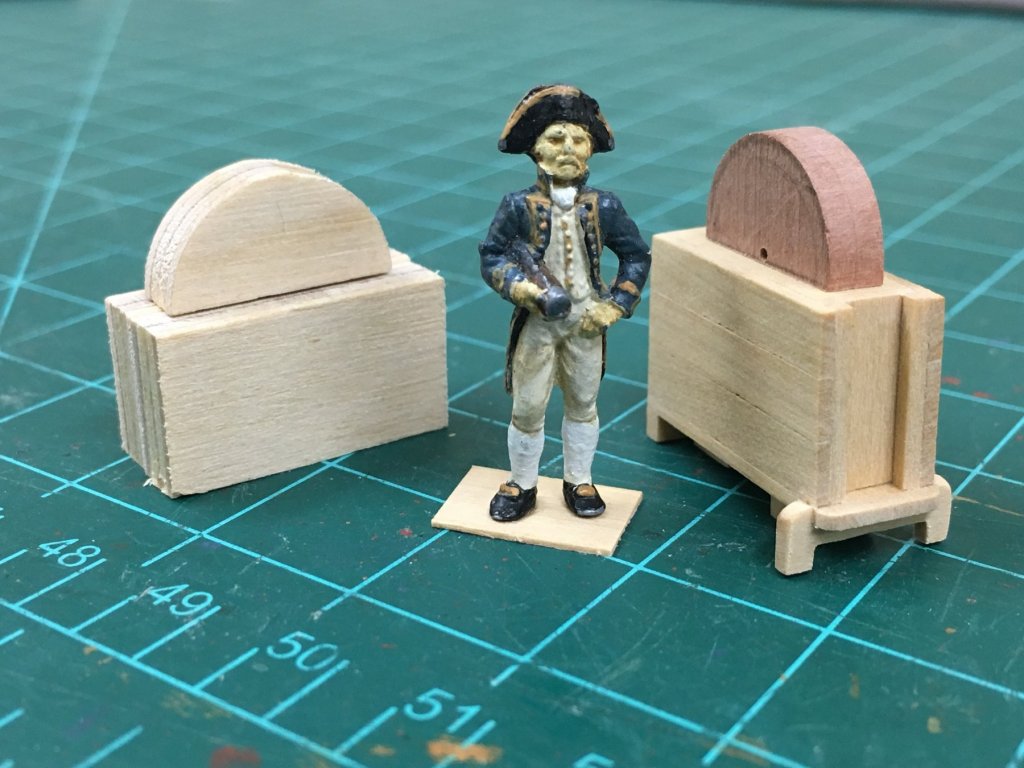
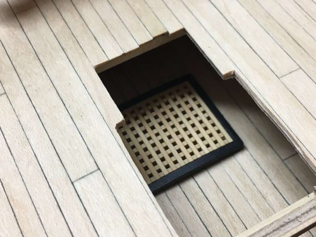
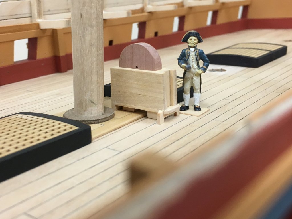
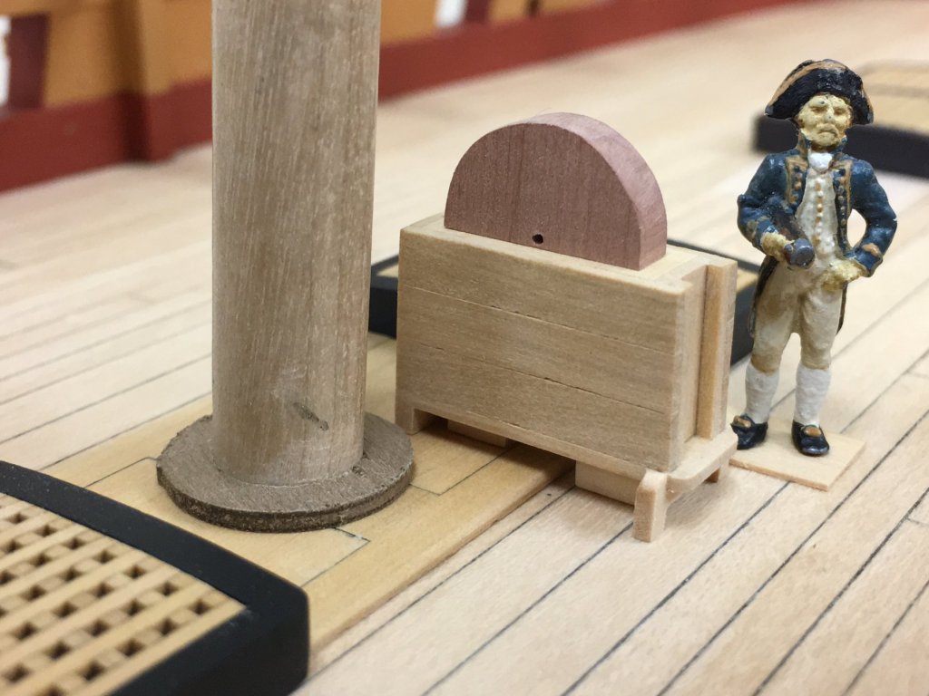
Thanks Mike, Al, Dirk, Thomas Pat, Joe and all the likes for kind words and continued interest. It feels like its been so long since I provided an update that I'm going to do just that, even though I don't think I've really reached a "point of completion" worthy of note, it will serve to document a few things before I forget. Ladders: How to approach these? Having known for some time I wouldn't be happy with the kit supplied items I've been pondering how to get a half decent result without the table saw that I aspire to one day! In the end, a simple jig made up some 2mm thick strip with one face carefully angled using a Proxxon disk sander proved to do the job well enough. Once the treads were cut to the same length, simply slotting into the jig, placing glue on the ends and placing the stringers proved simple enough. Removing from the jig after a couple if minutes before the glue cures fully makes for much easier (lower stress) removal. The central stringer on the wider ladder was simulated with individual 1x2mm pieces. The sharper eyed among you will notice a notch cut in the back of the wider one, more on that in a moment... Everything is just dry fitted, but pretty pleased with how these look in place. (Side-note: I did go a little crazy and placed a grating on the false lower deck as shown on the plans. This proved to actually be quite visible, more so in person than shows up in the photos and adds a little additional depth). For the main hatch, I ran into a little dilemma. In previous posts you can see how I had simulated the cross beam from the plans, this did cause a problem though when it came to figuring out how the ladder fits here. First attempt below was of a shorter stringer with one less tread, but although this terminates at the height of the beam, it just didn't seem right as it would be a real stretch for Captain Stirling to hoist his leg up reasonably. I also built a longer version with one additional riser, this seems more appropriate, but requires the aforementioned notch to be cut into the back of the stringer to fit around the beam. Despite hiding a feature I had quite proudly included, it does look better to my eye and certainly more practical - I can only speculate that this is the solution used on the real ship. Rejected first solution: Dockyard approved solution: Cole Pumps: Another very dominant feature that will be visible are the Cole chain pumps. The kit provides 3 pieces to build up into the cistern and the domed cover, but these would require painting. I wanted to try and improve on these, and possible explore keeping these a natural finish. After struggling to reconcile the dimensions in the AOTS book, I gave up because none of the scale diagrams agree to each other. In the end, I used the guidance in TFFM to approximate dimensions and adjusted to account for the wider width of the partners, and ensure that the height of the top of the cistern is a scale 3' 7" off the deck as TFFM specifies - this makes total sense as this would likely land mid chest for most people which would be an optimal height to operate most efficiently. The covers are still a work in progress as I will cover in castello planking. These are still in process, but overall, these took quite a while to figure out and proved to be very fiddly, but they are a heck of lot of fun to do! The mainmast partners have also been simulated using a simplified structure as this will be almost completely obscured when all the various pumps and cross pieces are finally in place. Paint choice for metal: Think I've decided on the colour to use for metal items, Tamiya Dark Iron XF-84. The photos of course don't show the subtlety visible to the eye, being a definite browny black, but this colour is very very similar to blackend brass. I've been reluctant to paint the beautiful RB barrels and the fact that this colour blends in so well means that I think I can now feel sure to keep these as is but know that non-metal items can be made to trick the eye. I built the stove provided in the kit up to prove this out and is a pleasant contrast to the Admiralty 'matte metal black ' used on the coamings and other wales. BTW - despite assembling this, I'm pretty sure I will be trying to scratch build my own stove....just because....

-
Swan class 3D model in progress
Beef Wellington replied to dvm27's topic in CAD and 3D Modelling/Drafting Plans with Software
Denis - just so you know, I find myself continually coming back to look at these pictures as they really show a level of detail just not normally seen on even the most perfectly executed models. So looking forward to being able to access somehow the complete library. Given the state of 3D printing, wouldn't it be nice if one could just hit 'print'....maybe one day- 141 replies
-
- 8
-
-
- pof swan series
- swan
- (and 1 more)